防护结构是抵抗侵彻破坏的工程防护结构,多层介质复合防护结构综合了不同材料的防护特性,改善了防护结构的能力,被广泛应用在军事、建筑等多种防护工程领域中[1]。对于多层介质复合防护结构来说,不同的结构层要发挥不同的性能特点。选取多层复合防护材料进行侵彻性能分析实验,通过数值分析的方式研究多层介质复合防护结构材料的侵彻性能[2]。
目前针对多层介质复合防护结构侵彻性能的数值分析方法有很多。如文献[3]提出了一种侵彻弹斜侵彻多层介质的三维数值仿真方法。利用有限元软件,对侵彻底层结构进行了全过程数值模拟;根据不同侵彻速度分析了侵彻深度、时间和过载等关键响应,得到了底层复合介质的侵彻规律以及对弹体结构的动态响应规律。文献[4]提出一种成层式防护结构抗超高速侵彻的数值分析方法。利用AUTODYN-2D和SPH算法开展了钨杆弹对4种“花岗岩遮弹层-(空气)干砂分配层-混凝土结构层”形式的成层式防护结构的超高速打击数值进行计算分析,得到了防护结构的破坏特征和能量分配情况。文献[5]提出陶瓷/液舱复合结构抗侵彻数值分析方法。在前期弹道冲击实验结果基础上,运用LS-DYNA进行了数值模拟,再现了陶瓷/液舱复合结构在弹体冲击下的破坏过程和破坏模式。
现有方法在一定程度上取得了实际工程进展,但是分析效果均未达到理想程度,数值分析准确率也偏低。为了能够更准确分析多层介质复合防护结构侵彻性能,本文提出了一种基于拓扑优化模型的多层介质复合防护结构侵彻性能的数值分析方法。利用均匀化方法以多层介质复合防护结构的刚度为目标,将材料用量作为约束条件,在此基础上进行微结构分析,推导出考虑惯性载荷的准则法公式,修正迭代算子中涉及惯性载荷灵敏度的计算值。
1 结构侵彻性能数值分析方法 1.1 基于均匀化方法的微结构分析在分析多层介质复合防护结构的力学行为时,由于多层介质复合材料具有高度异质性,因此设想具有周期性的无限小的微结构,利用微结构等效描述宏观结构物理特性的变化。微结构力学性能所遵循的方程为:
| $ \begin{array}{*{20}{c}} {{\mathit{\Phi }^\varepsilon }(X) = {\mathit{\Phi }^0}(X,Y) + \varepsilon {\mathit{\Phi }^1}(X,Y) + }\\ {{\varepsilon ^2}{\mathit{\Phi }^2}(X,Y) + \cdots + {\varepsilon ^n}{\mathit{\Phi }^n}(X,Y)} \end{array} $ | (1) |
式中:Φ是多层介质复合防护结构材料的密度;ε是一个极小的非负数(不为零),它用于表示微结构和整个防护结构体间的比值。
利用均匀化的方式分析多层介质复合材料中的微结构,得到多层介质复合防护结构的等效弹性模量:
| $ {D^H}(X) = \frac{1}{{\left| Y \right|}}\int_Y {\left( {\frac{{\partial X}}{{\partial Y}}} \right){\rm{d}}Y} $ | (2) |
式中:Y表示微结构体积;X表示微结构的微观特征位移场;H表示多层介质复合防护结构材料的等效弹性;∂表示多层介质复合防护结构材料的应力模量。
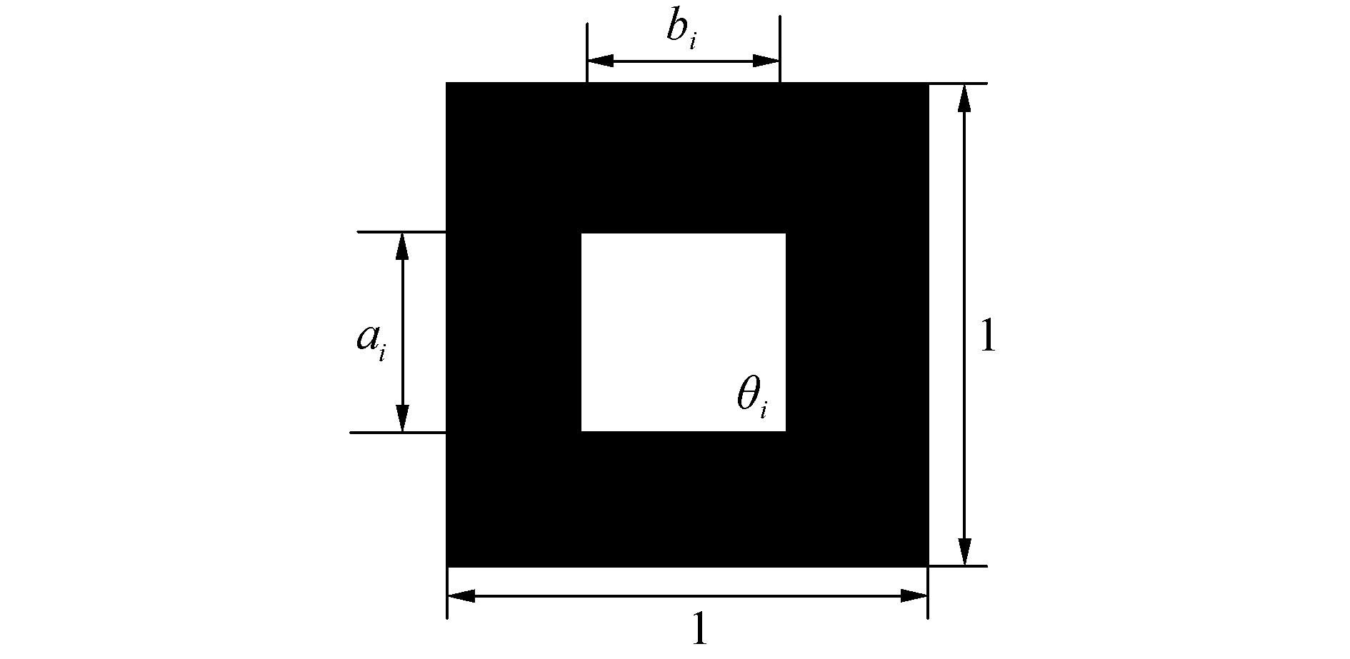
在进行多层介质复合防护结构拓扑优化时,利用均匀化思想。由于本文旨在对多层介质复合防护结构侵彻性能进行数值分析,因此考虑子弹冲击对多层介质复合防护结构的影响,采用有限元方法,将受冲击的多层介质复合防护结构离散为矩形带孔洞的单元结构,如图 1所示。
|
Download:
|
| 图 1 矩形孔洞单元结构 Fig. 1 Rectangular cavity element structure | |
图 1中,ai和bi表示矩形孔洞长度,θi表示孔洞转角,在此基础上求解等效的子弹冲击力、多层介质复合防护结构弹性模量、多层介质复合防护结构密度信息,创建结构刚度、质量矩阵和优化理论模型。
1.2 理论模型设计假设,Ω0是拓扑优化设计空间,Ω表示最优结果。对拓扑优化设计空间做离散处理,使其变成很小的单元。将去掉单元的假想密度设定成0,保留单元的假想密度设定成1。为了采用连续变量的优化方法求解,将单元的假想密度控制在0~1[6]。
假设Z是多层介质复合防护结构拓扑优化的设计变量,得到数学模型为:
| $ \left\{ {\begin{array}{*{20}{l}} {\min f\left( Z \right)}\\ {{\rm{s}}{\rm{.t}}{\rm{.}}\quad Z \le 0,J = 1,2, \cdots ,l} \end{array}} \right. $ | (3) |
式中:Z表示设计变量,它的取值集合为Z={z1, z2, …, zj, …,zn},zi={ai, bi, θi};f(Z)表示目标函数;l表示约束数量。
由于材料刚度是指材料或结构在受力时抵抗弹性变形的能力,因此本文将多层介质复合防护结构的刚度作为目标、将多层介质复合防护结构的体积当作约束条件[7],采用均匀化方法设计侵彻结构模型:
| $ \min C = \mathit{\boldsymbol{U}}\left( {{F_D} + {F_I}} \right) = {\mathit{\boldsymbol{U}}^2}\mathit{\boldsymbol{K}} = \sum\limits_{i = 1}^n {{u_i}{B_i}\mathit{\boldsymbol{D}}_i^H{B_i}{u_i}} $ | (4) |
| $ {\rm{s}}{\rm{.t}}{\rm{.}}\;\;\;\;\mathit{\boldsymbol{KU}} = {F_D} + {F_I} = {F_D} + \sum\limits_{i = 1}^n {{\rho _0}\left( {1 - {a_i}{b_i}} \right){\mathit{\Omega }_i}{\gamma _i}} $ | (5) |
| $ \sum\limits_{i = 1}^n {\left( {1 - {a_i}{b_i}} \right){\mathit{\Omega }_i}} \le {V_0} $ | (6) |
| $ {\gamma _i} = {\left( {{\gamma _{xi}},{\gamma _{yi}}} \right)^2} $ | (7) |
式中:U表示多层介质复合防护结构的受侵彻后的位移向量;K表示多层介质复合防护结构的整体刚度矩阵;FD表示恒载,其值不变;FI表示惯性载荷;ρ0表示微结构实体材料密度;V0表示多层介质复合防护结构的原始体积;DiH表示第i个单元的等效均匀化弹性矩阵;Ωi表示第i个单元面积;γi表示第i个单元的加速度向量。其中,0≤amin≤ai≤1,0≤bmin≤bi≤1。
构造微结构模型的拉格朗日方程为:
| $ \begin{array}{*{20}{c}} {L = C + \mathit{\Lambda }\left( {\sum_{i = 1}^n {\left( {1 - {a_i}{b_i}} \right){\mathit{\Omega }_i}} - {V_0}} \right) + }\\ {{\mathit{\boldsymbol{\lambda }}^{\rm{T}}}\left( {KU \cdot {F_D} - {F_I}} \right) + {\lambda _{a0}}\left( {{a_{\min }} - {a_i}} \right) + }\\ {{\lambda _{a1}}\left( {{a_i} - 1} \right) + {\lambda _{b0}}\left( {{b_{\min }} - {b_i}} \right) + {\lambda _{b1}}\left( {{b_i} - 1} \right)} \end{array} $ | (8) |
式中Λ和λ表示拉格朗日方程的乘子。在拓扑优化中[8],若Z的值低于下限时,取下限值;若Z的值高于上限时,取上限值[9]。
根据KKT条件可得:
| $ \begin{array}{*{20}{c}} {\frac{{\partial L}}{{\partial {a_i}}} = \frac{{\partial C}}{{\partial {a_i}}} + \left( { - {b_i}} \right){\mathit{\Omega }_i} + }\\ {\lambda \left[ {\frac{{\partial K}}{{\partial {a_i}}}U + K\frac{{\partial U}}{{\partial {a_i}}} - \frac{{\partial {F_I}}}{{\partial {a_i}}}} \right] = 0} \end{array} $ | (9) |
式中:
| $ \frac{{\partial C}}{{\partial {a_i}}} = \frac{{\partial {U^2}}}{{\partial {a_i}}}KU + U\frac{{\partial K}}{{\partial {a_i}}}U + {U^2}K\frac{\partial }{{\partial {a_i}}} $ | (10) |
将式(10)代入到式(9)可得:
| $ \begin{array}{*{20}{c}} {2{U^2}K\frac{{\partial U}}{{\partial {a_i}}} + {\lambda ^2}K\frac{{\partial U}}{{\partial {a_i}}} + \frac{{\partial K}}{{\partial {a_i}}}U + \lambda \frac{{\partial K}}{{\partial {a_i}}}U - }\\ {\lambda \frac{{\partial {F_I}}}{{\partial {a_i}}} + \mathit{\Lambda }\left( { - {b_i}} \right){\mathit{\Omega }_i} = 0} \end{array} $ | (11) |
设λ=-2U,此时式(11)可以简化成:
| $ - \mathit{\Lambda }\left( { - {b_i}} \right){\mathit{\Omega }_i} = - U\frac{{\partial K}}{{\partial {a_i}}}U + 2{U^2}\frac{{\partial {F_I}}}{{\partial {a_i}}} $ | (12) |
单元尺度下[10],式(12)将被改写为:
| $ - \mathit{\Lambda }\left( { - {b_i}} \right){\mathit{\Omega }_i} = - {u_i}\frac{{\partial {K_i}}}{{\partial {a_i}}}{u_i} + 2u_i^2\frac{{\partial {F_{Ii}}}}{{\partial {a_i}}} $ | (13) |
将式(13)的左右两侧同时除以-Λ(-bi)Ωi乘以ai,得到的迭代模型公式为:
| $ \begin{array}{*{20}{c}} {a_i^{k + 1} = E_{ai}^ka_i^k}\\ {E_{ai}^k = \frac{{ - {u_i}\left( {\partial {K_i}/\partial {a_i}} \right){u_i} + 2u_i^2\left( {\partial {F_{Ii}}/\partial {a_i}} \right)}}{{ - \mathit{\Lambda }\left( { - {b_i}} \right){\mathit{\Omega }_i}}}} \end{array} $ | (14) |
利用上述理论,构造的设计变量bi迭代模型为:
| $ \begin{array}{*{20}{c}} {b_i^{k + 1} = E_{bi}^kb_i^k}\\ {E_{bi}^k = \frac{{ - {u_i}\left( {\partial {K_i}/\partial {b_i}} \right){u_i} + 2u_i^2\left( {\partial {F_{Ii}}/\partial {b_i}} \right)}}{{ - \mathit{\Lambda }\left( { - {a_i}} \right){\mathit{\Omega }_i}}}} \end{array} $ | (15) |
常见的拓扑优化仅有恒载荷作用,而本文考虑到侵彻过程中惯性载荷的结构灵敏度,在上述得到的迭代模型(14)中增加了(2ui∂FIi/∂ai)项,式(15)增加了(2ui2∂FIi/∂bi)项[11]。这种结构灵敏度是非单调函数,迭代式很难形成最优解,这也成为了惯性力载荷工况存在时,拓扑优化问题求解的困难所在。为了解决结构灵敏度的非单调问题,修正了部分计算方式[12-13],则式(14)转变为:
| $ E_{ai}^k = \left( {\frac{V}{{{V_0}}}} \right)\frac{{2u_i^2\left( {\partial {F_{Ii}}/\partial {a_i}} \right)}}{{\mathit{\Lambda }{b_i}{\mathit{\Omega }_i}}} - \frac{{{u_i}\left( {\partial {K_i}/\partial {a_i}} \right){u_i}}}{{\mathit{\Lambda }{b_i}{\mathit{\Omega }_i}}} $ | (16) |
利用上述形式,对式(15)做相同处理。在拓扑优化阶段初期,如果目标函数值的变化很大,那么由侵彻惯性力所引起的振荡幅度就大[14-15],需要限制式(16)中的第1项值,减小第1项值的影响;如果目标函数值变化很小时,那么由侵彻惯性力项引起的振荡幅度就小,不需要限制式(16)中第1项的值。结合目标函数变化的情况,进一步修正模型(16):
| $ E_{ai}^k = {\left( {\frac{V}{{{V_0}}}} \right)^\mu }\frac{{2u_i^2\left( {\partial {F_{Ii}}/\partial {a_i}} \right)}}{{\mathit{\Lambda }{b_i}{\mathit{\Omega }_i}}} - \frac{{{u_i}\left( {\partial {K_i}/\partial {a_i}} \right){u_i}}}{{\mathit{\Lambda }{b_i}{\mathit{\Omega }_i}}} $ | (17) |
式中μ的取值方式为:
| $ \mu = \left\{ {\begin{array}{*{20}{l}} {1,\left| {{f_{k + 1}}\left( Z \right) - {f_k}\left( Z \right)} \right|/{f_k}\left( Z \right) > v}\\ {0,\left| {{f_{k + 1}}\left( Z \right) - {f_k}\left( Z \right)} \right|/{f_k}\left( Z \right) \le v} \end{array}} \right. $ | (18) |
式中:k表示迭代次数;v表示目标函数的相对变化量,v的取值范围在[0.01,0.1]。
2 实验结果与分析设计实验环境如下:实验平台内存:1TB,计算机操作系统:Windows10,实验软件:有限元分析软件。
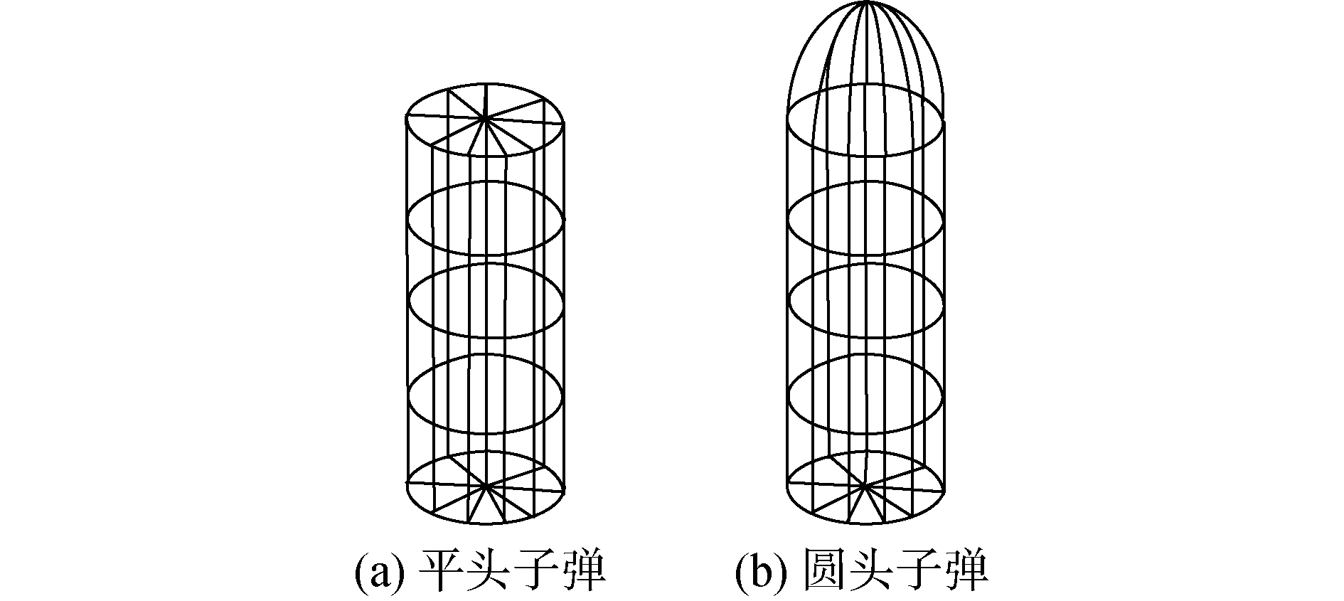
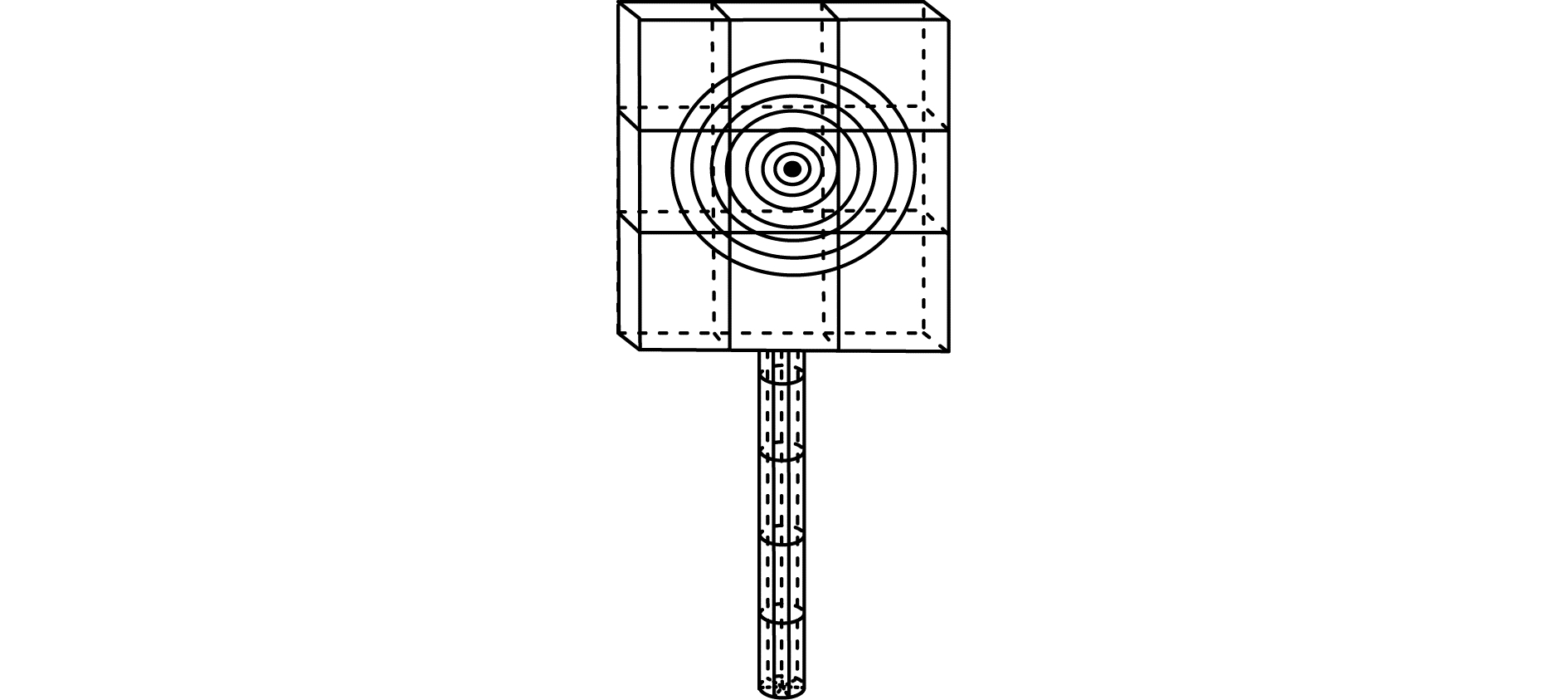
2.1 实验材料以子弹和多层介质复合防护结构的靶板作为实验材料,分析子弹对靶板防护结构的侵彻性能。设子弹和靶板模型分别为如图 2和图 3所示。
|
Download:
|
| 图 2 实验用2种几何形状的子弹模型 Fig. 2 Bullet models with two geometric shapes for experiments | |
|
Download:
|
| 图 3 多层介质复合防护结构靶板模型 Fig. 3 Target model of multi-layer dielectric composite protective structure | |
分别用图 2所示的2种形状的子弹对图 3所示的靶板进行射击。2种弹型侵彻多层介质复合防护结构靶板模型过程图如图 4所示。

|
Download:
|
| 图 4 2种弹型侵彻过程 Fig. 4 The penetration process of two types of projectiles | |
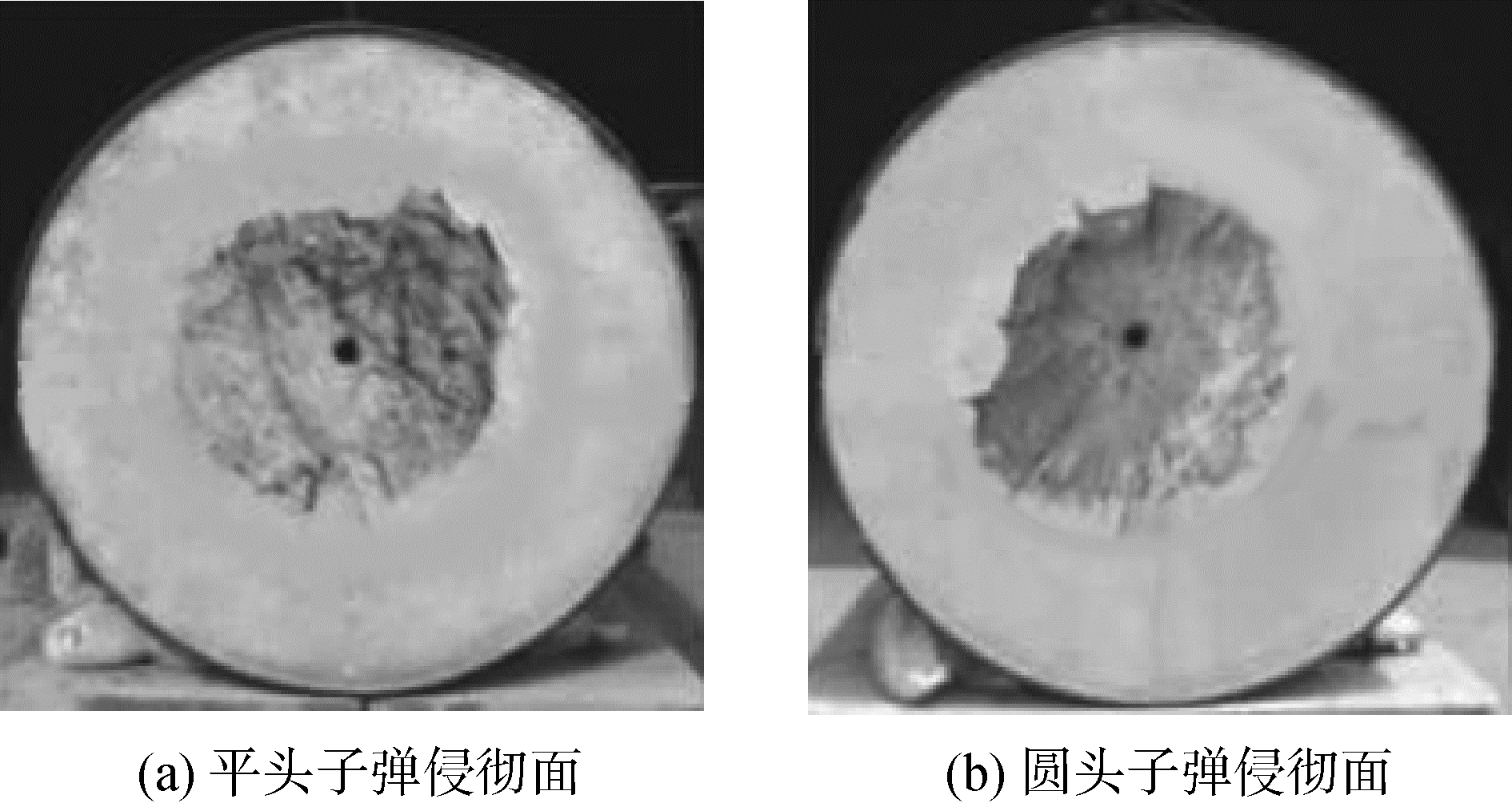
图 5分别为靶板受2种弹型的子弹侵彻后侵彻面的形状。
|
Download:
|
| 图 5 2种弹型子弹侵彻后侵彻面形状对比 Fig. 5 Comparison of penetration surface shapes of two kinds of projectile after penetration | |
根据不同子弹头部几何形状、着靶速度、子弹射靶角度等参数,创建7个子弹侵彻靶板的实验模型。全部模型关系和参数如表 1所示。
| 表 1 模型参数及其关系 Table 1 Model parameters and their relationships |
| 表 2 弹体侵彻靶板的深度 Table 2 Depth of projectile penetrating target |
使用侵蚀接触算法,计算时间是0.003 s,每2×10⁻⁵ s输出获取结果的数据文件。根据ls-dyna的处理程序读取计算出来的数值。
由模型1、2、3能够看出,着靶速度为60 m/s和50 m/s的子弹的击中靶板后剩余速度为零,子弹被留在了靶板内,着靶速度为60 m/s的子弹侵彻深度高于着靶速度为50 m/s的弹体侵彻深度,着靶速度为80 m/s的子弹贯穿了靶板,剩余速度是11.6 m/s。上述信息表明,随着子弹着靶速度的增加侵彻深度也随之增加。
由模型一、四、五和六能够看出,随着子弹射靶角度的变大,沿X轴方向的子弹侵彻深度逐渐减小。上述信息表明,垂直侵彻时结构的侵彻深度最大,在研发子弹时,仅能保证子弹垂直侵彻时的非致命特性。
由模型一和七能够看出,当2种弹头形状不同的子弹以同样的速度射击靶板时,平头子弹没有贯穿靶板,而圆头子弹均贯穿了靶板。2种子弹中平头子弹的侵彻耗能是相对更高的。
在60、70、80和90 m/s 4种着靶速度下,采用有限元模型对18.4 mm子弹的侵彻深度进行模拟分析,有限元模拟与历史经验数据计算结果对比如表 3所示。
| 表 3 有限元模拟与历史经验数据计算结果对比 Table 3 Comparisons between finite element simulation and historical empirical data |
由表 3能够看出,有限元模拟计算结果与历史经验数据的计算结果比较相近,2种结果间的差异均在20%以内。其中,着靶速度为60 m/s和70 m/s时,数值模拟的计算结果要低于历史经验数据,着靶速度为80 m/s和90 m/s时,历史经验数据的计算结果要高于数值模拟。表 3中数据可以充分说明本文所提的数值模拟方法是可行的。
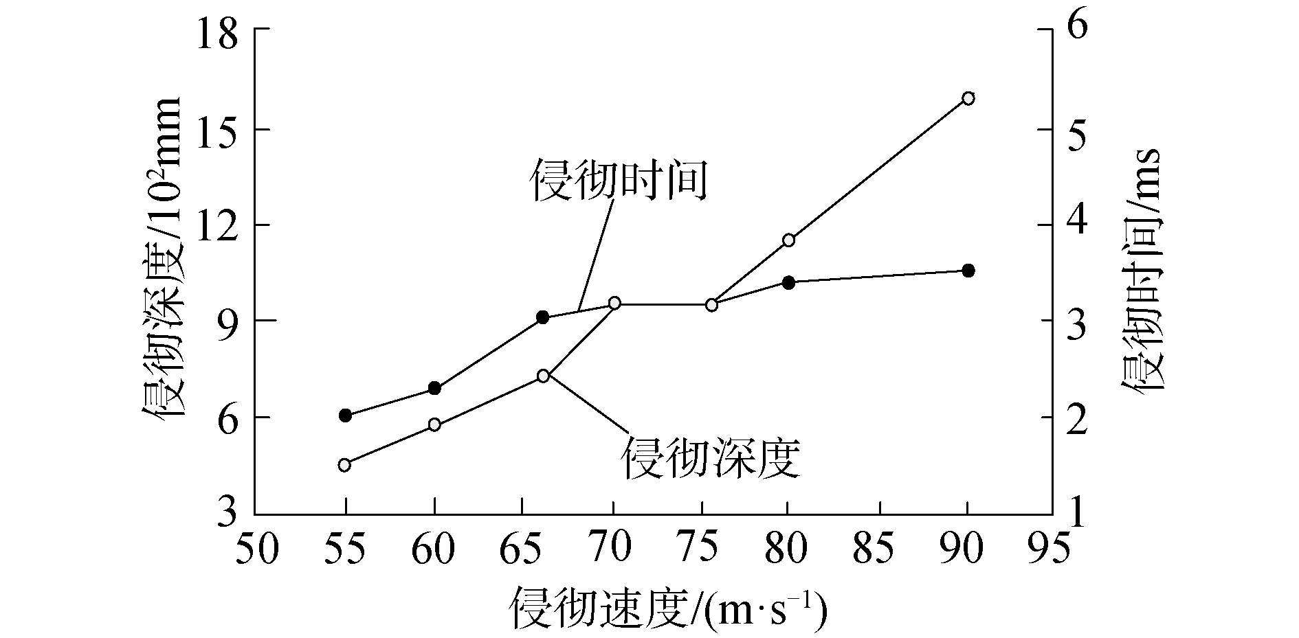
子弹着靶速度对侵彻的深度与时间的影响如图 6所示。
|
Download:
|
| 图 6 侵彻深度和时间与侵彻速度间的变化关系 Fig. 6 The relationship between penetration depth and time and penetration velocity | |
由图 6能够看出,整体来说子弹侵彻多层介质复合防护结构靶板的深度受到侵彻速度增加的影响而加深。当子弹的侵彻速度在[70, 75]m/s时,子弹侵彻靶板的深度不会受到侵彻速度增加的影响而增加;当子弹的侵彻速度在[75, 90]m/s时,侵彻深度会受到侵彻速度增加的影响而增加。
子弹侵彻靶板所用时间随侵彻速度的加快而增加,当子弹的侵彻速度在[55, 90]时,侵彻靶板所需时间的增长值非常小,仅为1.5 ms。
综上所述,完成了对多层介质复合防护结构侵彻性能的数值分析,所提数值分析方法的分析结果准确性非常高,能够满足用户的需求。
3 结论1) 增加子弹着靶速度可以增大对靶板的侵彻深度。
2) 着靶速度相同时,子弹入射角度的增大不会影响子弹的总体侵彻深度,沿X轴方向靶板的侵彻深度降低。
3) 采用不同弹头的子弹在射击靶板时,平头子弹受到靶板的阻力要明显高于圆头与尖头子弹。子弹贯穿靶板时,平头子弹的能耗最高,尖头子弹能耗最低。
4) 由于有限元模拟和历史经验数据的计算结果差异性低于20%,所以创建的有限元模型实用性较强。
| [1] |
张雁思, 徐豫新, 任杰, 等. 陶瓷/玻纤复合防护结构层间位置对抗破片侵彻性能的影响规律研究[J]. 弹箭与制导学报, 2016, 36(6): 61-66. ZHANG Yansi, XU Yuxin, REN Jie, et al. Research on the influence of ceramic/glass fiber composite protective structure interlayer position on anti-penetration performance[J]. Journal of projectiles, rockets, missiles and guidance, 2016, 36(6): 61-66. (  0) 0)
|
| [2] |
苟瑞君, 孙丹, 张博. 陶瓷/泡沫铝/铝合金复合装甲抗射流侵彻性能[J]. 含能材料, 2017, 25(6): 451-458. GOU Ruijun, SUN Dan, ZHANG Bo. Anti-jet penetration performances of the ceramic/aluminum foam/aluminum alloy composite armor[J]. Chinese journal of energetic materials, 2017, 25(6): 451-458. (  0) 0)
|
| [3] |
曾必强, 姜春兰, 李明, 等. 侵彻弹斜侵彻多层介质的三维数值仿真[J]. 弹道学报, 2008, 20(2): 9-12, 16. ZENG Biqiang, JIANG Chunlan, LI Ming, et al. 3D numerical simulation of oblique penetration of projectile into multilayer medium target[J]. Journal of ballistics, 2008, 20(2): 9-12, 16. (  0) 0)
|
| [4] |
刘峥, 程怡豪, 邱艳宇, 等. 成层式防护结构抗超高速侵彻的数值分析[J]. 爆炸与冲击, 2018, 38(6): 1317-1324. LIU Zheng, CHENG Yihao, QIU Yanyu, et al. Numerical analysis on hypervelocity penetration into layered protective structure[J]. Explosion and shock waves, 2018, 38(6): 1317-1324. (  0) 0)
|
| [5] |
仲强, 侯海量, 李典. 陶瓷/液舱复合结构抗侵彻机理试验研究[J]. 船舶力学, 2017, 21(10): 1282-1290. ZHONG Qiang, HOU Hailiang, LI Dian. Experimental study on anti-penetration mechanism of ceramic/fluid cabin composite structure[J]. Journal of ship mechanics, 2017, 21(10): 1282-1290. DOI:10.3969/j.issn.1007-7294.2017.10.012 (  0) 0)
|
| [6] |
李国举, 范群波, 王扬卫, 等. SiC/Al双连通复合装甲材料抗侵彻性能宏-微观跨尺度模拟[J]. 无机材料学报, 2017, 32(4): 425-430. LI Guoju, FAN Qunbo, WANG Yangwei, et al. Multi-scale simulation of interpenetrating SiC/Al composite armor materials subjected to impact loading using a macro-micro approach[J]. Journal of inorganic materials, 2017, 32(4): 425-430. (  0) 0)
|
| [7] |
郭锐, 周昊, 刘荣忠, 等. 陶瓷棒填充点阵金属夹层结构的制备及抗侵彻实验[J]. 复合材料学报, 2016, 33(4): 921-928. GUO Rui, ZHOU Hao, LIU Rongzhong, et al. Preparation and anti-penetration experiment of metal lattice truss cored sandwich structures filled with ceramic rods[J]. Acta materiae compositae sinica, 2016, 33(4): 921-928. (  0) 0)
|
| [8] |
吴晓光, 李典, 吴国民, 等. 高速杆式弹侵彻下蓄液结构的防护能力[J]. 爆炸与冲击, 2018, 38(1): 76-84. WU Xiaoguang, LI Dian, WU Guomin, et al. Protection ability of liquid-filled structure subjected to penetration by high-velocity long-rod projectile[J]. Explosion and shock waves, 2018, 38(1): 76-84. (  0) 0)
|
| [9] |
翁浦莹, 康凌峰, 孔春凤, 等. 组合式三维机织复合材料的制备及其抗高速冲击性能[J]. 纺织学报, 2016, 37(3): 60-65. WENG Puying, KANG Lingfeng, KONG Chunfeng, et al. Preparation and high velocity impact performance of combined 3-D woven composites[J]. Journal of textile research, 2016, 37(3): 60-65. (  0) 0)
|
| [10] |
郭锐, 南博华, 周昊, 等. 点阵金属夹层结构抗侵彻实验研究[J]. 振动与冲击, 2016, 35(24): 45-50. GUO Rui, NAN Bohua, ZHOU Hao, et al. Experiment assessment of the ballistic response of a hybrid-cored sandwich structure[J]. Journal of vibration and shock, 2016, 35(24): 45-50. (  0) 0)
|
| [11] |
乔金超, 吴越, 贾磊朋, 等. 双层复合线型药型罩侵彻靶板的数值分析[J]. 兵工自动化, 2017, 36(9): 27-30. QIAO Jinchao, WU Yue, JIA Leipeng, et al. Numerical analysis of double-layer composite linear liner penetrate target[J]. Ordnance industry automation, 2017, 36(9): 27-30. (  0) 0)
|
| [12] |
焦志刚, 杜宁, 寇东伟. 双模聚能战斗部成型装药的结构优化[J]. 计算机仿真, 2017, 34(2): 1-4. JIAO Zhigang, DU Ning, KOU Dongwei. Optimization of shaped charge for the dual-mode warhead[J]. Computer simulation, 2017, 34(2): 1-4. DOI:10.3969/j.issn.1006-9348.2017.02.001 (  0) 0)
|
| [13] |
邓云飞, 袁家俊, 徐建新. 半球形头弹不同角度冲击下编织复合材料板的侵彻特性[J]. 复合材料学报, 2018, 35(4): 843-849. DENG Yunfei, YUAN Jiajun, XU Jianxin. Penetration characteristics of woven composite laminates impacted by hemispherical-nosed projectiles at different angles[J]. Acta materiae compositae sinica, 2018, 35(4): 843-849. (  0) 0)
|
| [14] |
VINCENT M, XOLIN P, GEVREY A M, et al. Experimental and numerical analysis of penetration/removal response of endodontic instrument made of single crystal Cu-based SMA:comparison with NiTi SMA instruments[J]. Smart materials and structures, 2017, 26(4): 045014. DOI:10.1088/1361-665X/aa5f0b (  0) 0)
|
| [15] |
蒙朝美, 蒋志刚, 蔡良才, 等. 正六边形钢管约束混凝土靶抗侵彻性能的数值模拟[J]. 弹道学报, 2017, 29(4): 64-69. MENG Chaomei, JIANG Zhigang, CAI Liangcai, et al. Numerical simulation of anti-penetration performance for hexagonal steel-tube-confined concrete target[J]. Journal of ballistics, 2017, 29(4): 64-69. DOI:10.3969/j.issn.1004-499X.2017.04.011 (  0) 0)
|
 2019, Vol. 40


