波浪爬升是海洋工程中的热点问题[1]。线性的势流方法只能计算线性波浪的作用[2]。对于弱非线性入射波,二阶理论会提高预报精度[3-4]。但仍受限于理论假设,无法准确预报强非线性入射波作用下的波浪爬升问题以及粘性效应[5]。计算流体动力学(computational fluid dynamics,CFD)方法通过直接求解纳维-斯托克斯(Navier-Stokes,N-S)方程,没有理论假设,可以预报强非线性波浪爬升问题[6]。但相比于势流方法,粘流方法的计算成本更高[7]。采用势粘流单向耦合技术可以减小数值模拟计算域,降低计算成本[8-11]。
本文参考文献[12-13]的模型试验数据,采用势粘流单向耦合技术对单直立固定圆柱的波浪爬升进行了全尺度数值模拟。
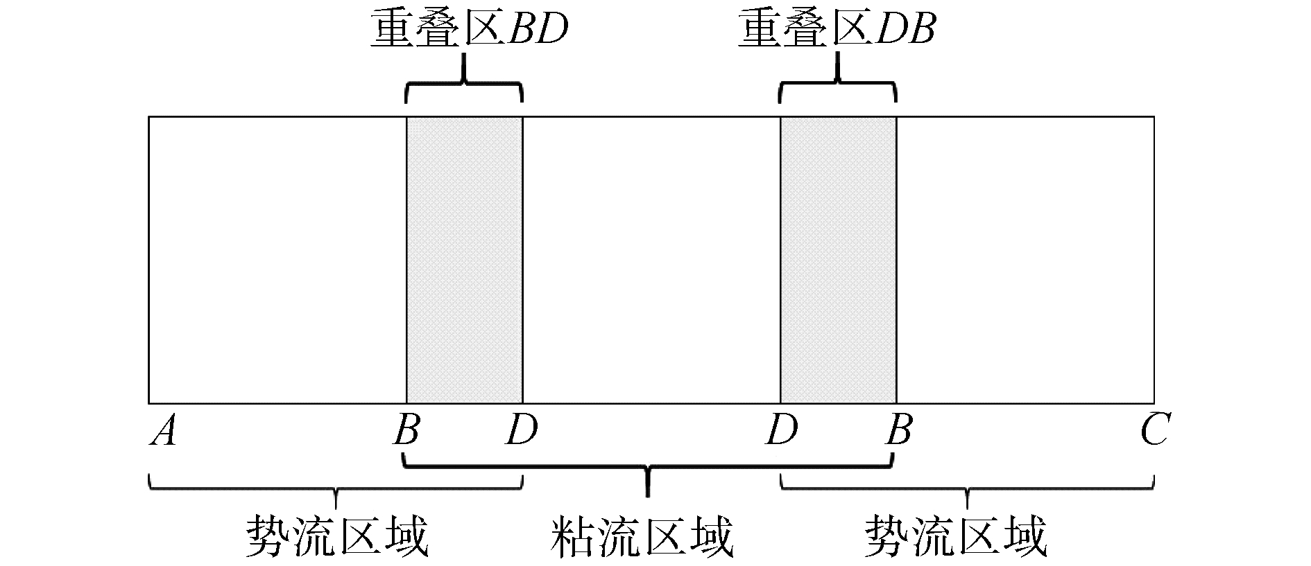
1 势粘流单向耦合技术控制方程在实际物理流动过程中,粘性只在物体近壁面边界层起主导作用,所以在远离物体的流场中可以采用势流求解以提高计算效率。本文采用的势粘流单向耦合技术,基于STAR-CCM+求解器,把计算域分为粘流区域与势流区域,在粘流区求解不可压缩N-S方程,在势流区求解欧拉方程。在势粘流重叠区进行势粘流求解匹配,见图 1。
|
Download:
|
| 图 1 势粘流耦合区域分布 Fig. 1 The distribution of potential viscous flow coupling region | |
本文在粘流区域采用有限体积法对控制方程进行离散,采用流体体积函数(VOF)方法捕捉气体与水之间的交界面。湍流模型选择分离涡(DES)模型[14]:
| $ \begin{array}{l}{\int\limits_{V} \frac{\partial}{\partial t}(\rho \overline{ \mathit{\boldsymbol{v}}}) \mathrm{d} V+\int\limits_A \rho \overline{ \mathit{\boldsymbol{v v}}} \mathrm{d} \mathit{\boldsymbol{a}}=} \\ {-\int\limits_{V} \nabla \overline{ \mathit{\boldsymbol{p}}} \mathrm{d} V+\int\limits_{V} \nabla \cdot\left(\tau+\tau_{t}^{\mathrm{RANS}}\right) \mathrm{d} V+\int\limits_{V} S_{\phi} \mathrm{d} V}\end{array} $ | (1) |
| $ \begin{array}{l}{\int\limits_V \frac{\partial}{\partial t}(\rho \tilde{ \mathit{\boldsymbol{v}}}) \mathrm{d} V+\int\limits_A \rho \tilde{\mathit{\boldsymbol{v}}} \tilde{ \mathit{\boldsymbol{v}}} \mathrm{d} \mathit{\boldsymbol{a}}=} \\ {\quad-\int\limits_{V} \nabla \tilde{ \mathit{\boldsymbol{p}}} \mathrm{d} V+\int\limits_{V} \nabla \cdot\left(\tau+\tau_{t}^{\mathrm{LES}}\right) \mathrm{d} V+\int\limits_{V} S_{\phi} \mathrm{d} V}\end{array} $ | (2) |
式(1)、(2)分别表示分别在RANS与LES下的控制体体积为V,在表面积为A的N-S方程; a表示流体表面A的矢量。v是流体运动速度,p是压力; τ表示粘性应力张量;Sϕ表示源项。τtRANS代表RANS下的雷诺应力,根据湍流模型τtRANS=f(▽· v, k, ε)来确定;k是湍动能;ε是湍流耗散率。τtLES代表LES下的亚格子应力,与亚格子模型τtLES=
DES结合了雷诺平均(RANS)与大涡模拟(LES)。在RANS中
在势流区不考虑粘性的作用,可将N-S方程简化为欧拉方程:
| $ \frac{\partial \boldsymbol{v}}{\partial t}+(\boldsymbol{v} \cdot \nabla) \boldsymbol{v}=-\frac{1}{\rho} \nabla p-g \boldsymbol{k} $ |
对势流区域流体作无旋假设之后,势流区域基于层析水波理论的二维有限水深IGN模型给出规则波。二维有限水深IGN模型的基本方程如下[15]。
假设海底条件z=-h(x),自由面z=ζ(x), 自由面上压力为零,即
| $ u(x, z, t)=\frac{\partial \psi(x, z, t)}{\partial z} $ | (3) |
| $ w(x, z, t)=-\frac{\partial \psi(x, z, t)}{\partial x} $ | (4) |
令ψ(x, z, t)在海底的值为零,ψ(x, α, t)=0。对IGN模型的速度场作近似求解:
| $ \psi(x, z, t)=\sum\limits_{m=1}^{K} \psi_{m}(x, t) f_{m}(\gamma)=\sum\limits_{m=1}^{K} \psi_{m}(x, t) \gamma^{2 m-1} $ |
其中γ=(z+h)/(ζ+h)。
关于瞬时波面ζ(x, t)和自由水面上的速度势
| $ \zeta_{t}+\hat{\psi}_{x}=0 $ | (5) |
| $ \hat{\varphi}_{t}=-\frac{\partial}{\partial x} \frac{\partial T}{\partial \zeta_{x}}+\frac{\partial T}{\partial \zeta}-g \zeta $ | (6) |
式中:
| $ T=\frac{1}{2} \sum\limits_{m=1}^{K} \sum\limits_{n=1}^{K}\left\{(\zeta+h) A_{\mathrm{mn}} \psi_{m x} \psi_{n x}-2\left[(\zeta+h)_{x} B_{\mathrm{mn}}^{1}-\right.\right.\\ \qquad h_{x} B_{\mathrm{mn}} ] \psi_{m x} \psi_{n}+\frac{1}{\theta}\left[\left(1+h_{x}^{2}\right) C_{\mathrm{mn}}-2\left(\zeta h_{x} C_{\mathrm{mn}}^{1}+\right.\right.\\ \qquad \left(\zeta+h_{x}\right)^{2} C_{\mathrm{mn}}^{2} ] \psi_{m} \psi_{n} \} $ | (7) |
其中:θ=ζ+h,Amn=∫01fm(γ)fn(γ)dγ,Bmn1= ∫01γfm(γ)f′n(γ)dγ,Bmn=∫01fm(γ)f′n(γ)dγ,Cmn= ∫01f′m(γ)f′n(γ)dγ,Cmn1=∫01γf′m(γ)f′n(γ)dγ,Cmn2= ∫01γ2f′m(γ)f′n(γ)dγ。
为了使方程闭合,给出自由水面速度势
| $ f_{m}(1) \hat{\varphi}_{x}=-\frac{\partial}{\partial x} \frac{\partial T}{\partial \psi_{m, x}}+\frac{\partial T}{\partial \psi_{m}} $ |
在势粘流重叠区需要对势流和粘流进行耦合匹配,通过式(8)标量ϕ的输运方程来说明这一过程:
| $ \int\limits_{V} \frac{\partial}{\partial t}(\rho \phi) \mathrm{d} V+\int\limits_{A} \rho \phi \mathit{\boldsymbol{v}} \mathrm{d} \mathit{\boldsymbol{a}}=\int\limits_{A} \varGamma \nabla \phi \cdot \mathrm{d} \mathit{\boldsymbol{a}}+\int\limits_{V} S_{\phi} \mathrm{d} V $ | (8) |
其中:
| $ S_{\phi}^{*}=S_{\phi}-\mu(x) \rho\left(\phi-\phi_{w}\right) $ | (9) |
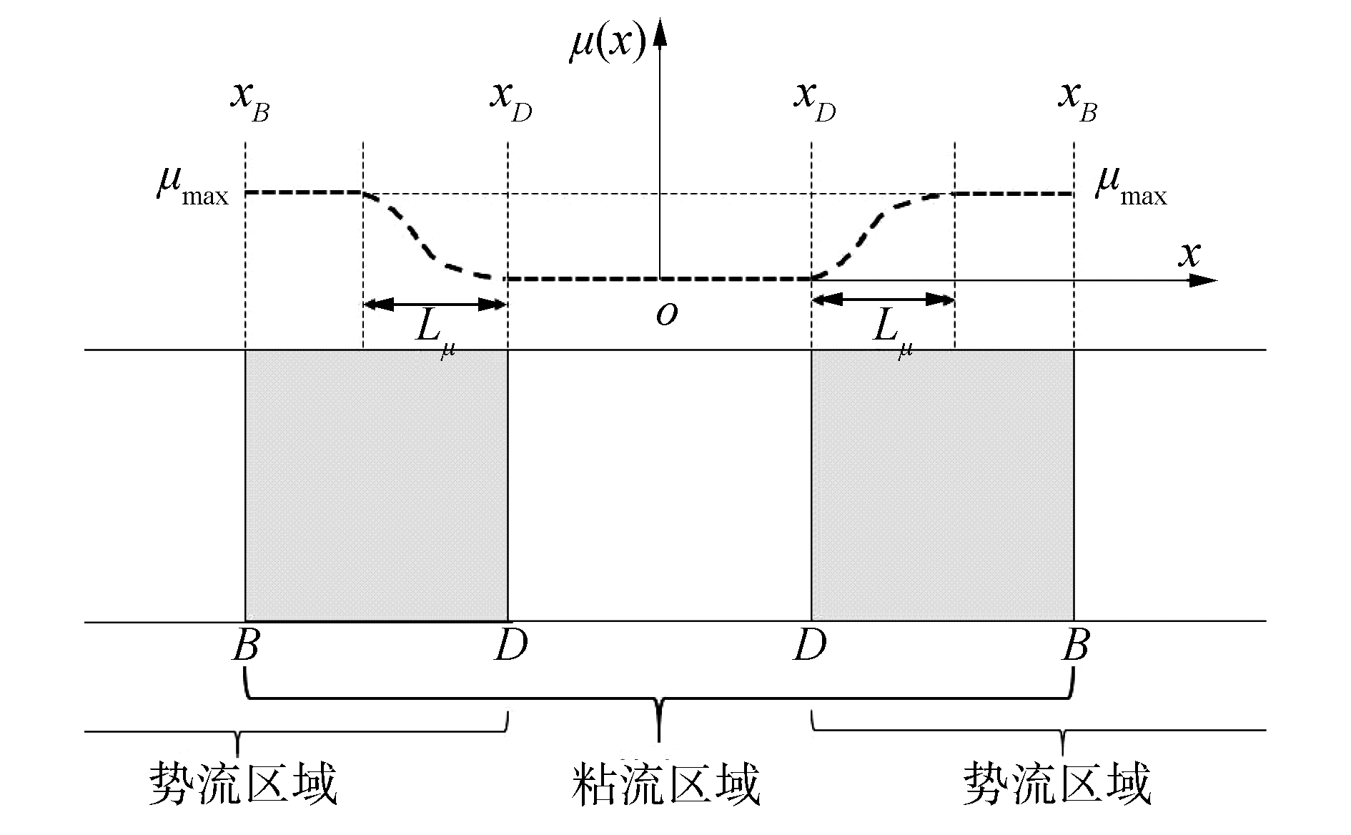
式中:Γ代表流体粘性系数;Sϕ表示源项。当物理量ϕ是流场中的速度分量时,式(8)代表动量守恒方程;当ϕ是体积分数时,式(8)代表体积项守恒方程。在重叠区中,需要对式(8)右侧的源项进行修正,消除CFD区域内的反射。式(9)是修正后的源项Sϕ*,其中ϕw是已知量,可以根据IGN得到。μ(x)表示衰减函数,μ(x)随空间x位置变化可见图 2。以DB重叠区为例,重叠区边界D上μ(x)=0,而在DB其他区域则会随着重叠区域的不同位置而变化。式(10)给出了μ(x)在DB上的计算公式。
|
Download:
|
| 图 2 重叠区DB(BD)衰减函数μ(x)示意 Fig. 2 Schematic sketch for damping function of overlapping area DB(BD) | |
| $ \mu(x)=\left\{\begin{array}{ll}{0, } & {x<x_{D}} \\ {\mu_{\max }\left(\sin ^{2} \frac{{\rm{ \mathsf{ π} }}\left(x-x_{D}\right)}{2 L_{\mu}^{2}}\right), } & {x_{D} \leqslant x \leqslant L_{\mu}} \\ {\mu_{\max }, } & {L_{\mu}<x \leqslant x_{B}}\end{array}\right. $ | (10) |
式中:μmax表示最大衰减系数,根据波周期T得到μmax=π/T。本文中过渡区DB的长度为2D,D代表圆柱直径。
2 数值计算 2.1 试验设置本文对模型试验做1:50.3的全尺度模拟,试验浪高仪设置见图 3。圆柱半径r=8 m,吃水24 m,坐标原点在水线处的圆心。在圆柱周围每隔45°布置浪高仪。包括圆柱内侧浪高仪WPB1~WPB5和外侧WPO1~WPO5。

|
Download:
|
| 图 3 浪高仪位置 Fig. 3 Location of the wave probes | |
图 3中黑实线代表圆柱,外侧虚线圆代表外侧浪高仪位置所在圆。内侧浪高仪与圆柱表面距离为0.206 3 m,外侧浪高仪与圆柱表面的距离等于圆柱半径。本文研究来波为规则波,波浪条件见表 1。
| 表 1 波浪条件 Table 1 Wave conditions |
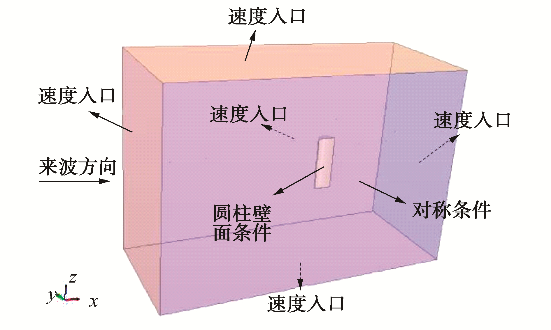
数值模拟的计算域长度为2(L+2D);为减小计算量,采用对称的思想只对一半圆柱进行数值模拟,计算域宽度大小为8D;计算域深度设为L。计算域边界条件设置见图 4,对称位置采用对称条件,计算域其他边界都采用速度入口的边界条件,圆柱表面选择壁面条件。
|
Download:
|
| 图 4 边界条件 Fig. 4 Boundary conditions | |
根据STAR-CCM+造波经验,在自由液面处水平方向网格大小设为L/80,垂直方向为H/20。对圆柱壁面进行网格加密,见图 5。

|
Download:
|
| 图 5 圆柱壁面网格加密 Fig. 5 Mesh refinement around the column wall surface | |
圆柱壁面的加密网格在水平以及垂直方向大小相等。圆柱壁面附近不同网格大小参数以及计算域网格总数见表 2。
| 表 2 圆柱壁面网格参数 Table 2 Mesh parameters on the column wall surface |
根据圆柱水平方向力Fx以及垂直方向受力Fz对圆柱壁面网格参数做收敛性分析,见图 6。

|
Download:
|
| 图 6 圆柱壁面网格收敛性分析 Fig. 6 Mesh convergence analysis of cylinder surface | |
由图 6可知,圆柱水平力Fx在网格1时收敛,垂向力Fz在网格2时收敛。即为了预报圆柱垂向受力,圆柱壁面在垂直方向的网格大小应与自由液面处保持一致。
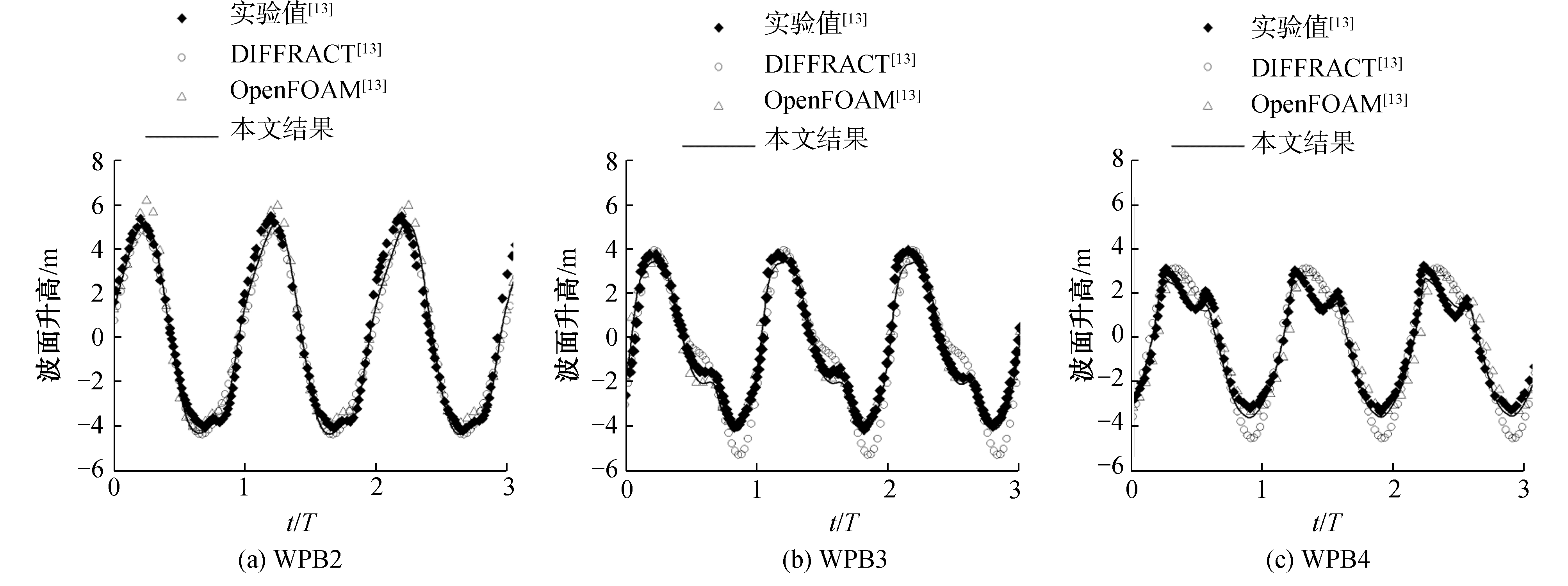
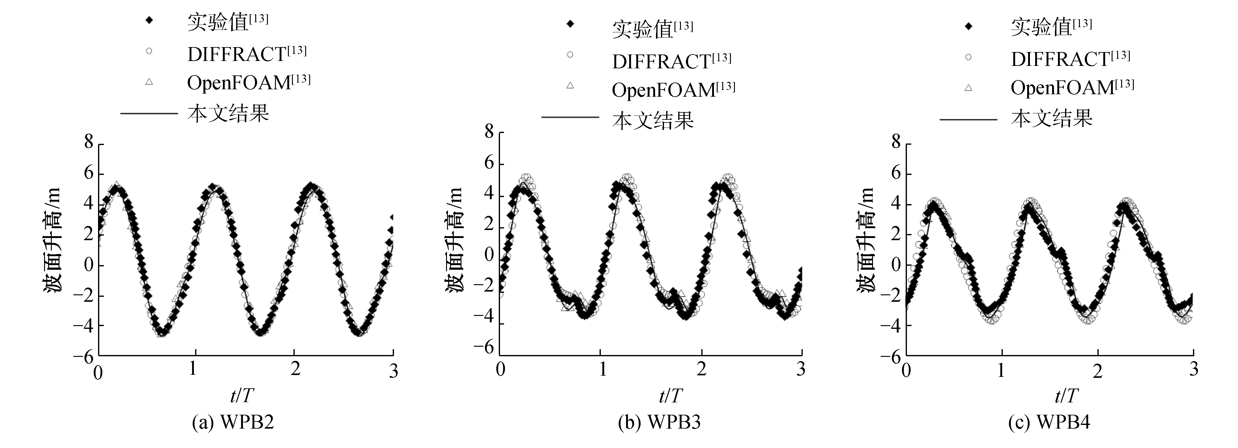
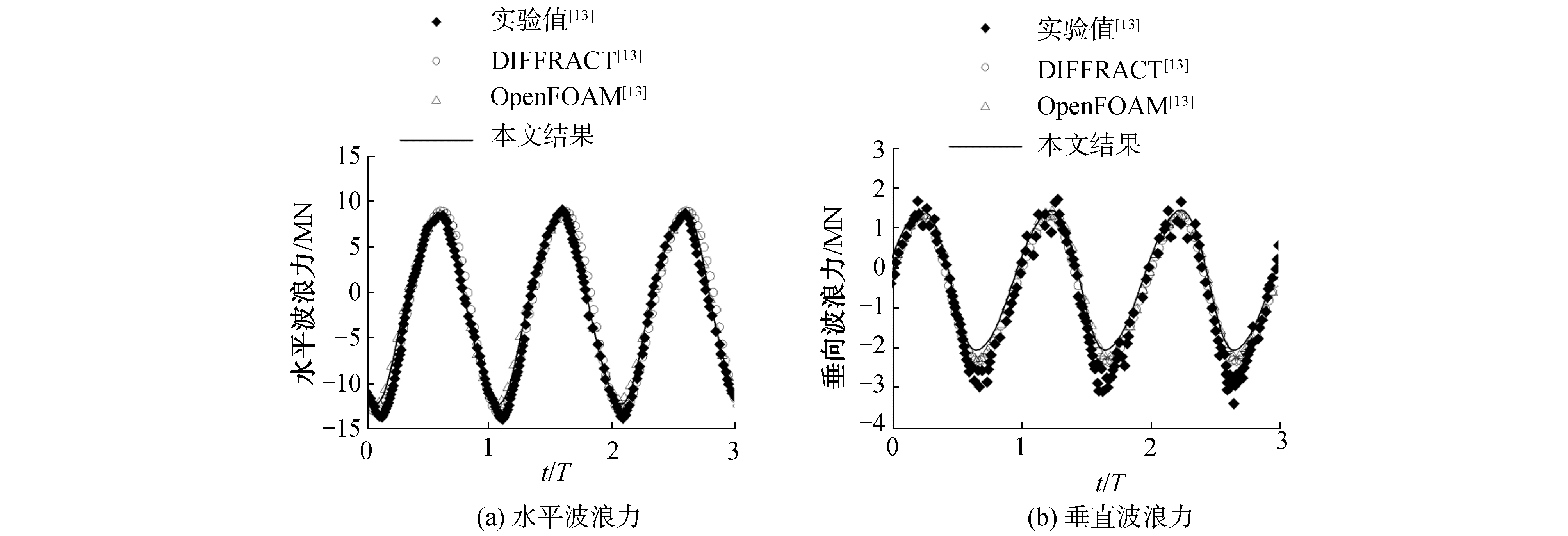
3 结果讨论 3.1 波面及波浪力时历曲线验证以T=9 s,波陡H/L=1/16为例,波面以及圆柱水平、垂向波浪力的数值模拟时历曲线结果与文献中的试验值EXP、势流DIFFRACT以及粘流OpenFOAM数值结果进行对比验证。圆柱内侧浪高仪WPB2~WPB4的时历结果见图 7,外侧浪高仪WPO2~WPO4的波面时历曲线见图 8,圆柱波浪力时历曲线验证见图 9。
|
Download:
|
| 图 7 圆柱内侧波面时历对比 Fig. 7 Wave elevation comparison at the inner side of the column | |
|
Download:
|
| 图 8 圆柱外侧波面时历对比 Fig. 8 Wave elevation comparison at the outer side of the column | |
|
Download:
|
| 图 9 圆柱波浪力时历对比 Fig. 9 Wave forces comparison acting on the cylinder | |
由图可知势流DIFFRACT求解器可以准确预报波面爬升幅值,但对于高阶项的捕捉误差较大;采用粘流OpenFOAM求解器可以准确预报波面爬升的非线性效应, 文献[13]中使用了8.29×10⁶网格。采用势粘流单向耦合技术,网格数为1.14×10⁶,并且对WPB2~WPB4和WPO2~WPO4处的波面以及圆柱波浪力数值预报结果与试验值吻合良好。
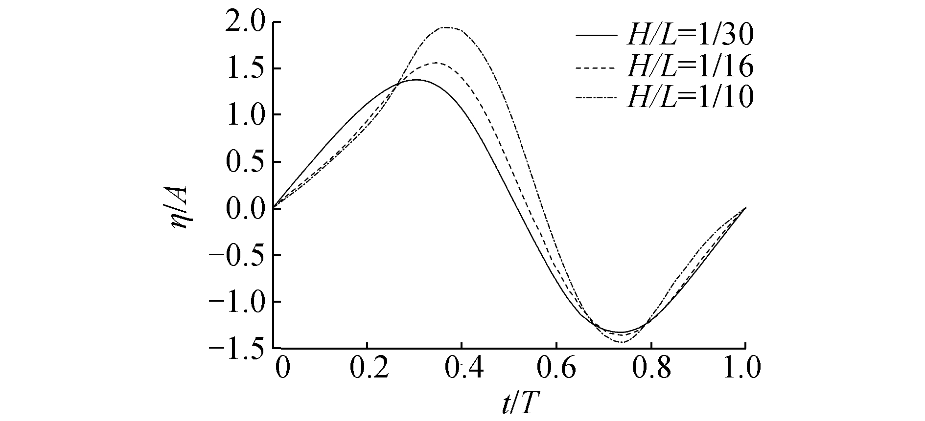
3.2 波浪绕射谐波分析以T=9 s为例比较不同非线性下波浪爬升的绕射效应。迎浪位置WPB1处波浪爬升的高度最大[16]。比较不同波陡下WPB1位置处在一个周期内的波面时历, 见图 10。
|
Download:
|
| 图 10 不同波陡时WPB1波面信号(T=9 s) Fig. 10 Wave elevation at WPB1 with different wave steepness(T=9 s) | |
由图 10可知,入射波非线性越强,波浪爬升高度越大。在波陡H/L=1/10时,WPB1处的最大爬升高度可达2.0 A。
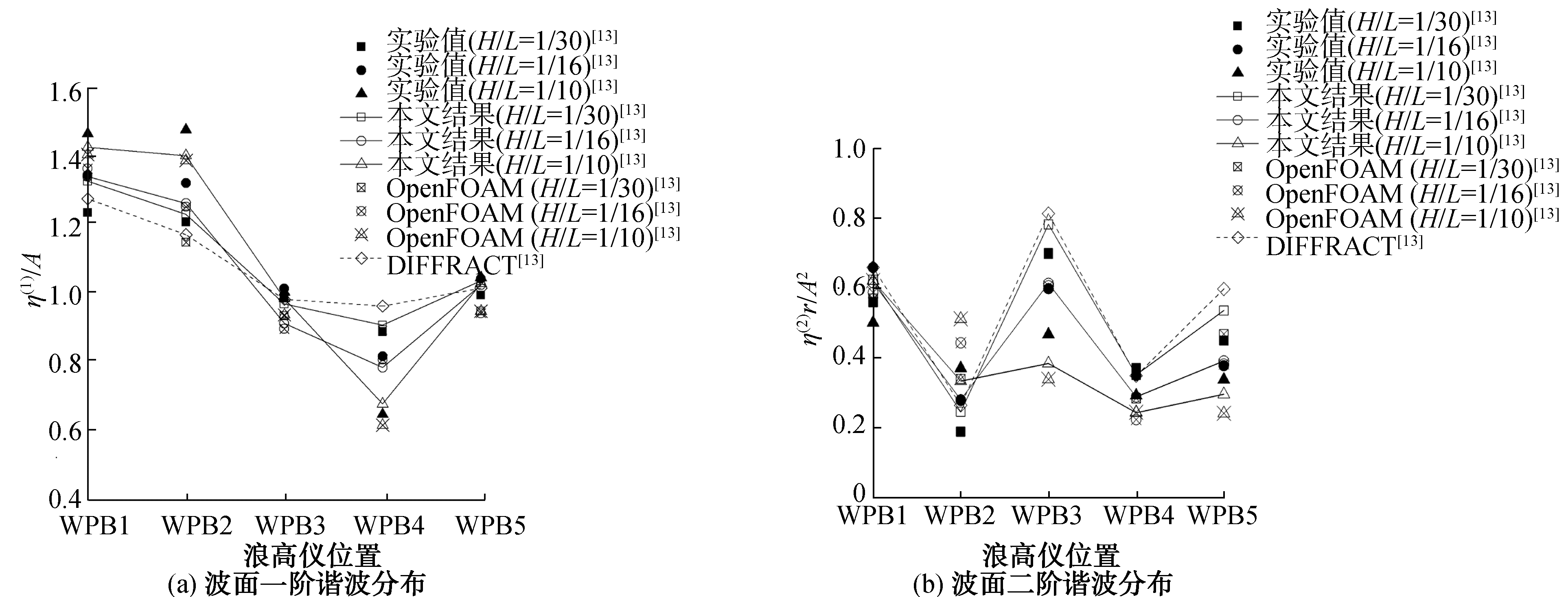
波面信号的一阶、二阶无因次化计算公式分别为η(1)/A、η(2)r/A2。其中η(1)、η(2)分别代表波面谐波分析后的一阶、二阶值。不同的非线性入射波下WPB1~WPB5处波面一阶、二阶谐波结果的空间分布分别可见图 11(a)、11(b)。
|
Download:
|
| 图 11 波面一、二阶谐波分布(T=9 s) Fig. 11 Distribution of the first and second wave surface elevation harmonic (T=9 s) | |
由图 11可知,波面谐波大小与入射波非线性大小有关。迎浪位置WPB1、WPB2处受波浪非线性影响较大。随着入射波非线性增强,一阶谐波值会变大。由于波面的二阶值与波幅的平方相比很小,二阶谐波值会随着非线性增强而变小。势流结果适用于弱非线性(H/L=1/30)波浪爬升的谐波预报。OpenFOAM和本文势粘流耦合的数值结果与试验值吻合良好,可以预报强非线性波浪爬升的谐波预报。
保持波陡H/L=1/16不变,比较在不同入射波周期时圆柱周围波面的一、二阶波面谐波值,分别见图 12和13。

|
Download:
|
| 图 12 波面一阶谐波比较(H/L=1/16) Fig. 12 Wave surface elevation comparison of the first order harmonic (H/L=1/16) | |
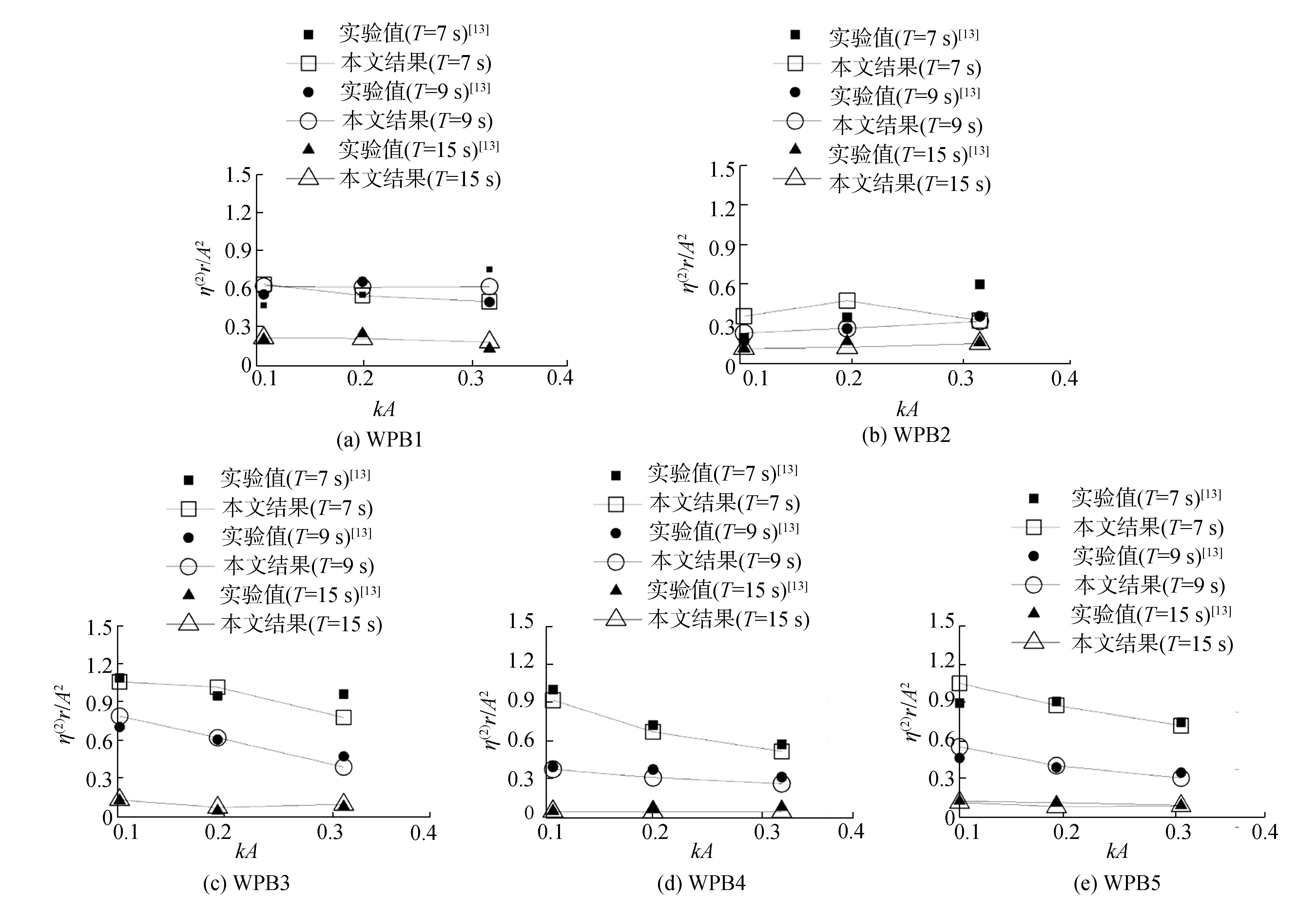
|
Download:
|
| 图 13 波面二阶谐波比较 Fig. 13 Wave surface elevation comparison of the second order harmonic | |
由图 12可知,在相同波陡,不同波长的入射波作用下,势流和粘流对波面一阶谐波的预报结果与试验值吻合良好。由图 13知,由于圆柱对短波反射作用较强,短波下波面二阶谐波值较大。在长波T=15 s时的二阶波面谐波值接近于零。
3.3 圆柱受力分析以T=9 s为例比较不同波陡(H/L=1/16)、不同周期(T=9 s)下圆柱波浪力,分别见图 14和图 15。

|
Download:
|
| 图 14 不同波陡下圆柱受力结果 Fig. 14 Force results of the cylinder under different wave steepness | |

|
Download:
|
| 图 15 不同周期下圆柱受力结果 Fig. 15 Force results of the cylinder under different wave periods | |
由图 14可知,相同来波周期下,波陡越大圆柱受力越大。由图 15可知,在相同的波陡下,周期大的入射波波高大,圆柱受力越大。并且Fz的平均值会随着波高变大向下偏移,对圆柱有向下“拍击”的作用。
3.4 效率比较以及圆柱绕射流场分析本文采用的势粘流耦合方法模拟圆柱体波浪爬升问题,相比全粘流方法可以减小计算所需网格数。以T=9 s,波陡H/L=1/16为例,在相同的网格设置下,本文方法所需网格数为1.14×106,而全粘流方法由于要增加计算域的长度,需要的网格数约为1.41×106。
以波浪周期T=9 s,波陡H/L=1/16为例,每隔1/4周期研究圆柱周围波浪爬升过程中波面的绕射变化,见图 16。当t=T0时, 波峰传到圆柱上游位置,由于壁面的反射作用,形成的向上游传播的圆弧形反射波在与上游入射波波峰叠加,导致圆柱上游位置出现波面爬升,见图 16(a)。当t=T0+T/4时, 波峰到达圆柱位置,圆柱近壁面WPB1处达到最大的波面爬升高度。除了向上游传播的圆弧形反射波外,圆柱两侧会出现对称的相对扇形“凹陷”,形成向下游传播的散射波,见图 16(b)。当t=T0+T/2时,波峰到达圆柱下游位置,入射波与向下游传播的散射波叠加,在圆柱下游位置形成较大波面爬升,见图 16(c)。当t=T0+3T/4时,波谷到达圆柱位置,又开始形成向上游传播的圆弧形反射波,见图 16(d)。

|
Download:
|
| 图 16 圆柱周围波面演化过程 Fig. 16 Evolution of scattered wave around column | |
1) 势流方法适用于弱非线性工况(H/L=1/30)下的波浪爬升预报。势粘流耦合方法以及OpenFOAM的数值预报结果与试验吻合良好,但OpenFOAM计算需要更多的网格数。
2) 入射波的非线性越强,圆柱壁面的波浪爬升就越明显。迎浪位置WPB1、WPB2处的波面谐波值受波浪非线性影响较大。由于圆柱的反射效应,短波下波面二阶谐波值较大。而长波T=15 s时的二阶波面谐波值接近于零。
3) 圆柱收到的波浪力与来波的波高有关,波高越大,受力越大。并且随着垂向力的平均值会随着波高变大向下偏移,对圆柱有向下“拍击”的作用。
4) 在相同的网格设置下,相对于本文势粘流耦合方法,全粘流方法计算所需要的网格更多。
本文的数值模拟设置和网格参数可作为波浪爬升数值模拟的参考。后续可在此基础上对多个圆柱的波浪爬升问题进行研究。
| [1] |
单铁兵, 杨建民, 李欣, 等. 深海平台立柱周围波浪非线性爬升研究进展[J]. 海洋工程, 2012, 30(1): 151-160. SHAN Tiebing, YANG Jianmin, LI Xin, et al. Review of the research on non-linear wave run-up around columns of deepwater platform[J]. The ocean engineering, 2012, 30(1): 151-160. DOI:10.3969/j.issn.1005-9865.2012.01.022 (  0) 0)
|
| [2] |
MACCAMY R C, FUCHS R A. Wave forces on piles: a diffraction theory[R]. Washington DC: Corps of Engineering, Beach Erosion Board, 1954.
(  0) 0)
|
| [3] |
KRIEBEL D L. Nonlinear wave interaction with a vertical circular cylinder. Part Ⅱ:wave run-up[J]. Ocean engineering, 1992, 19(1): 75-99. DOI:10.1016/0029-8018(92)90048-9 (  0) 0)
|
| [4] |
MORRIS-THOMAS M, THIAGARAJAN K, KROKSTAD J. An experimental investigation of wave steepness and cylinder slenderness effects on wave run-up[C]//Proceedings of the ASME 200221st International Conference on Offshore Mechanics and Arctic Engineering. Norway, 2002: 244-253. http://proceedings.asmedigitalcollection.asme.org/proceeding.aspx?articleid=1576765
(  0) 0)
|
| [5] |
STANSBERG C T, KRISTIANSEN T. Non-linear scattering of steep surface waves around vertical columns[J]. Applied ocean research, 2005, 27(2): 65-80. DOI:10.1016/j.apor.2005.11.004 (  0) 0)
|
| [6] |
单铁兵.波浪爬升的机理性探索和半潜式平台气隙响应的关键特性研究[D].上海: 上海交通大学, 2013. SHAN Tiebing. Research on the mechanism of wave run-up and the key characteristics of air-gap response of semi-submersible[D]. Shanghai: Shanghai Jiao Tong University, 2013. http://cdmd.cnki.com.cn/Article/CDMD-10248-1014008382.htm (  0) 0)
|
| [7] |
YOON S H, KIM D H, SADAT-HOSSEINI H, et al. High-fidelity CFD simulation of wave run-up for single/multiple surface-piercing cylinders in regular head waves[J]. Applied ocean research, 2016, 59: 687-708. DOI:10.1016/j.apor.2015.08.008 (  0) 0)
|
| [8] |
KIM J, JAIMAN R, COSGROVE S, et al. Numerical wave tank analysis of wave run-up on a truncated vertical cylinder[C]//Proceedings of the ASME 201130th International Conference on Ocean, Offshore and Arctic Engineering. The Netherlands, 2011: 805-814. https://cpb-us-w2.wpmucdn.com/blog.nus.edu.sg/dist/5/8051/files/2017/06/OMAE2011-50283-2ik8n8u.pdf
(  0) 0)
|
| [9] |
KIM J, O'SULLIVAN J, READ A. Ringing analysis of a vertical cylinder by Euler overlay method[C]//Proceedings of the ASME 201231st International Conference on Ocean, Offshore and Arctic Engineering. Rio de Janeiro, Brazil, 2012: 855-866. http://proceedings.asmedigitalcollection.asme.org/proceeding.aspx?articleid=1732900
(  0) 0)
|
| [10] |
BØCKMANN A, PÂKOZDI C, KRISTIANSEN T, et al. An experimental and computational development of a benchmark solution for the validation of numerical wave tanks[C]//Proceedings of the ASME 201433rd International Conference on Ocean, Offshore and Arctic Engineering. San Francisco, California, USA, 2014: V002T08A092. https://www.researchgate.net/publication/267038104_An_Experimental_and_Computational_Development_of_a_Benchmark_Solution_for_the_Validation_of_Numerical_Wave_Tanks
(  0) 0)
|
| [11] |
BAQUET A, KIM J, HUANG Z J. Numerical modeling using CFD and potential wave theory for three-hour nonlinear irregular wave simulations[C]//Proceedings of the ASME 201736th International Conference on Ocean, Offshore and Arctic Engineering. Trondheim, Norway, 2017: V001T01A002. http://proceedings.asmedigitalcollection.asme.org/proceeding.aspx?articleid=2655250
(  0) 0)
|
| [12] |
ITTC. Final report and recommendations to the 27th ITTC[R]. Copenhagen, Denmark: ITTC, 2014.
(  0) 0)
|
| [13] |
SUN L, ZANG J, CHEN L, et al. Regular waves onto a truncated circular column:a comparison of experiments and simulations[J]. Applied ocean research, 2016, 59: 650-662. DOI:10.1016/j.apor.2016.03.011 (  0) 0)
|
| [14] |
STAR-CCM+. User Guide version 12.02[J]. Siemens PLM Software.
(  0) 0)
|
| [15] |
赵彬彬, 段文洋. 层析水波理论-GN波浪模型[M]. 北京: 清华大学出版社, 2014. ZHAO Binbin, DUAN Wenyang. Fluid sheets wave theory-GN wave model[M]. Beijing: Tsinghua University Press, 2014. (  0) 0)
|
| [16] |
唐鹏, 于定勇, BAI Wei, 等. 海洋工程中直立圆柱波浪爬升问题的数值研究[J]. 中国海洋大学学报, 2016, 46(10): 116-122. TANG Peng, YU Dingyong, BAI Wei, et al. Numerical simulation of wave run-up on cylindrical offshore structures[J]. Periodical of Ocean University of China, 2016, 46(10): 116-122. (  0) 0)
|
 2019, Vol. 40


