面齿轮传动是一种新型的齿轮传动形式。因其具有转矩分流、承载能力强、重合度大等优点,早在20世纪50年代,国外学者Emilio和Sarri.O.E等就针对正交面齿轮齿根根切问题开展了研究。Litvin等[1]分析了面齿轮的啮合原理、接触齿面的接触轨迹及面齿轮的齿面方程。Litvin还将面齿轮传动应用于Apache直升机的动力分扭传输系统中[2]。Michele等[3]在考虑面齿轮啮合传动两轴线相交或交错的不同形式下,给出了面齿轮齿间载荷分配方法。Barone等[4]基于ANSYS对面齿轮三齿模型进行了加载分析,给出了轮齿的接触应力、弯曲应力及其他性能参数,并研究了含有安装误差模型和小轮修形后的加载分析。朱如鹏等[5-9]对面齿轮传动开展了大量研究,主要包括:面齿轮的几何设计、面齿轮加工基本原理及仿真分析等。方宗德等[10-12]研究了斜齿面齿轮的齿顶变尖、根切以及面齿轮副拓扑修形设计及啮合性能等问题。目前国内外对于正交面齿轮齿根过渡曲面的理论研究成果较少,齿根过渡曲面对正交面齿轮弯曲强度影响的研究未见报道。
本文依据面齿轮加工啮合原理和插齿理论齿廓包络面方程,建立正交面齿轮理论齿廓,导出齿根过渡曲面方程,并分别给出齿顶尖角插齿刀和齿顶圆角插齿刀范成加工所切制面齿轮的齿根过渡曲面。文中还以内切抛物线理论为基础,给出了正交面齿轮轮齿的最大弯曲应力位置。最后利用ANSYS有限元软件研究了齿根过渡曲面对正交面齿轮弯曲强度的影响并验证理论分析的正确性。
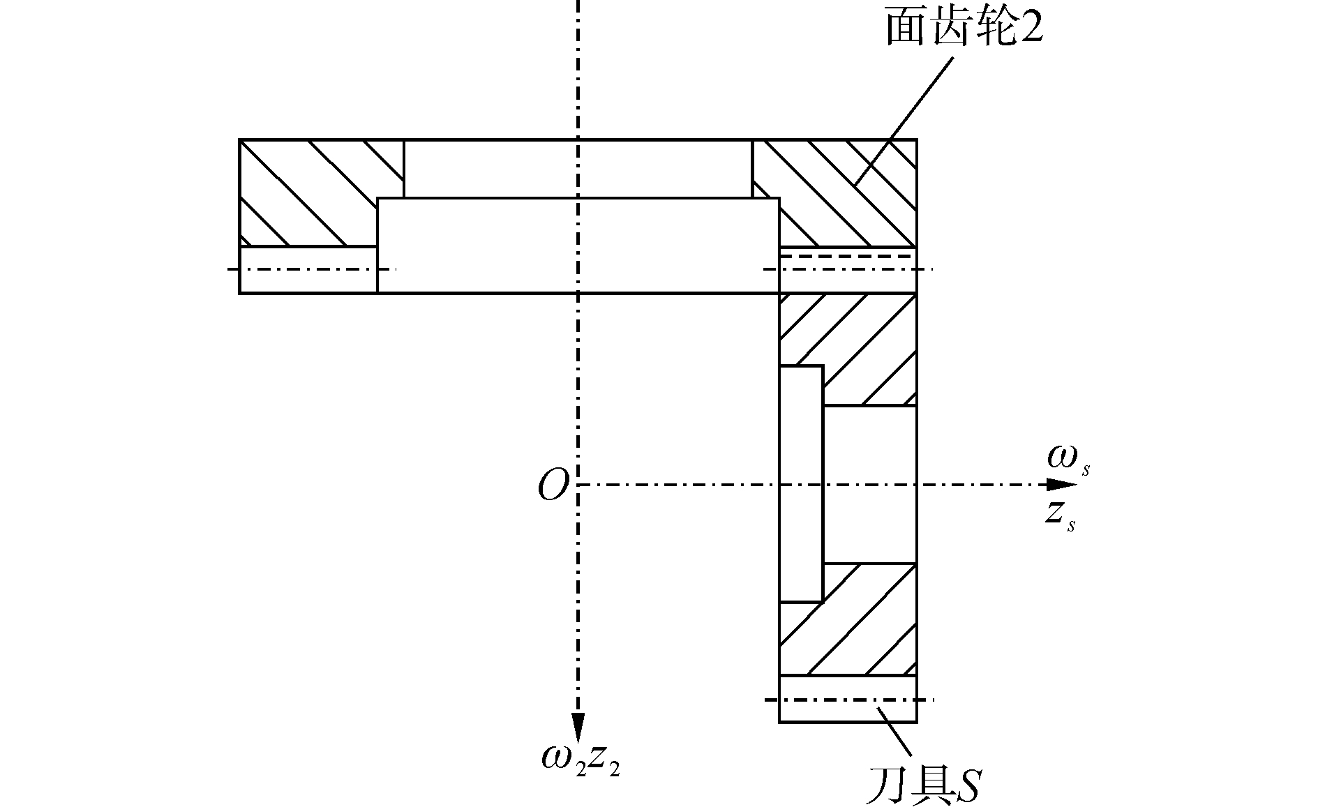
1 正交面齿轮几何模型 1.1 加工坐标系与刀具齿面方程的建立正交面齿轮传动是一种圆柱齿轮与圆锥齿轮相啮合的齿轮传动。正交面齿轮齿面的插齿加工是基于插齿刀与被加工面齿轮的范成运动而切制的,其加工啮合原理如图 1所示[5]。根据面齿轮的包络原理,现利用四个标架对正交面齿轮的啮合传动进行分析,SS0(OS0XS0YS0ZS0)和S20(O20X20Y20Z20)是两个定标架;SS(OSXSYSZS)是与刀具S固联的动标架,随刀具旋转;S2(O2X2Y2Z2)是与正交面齿轮2固联的动标架,随面齿轮2旋转。ZS0和ZS是刀具旋转轴,Z20和Z2是面齿轮旋转轴,其交点为O。ZS0(ZS)与Z20(Z2)夹角γ=90°,如图 2所示。

|
Download:
|
| 图 1 正交面齿轮加工啮合示意图 Fig. 1 Schematic diagram of processing gear of orthogonal face gear | |

|
Download:
|
| 图 2 正交面齿轮加工坐标系 Fig. 2 Machining coordinate system of orthogonal face gear | |
根据图 2,由标架SS到标架S2的坐标变换矩阵可表示为
| $ \begin{array}{l} \;\;\;\;\;\;{M_{2, S}} = {M_{2, 20}}{M_{20, S0}}{M_{S0, S}} = \\ \left[ {\begin{array}{*{20}{c}} {\cos {\varphi _2}\cos {\varphi _s}}&{ - \sin {\varphi _2}\cos {\varphi _2}}&{ - \sin {\varphi _2}}&0\\ { - \cos {\varphi _s}\sin {\varphi _2}}&{\sin {\varphi _s}\sin {\varphi _2}}&{ - \cos {\varphi _2}}&0\\ {\sin {\varphi _s}}&{\cos {\varphi _s}}&0&0\\ 0&0&0&1 \end{array}} \right] \end{array} $ | (1) |
式中:φs为刀具S的转角,φ2为面齿轮2的转角。
建立插齿刀轮齿齿面各个参数之间的关系,如图 3所示[5]。在与刀具S固联的动标架SS(OSXSYSZS)下,刀具齿面方程为

|
Download:
|
| 图 3 刀具齿面参数 Fig. 3 Parameters of the tool tooth surface | |
| $ \begin{array}{l} \;\;\;{\mathit{\boldsymbol{r}}_s}({u_{s, }}{\theta _s}) = {[{x_s}\;\;{y_s}\;\;{z_s}\;\;t]^{\rm{T}}} = \\ \left[ {\begin{array}{*{20}{c}} { \pm {r_{bs}}[\sin ({\theta _{s0}} + {\theta _s}) - {\theta _s}\cos ({\theta _{s0}} + {\theta _s})]}\\ { - {r_{bs}}[\cos ({\theta _{s0}} + {\theta _s}) + {\theta _s}\sin ({\theta _{s0}} + {\theta _s})]}\\ {{u_s}}\\ 1 \end{array}} \right] \end{array} $ | (2) |
式中:θS0=π/(2Ns)-invαS,rbs为刀具基圆半径,θs为齿向角,θs0为齿槽角,us为刀具Z方向变量,Ns为刀具齿数,αs为刀具压力角,invαs为渐开线函数。式(2)中“±”号分别与渐开线γ-γ与β-β相对应。
刀具齿面幺法矢ns为
| $ {\mathit{\boldsymbol{n}}_s} = \left[ {\begin{array}{*{20}{c}} {{n_{sx}}}\\ {{n_{sy}}}\\ {{n_{sz}}} \end{array}} \right] = \frac{{\partial {\mathit{\boldsymbol{r}}_s}/\partial {\theta _s} \times \partial {\mathit{\boldsymbol{r}}_s}/\partial {u_s}}}{{\left| {\partial {\mathit{\boldsymbol{r}}_s}/\partial {\theta _s} \times \partial {\mathit{\boldsymbol{r}}_s}/\partial {u_s}} \right|}} =\\ \left[ {\begin{array}{*{20}{c}} { \mp \cos ({\theta _{s0}} + {\theta _s})}\\ { - \sin ({\theta _{s0}} + {\theta _s})}\\ 0 \end{array}} \right] $ | (3) |
设刀具齿面上的任意一点N(xs, ys, zs),其径矢rs为
| $ {\mathit{\boldsymbol{r}}_s} = {[{x_s}\;\;{y_s}\;\;{z_s}]^{\rm{T}}} = {x_s}{\mathit{\boldsymbol{i}}_s} + {y_s}{\mathit{\boldsymbol{j}}_s} + {z_s}{\mathit{\boldsymbol{k}}_s} $ | (4) |
式中is、js、ks为标架Ss中三个方向幺矢。则N点在两齿面的相对速度矢v(S, 2)为
| $ {\mathit{\boldsymbol{v}}^{(S, 2)}} = \left[ \begin{array}{l} {v_x}^{(S, 2)}\\ {v_y}^{(S, 2)}\\ {v_z}^{(S, 2)} \end{array} \right] = {\omega _s}\left[ {\begin{array}{*{20}{c}} { - {y_s} - {z_s}{q_{2s}}\cos {\varphi _s}}\\ {{x_s} + {z_s}{q_{2s}}\sin {\varphi _s}}\\ {{q_{2s}}({x_s}\cos {\varphi _s} - {y_s}\sin {\varphi _s})} \end{array}} \right] $ | (5) |
式中:ωs为刀具S角速度,q2 s为正交面齿轮齿数与刀具齿数比。
由齿面啮合原理知
| $ {\mathit{\boldsymbol{n}}_s}\cdot{\mathit{\boldsymbol{v}}^{(S, 2)}} = 0 $ | (6) |
将式(2)、(3)、(5)代入式(6),可得出正交面齿轮啮合方程
| $ f({\theta _s}, {\varphi _s}, {u_s}) = {r_{bs}} - {u_s}{q_{2s}}\cos {\varphi _\theta } = 0 $ | (7) |
式中φθ=φs±(θs0+θs)。
联立式(1)、(7)得到正交面齿轮齿面方程:
| $ \left\{ \begin{array}{l} {\mathit{\boldsymbol{x}}_2} = {\mathit{\boldsymbol{r}}_{bs}}\left[ {\cos {\varphi _2}\left( {(\sin {\varphi _\theta } \mp {\theta _s}\cos {\varphi _\theta }) - \frac{{\sin {\varphi _2}}}{{{q_{2s}}\cos {\varphi _\theta }}}} \right)} \right]\\ {y_2} = - {\mathit{\boldsymbol{r}}_{bs}}\left[ {\sin {\varphi _2}\left( {(\sin {\varphi _\theta } \mp {\theta _s}\cos {\varphi _\theta }) + \frac{{\cos {\varphi _2}}}{{{q_{2s}}\cos {\varphi _\theta }}}} \right)} \right]\\ {z_2} = - {r_{bs}}(\cos {\varphi _\theta } \pm {\theta _s}\sin {\varphi _\theta }) \end{array} \right. $ | (8) |
式中φ2=q2 sφs。
1.3 正交面齿轮齿根过渡曲面及其齿廓的生成带有齿顶尖角和带有齿顶圆角的插齿刀的结构示意图分别如图 4 (a)、(b)所示。

|
Download:
|
| 图 4 两种插齿刀结构示意图 Fig. 4 Schematic diagram of the structure of gear slotting cutter | |
在图 4 (b)中,构建坐标系S0和Sos。ra0是插齿刀齿顶圆半径,r0是刀具分度圆半径,rbo是刀具基圆半径。插齿刀齿顶圆角的曲率中心为Oc,圆弧和渐开线相切于点A,A点的向径为rA,圆角的半径为rc,A点处渐开线压力角为αA。
由包络原理得正交面齿轮过渡曲面
| $ \left\{ \begin{array}{l} {r_{2t}}({\varphi _s}, {\gamma _A}, {u_s}) = [{M_{2t, t}}]{r_t}({\gamma _A}, {u_s})\\ \;\;\;\;\;\;\;\;f({u_s}, {\varphi _s}, {\gamma _A}) = 0 \end{array} \right. $ | (9) |
式中:f(us,θs,γA)=nt·v(t, 2 t)为啮合方程,nt(γA, us)为圆角曲面法矢M2 t, t为标架St到S2 t的坐标变换矩阵。
则可得出由带有齿顶圆角插齿刀所切制的正交面齿轮的过渡曲面方程
| $ \left\{ \begin{array}{l} {X_{2t}} = {r_c}\cos {\varphi _2}\left( {\cos B - \cos A} \right) + {r_A}\cos {\varphi _2}\sin C - \\ \;\;\; - \frac{{{r_A}\sin {\varphi _2}\cos ({\alpha _A} + {\gamma _A}) - {r_A}\sin {\varphi _2}\cos {\alpha _A}}}{{{q_{2s}}\left( {\cos A - \cos B} \right)}}\\ {Y_{2t}} = {r_c}\sin {\varphi _2}\left( {\cos B - \cos A} \right) - {r_A}\sin {\varphi _2}\sin C - \\ \;\;\;\;\frac{{{r_A}\cos {\varphi _2}\cos ({\alpha _A} + {\gamma _A}) - {r_A}\cos {\varphi _2}\cos {\alpha _A}}}{{{q_{2s}}\left( {\cos A - \cos B} \right)}}\\ {Z_{2t}} = {r_c}\sin A - {r_c}\sin B - {r_A}\cos C \end{array} \right. $ | (10) |
式中:A=αA-φ-ψ-τ-φs,B=αA+γA-φ-ψ-τ-φs,C=φ+ψ+τ+φs。
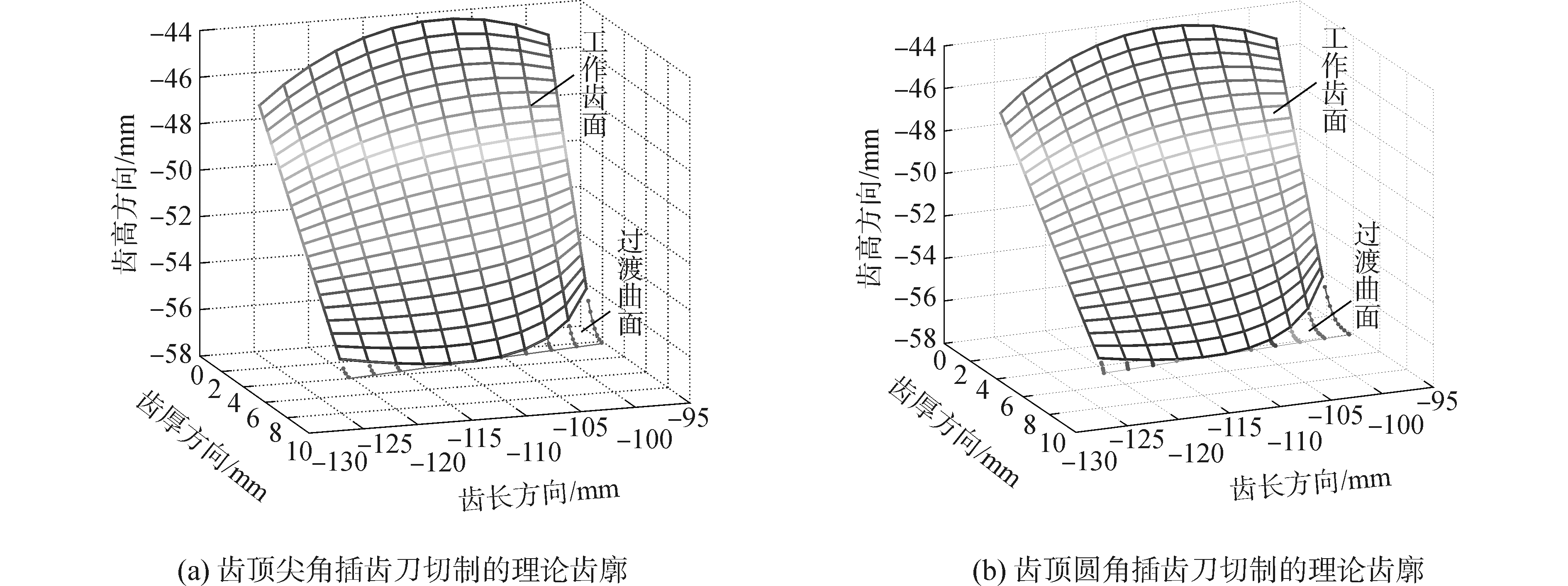
在刀具设计手册中,对于模数2≤m≤8的插齿刀,其齿顶圆角为0.15≤rc≤0.4mm[13],本文取rc=0.3 mm。根据上述正交面齿轮齿面数学模型,基于Matlab软件得到两种插齿刀切制的面齿轮理论齿廓,如图 5所示。其主要参数见表 1。

|
Download:
|
| 图 5 正交面齿轮插齿理论齿廓 Fig. 5 Theoretical gear profile of orthogonal face gear by pinion cutter | |
| 表 1 面齿轮主要参数 Tab.1 Main parameters of orthogonal face gear |
将两种不同齿面结构插齿刀切制的正交面齿轮理论齿廓进行对比,如图 6所示。可以看出,齿顶圆角插齿刀所切制正交面齿轮的齿根过渡曲面要比齿顶尖角插齿刀切制的齿根过渡曲面要平坦,即两者的曲率是不同的。采用带齿顶圆角的插齿刀加工得到的面齿轮过渡曲面的曲率较大。

|
Download:
|
| 图 6 两种插齿刀切制的正交面齿轮齿根过渡曲面 Fig. 6 Two kinds of tooth root transition curved surface cut by angle cutter & corner cutter | |
以上正交面齿轮齿面方程通过数值计算得到齿面离散数据点,在Pro/E软件中通过边界混合即可构建两种正交面齿轮齿廓及三维实体模型,如图 7所示。

|
Download:
|
| 图 7 正交面齿轮全齿实体模型 Fig. 7 3D model of orthogonal face gear | |
正交面齿轮的轮齿边界齿廓线是不一样的,因此面齿轮轮齿与一般可作为悬臂梁分析的齿轮轮齿不同,现分析其轮齿齿面上的危险点位置。首先确定与齿长方向垂直且经过齿面受载位置的截面。如图 8所示,集中载荷在面齿轮的齿顶线上,其中γ为法向力Fn和x轴之间夹角,且Fn相切于圆柱齿轮基圆。

|
Download:
|
| 图 8 正交面齿轮受力图 Fig. 8 Force diagrams of orthogonal face gear | |
经推导计算,正交面齿轮承受的最大弯曲应力位于轮齿齿面上端,而不是像多数其他类型齿轮位于齿根过渡曲面附近。其分析截面齿廓曲线方程为
| $ \left\{ \begin{array}{l} C = - {r_{bs}}\left[ {\sin {\varphi _2}(\sin {\varphi _\theta } \mp {\theta _s}\cos {\varphi _\theta }) + \frac{{\cos {\varphi _2}}}{{{q_{2s}}\cos {\varphi _\theta }}}} \right]\\ x = {r_{bs}}\left[ {\cos {\varphi _2}(\sin {\varphi _\theta } \mp {\theta _s}\cos {\varphi _\theta }) - \frac{{\sin {\varphi _2}}}{{{q_{2s}}\cos {\varphi _\theta }}}} \right]\\ y = {r_{bs}}(\cos {\varphi _\theta } \pm {\theta _s}\sin {\varphi _\theta }) - {r_{bs}} - \frac{d}{2}\tan \gamma \end{array} \right. $ | (11) |
式中:C为常数,其值与正交面齿轮齿顶受载位置有关;d为面齿轮轮齿各分析截面的齿顶长度。
由于式(11)较繁,不易直接通过其求解出正交面齿轮弯曲危险截面。可采用前文正交面齿轮齿面数据点形成的方法,通过正交面齿轮传动的啮合方程来解出φs和θs之间的关系。根据正交面齿轮的啮合条件可以求解出θs的取值范围,在这个范围中取i个离散值,于此同时,根据φs和θs之间的关系,可以得到对应φs的i个离散值。将这些值对应地代入式(11),可以求得相应面齿轮齿廓上的i个点的坐标(x, y)。通过曲线拟合将这些离散坐标点拟合成有一定精度的函数y=f(x)。
根据上述方法,本文利用Matlab软件编制了正交面齿轮齿面最大弯曲应力点的程序。其中重要的参数为:模数m=5 mm,齿数N2=40。结果如表 2所示。
| 表 2 面齿轮齿面最大弯曲应力点 Tab.2 The maximum bending stress of tooth surface |
将表 2中数据导入Matlab软件可得到正交面齿轮齿面承受最大弯曲应力位置图,如图 9所示。可以看出正交面齿轮承受的最大弯曲应力位置在沿齿高方向齿面的上半部分。

|
Download:
|
| 图 9 正交面齿轮齿面承受最大弯曲应力位置 Fig. 9 Maximum bending stress position on tooth surface | |
对本文给定参数所建立的两种不同正交面齿轮的三维实体模型,基于ANSYS软件对其模型进行有限元仿真分析,计算其相应工况下的弯曲应力及应力分布状态。综合考量计算精度和计算效率,确定采用正交面齿轮的三齿模型进行有限元分析,网格模型的单元类型采用八节点六面体单元并通过结构化分网技术对其进行网格划分。划分节点数为131 881个,单元数为29 799个。
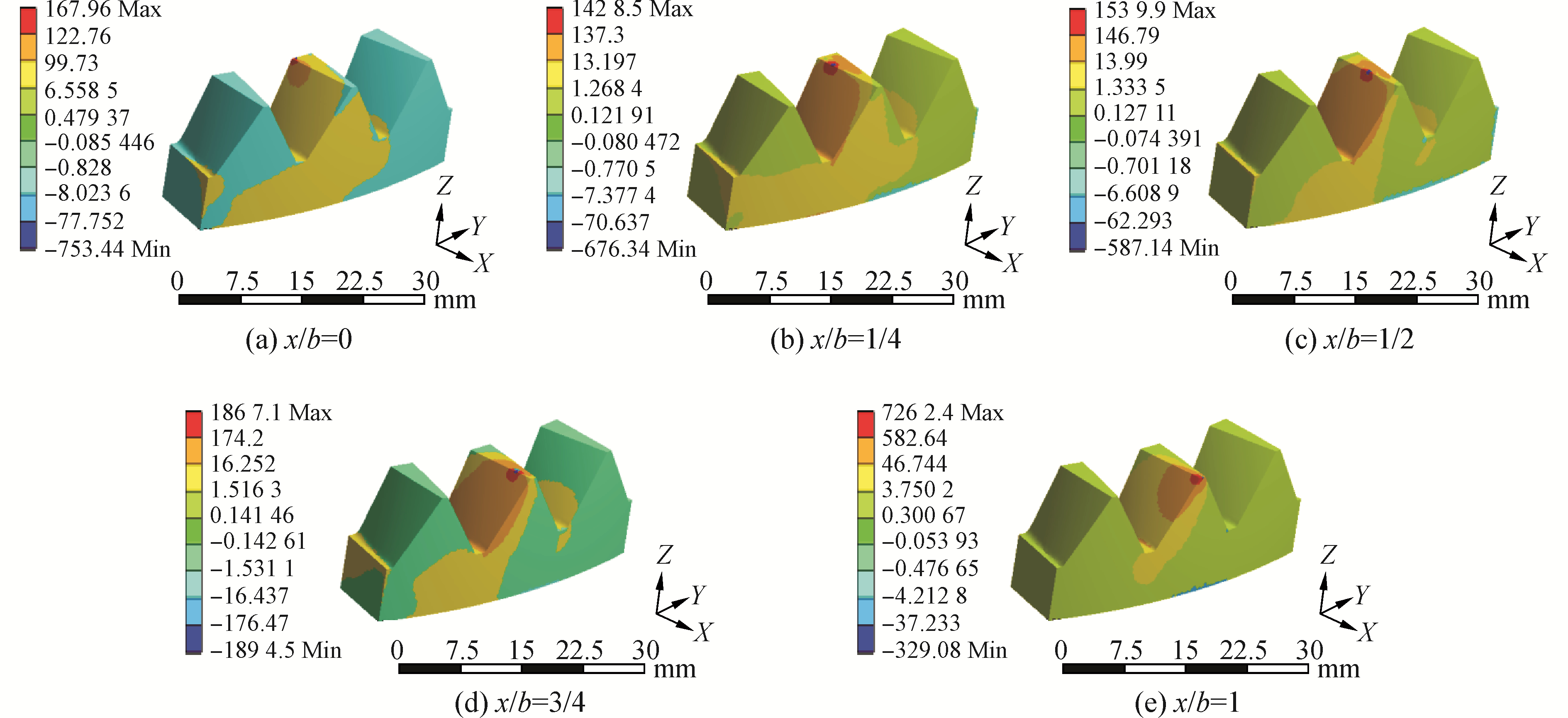
边界条件为在正交面齿轮三齿模型的底面施加固定约束,以限制其全部自由度;同时为了减小仿真所采用三齿模型对正交面齿轮弯曲强度的影响,本文对其两个周向截面施加对称约束。考虑到正交面齿轮在传动的过程中其齿面上的受载位置是不断变化的,为确定轮齿的危险截面,需分析其最不利的受力状况,即啮合点达到正交面齿轮轮齿的齿顶处时,现对三齿正交面齿轮齿顶处施加集中载荷。载荷的加载位置分别为x/b=0、1/4、1/2、3/4、1处,其中b为正交面齿轮轮齿宽度,为载荷施加位置到面齿轮内径的距离。根据实际工况,面齿轮齿顶集中载荷设置为1 000 N,载荷的加载方向与正交面齿轮相啮合圆柱齿轮的基圆相切,并通过正交面齿轮齿面方程参数θs、θs0和φ予以确定。
对所建立的有限元分析模型进行求解,即可得出两种不同插齿刀所切制正交面齿轮轮齿的弯曲应力及应力分布。采用两种插齿刀切制的正交面齿轮轮齿弯曲应力分别对比如图 10、图 11所示。

|
Download:
|
| 图 10 尖角插齿刀切制的面齿轮弯曲应力云图 Fig. 10 Bending stress nephogram of face gear by angle cutter | |

|
Download:
|
| 图 11 圆角插齿刀切制的面齿轮弯曲应力云图 Fig. 11 Bending stress nephogram of face gear by corner cutter | |
图 10和图 11给出了两种正交面齿轮在给定的边界条件以及载荷作用下轮齿的弯曲应力分布状态,从图中可以看出,在正交面齿轮传动的过程中,对于最不利的受载状况,其载荷施加位置分别为x/b=0、1/4、1/2、3/4、1处时,正交面齿轮所承受的最大弯曲应力位置始终处于沿齿高方向齿面的上半部分,且在面齿轮轮齿的高度方向上其弯曲应力值由齿顶向齿根逐渐减小,当载荷作用点沿齿长方向向轮齿的两端移动时,最大弯曲应力位置会同时随着加载位置向轮齿的两端移动并沿齿高方向向齿顶移动。由此可见,正交面齿轮齿面承受最大弯曲应力位置的有限元分析结果与上文理论分析结果是一致的。为定量比较齿根过渡曲面对正交面齿轮弯曲强度的影响大小,现将两种正交面齿轮的有限元仿真分析结果数据导入Matlab软件,拟合得到其弯曲应力变化曲线,如图 12所示。从图中可以看出,带有齿顶圆角插齿刀所切制的正交面齿轮的最大弯曲应力小于齿顶尖角插齿刀切制的正交面齿轮。进一步说明了齿顶圆角插齿刀切制的齿根过渡曲面对正交面齿轮的抗弯强度有一定程度的提高。

|
Download:
|
| 图 12 两种正交面齿轮的弯曲应力曲线 Fig. 12 Bending stress curves of two kinds of orthogonal face gears | |
1) 根据面齿轮的加工啮合原理和插齿理论齿廓包络面方程,研究了正交面齿轮齿根过渡曲面的理论推导过程,并利用Matlab软件和Pro/E软件建立了正交面齿轮的工作齿面和齿根过渡曲面,准确给出了面齿轮的三维实体模型。进而比较了两种插齿刀切制的正交面齿轮齿根过渡曲面的结构,从结构分析了带有齿顶圆角的插齿刀所切制的正交面齿轮的过渡曲面是光滑连续的,不易产生应力集中现象,理论上使得其承载能力得到加强。
2) 利用内切抛物线法从理论的角度分析了正交面齿轮轮齿的最大弯曲应力位置,正交面齿轮轮齿在受到作用于齿顶的集中载荷时,其最大弯曲应力位置在沿齿高方向的齿面的上半部分。
3) 基于ANSYS软件验证了理论推导的正确性。通过有限元分析结果可以得出采用齿顶圆角插齿刀切制的正交面齿轮的最大弯曲应力小于采用齿顶尖角插齿刀所切制的面齿轮,即齿顶圆角插齿刀切制的齿根过渡曲面提高了正交面齿轮的弯曲强度。
| [1] |
LITVIN F L. 齿轮几何学与应用理论[M]. 国楷, 叶凌云, 范琳, 等译. 上海: 上海科学技术出版社, 2008: 484-518. LITVIN F L. Gear geometry and applied theory[M]. GUO Kai, YE Lingyun, FAN Lin, et al. Trans. Shanghai: Shanghai Science and Technology Press, 2008: 484-518. (  0) 0)
|
| [2] |
LITVIN F L, FUENTES A, ZANZI C, et al. Face-gear drive with spur involute Pinion:geometry, generation by a worm, stress analysis[J]. Computer methods in applied mechanics and engineering, 2002, 191(25/26): 2785-2813. (  0) 0)
|
| [3] |
GUINGAND M, DE VAUJANY J P, JACQUIN C Y. Quasi-static analysis of a face gear under torque[J]. Computer methods in applied mechanics and engineering, 2005, 194(39/40/41): 4301-4318. (  0) 0)
|
| [4] |
BARONE S, BORGIANNI L, FORTE P. Evaluation of the effect of misalignment and profile modification in face gear drive by a finite element meshing simulation[J]. Journal of mechanical design, 2004, 126(5): 916-924. DOI:10.1115/1.1767818 (  0) 0)
|
| [5] |
朱如鹏, 潘升材, 高德平. 正交面齿轮传动中齿宽设计的研究[J]. 机械科学与技术, 1999, 18(4): 566-567, 569. ZHU Rupeng, PAN Shengcai, GAO Deping. Study of the design of tooth width of right shaft angle face gear drive[J]. Mechanical science and technology, 1999, 18(4): 566-567, 569. (  0) 0)
|
| [6] |
朱如鹏, 高德平. 在面齿轮设计中避免根切和齿顶变尖的设计方法的研究[J]. 中国机械工程, 1999, 10(11): 1274-1276. ZHU Rupeng, GAO Deping. Study on the method of avoiding dedendum undercutting and addendum pointing in face gear design[J]. China mechanical engineering, 1999, 10(11): 1274-1276. DOI:10.3321/j.issn:1004-132X.1999.11.022 (  0) 0)
|
| [7] |
付自平. 正交面齿轮的插齿加工仿真和磨齿原理研究[D]. 南京: 南京航空航天大学, 2006: 89-95. FU Ziping. Research on the simulation of shaping process and grinding principle of orthogonal-shaft face gear[D]. Nanjing: Nanjing University of Aeronautics and Astronautics, 2006: 89-95. http://cdmd.cnki.com.cn/article/cdmd-10287-2006119818.htm (  0) 0)
|
| [8] |
李政民卿, 朱如鹏. 装配偏置误差对正交面齿轮传动接触特性的影响[J]. 航空学报, 2009, 30(7): 1353-1360. LI Zhengminqing, ZHU Rupeng. Impact of assembly deflection error on contact characteristics of orthogonal face gear drive[J]. Acta aeronautica et astronautica sinica, 2009, 30(7): 1353-1360. (  0) 0)
|
| [9] |
李政民卿, 陈宏尚, 朱如鹏. 主要参数对面齿轮传动噪声辐射的影响分析[J]. 航空动力学报, 2015, 30(11): 2803-2809. LI Zhengminqing, CHEN Hongshang, ZHU Rupeng. Influence predictions of base parameters on noise radiations of face gear drives[J]. Journal of aerospace power, 2015, 30(11): 2803-2809. (  0) 0)
|
| [10] |
沈云波, 方宗德, 赵宁, 等. 齿廓方向修形的斜齿面齿轮啮合特性研究[J]. 中国机械工程, 2008, 19(18): 2219-2222. SHEN Yunbo, FANG Zongde, ZHAO Ning, et al. Meshing performance of modified face gear drive with helical pinion in the profile direction[J]. China mechanical engineering, 2008, 19(18): 2219-2222. DOI:10.3321/j.issn:1004-132X.2008.18.018 (  0) 0)
|
| [11] |
崔艳梅, 方宗德, 王星. 考虑安装误差的弧线齿面齿轮承载接触分析[J]. 机械传动, 2015, 39(8): 115-118. CUI Yanmei, FANG Zongde, WANG Xing. Load tooth contact analysis for arc tooth face gear considering assembly misalignment[J]. Journal of mechanical transmission, 2015, 39(8): 115-118. (  0) 0)
|
| [12] |
付学中, 方宗德, 李建华, 等. 面齿轮副小轮拓扑修形设计及啮合性能分析[J]. 哈尔滨工程大学学报, 2016, 37(9): 1281-1286. FU Xuezhong, FANG Zongde, LI Jianhua, et al. Design of topological shape modification of auxiliary pinion of face gears and analysis of meshing performance[J]. Journal of Harbin Engineering University, 2016, 37(9): 1281-1286. (  0) 0)
|
| [13] |
袁俊哲, 刘华明. 刀具设计手册[M]. 北京: 机械工业出版社, 1999: 950-952. YUAN Junzhe, LIU Huaming. Tool design manual[M]. Beijing: China Machine Press, 1999: 950-952. (  0) 0)
|
 2018, Vol. 39


