机器人辅助微创外科手术是通过手术机器人辅助操作,让医生经由患者体表较小切口实施手术的一种先进技术。与传统外科手术相比,具有定位准确、创伤小、恢复时间短等优点,但是也对手术机器人提出了更高的要求,特别是对机器人的末端定位精度提出了更高的要求[1]。目前,手术机器人多为串联机械臂结构,其末端的位置和姿态无法直接测量,常用机器人运动学间接获得。但是在机器人的加工制造、生产装配过程中,运动学实际参数与理论参数存在差异,从而导致末端定位精度低的问题。所以,为了提高手术机器人的末端定位精度,必须对机器人进行运动学参数标定。
机器人运动学参数标定分为4个步骤,即运动学建模、位置姿态测量、参数辨识以及误差补偿。学者针对位姿测量这一步骤开展了很多研究工作。比较常用的方法是基于运动学模型并利用高精度位姿测量设备,如激光跟踪仪[2-3]、三坐标测量机[4-5]、伸缩式球杆仪[6]、Dynacal系统[7]等,得到末端位姿信息用于参数标定。这类方法定位精度高,参数辨识准确,但通常价格十分昂贵,且对工作环境有严格要求。除此之外,基于视觉传感器以及结合其他传感器[8-10]的运动学参数标定也有广泛的应用。这类方法相比于高精密仪器,应用灵活、成本较低,但是相机参数误差会导致定位精度较低的问题。
为了实现手术机器人末端位置较高精度的测量,本文设计一种基于拉线传感器的三维位置检测装置,使用空间解析几何法建立数学模型;搭建标定实验平台,辨识结构参数误差并修正数学模型;建立手术机器人的绝对误差模型和距离误差模型,辨识运动学参数误差并进行实验验证。
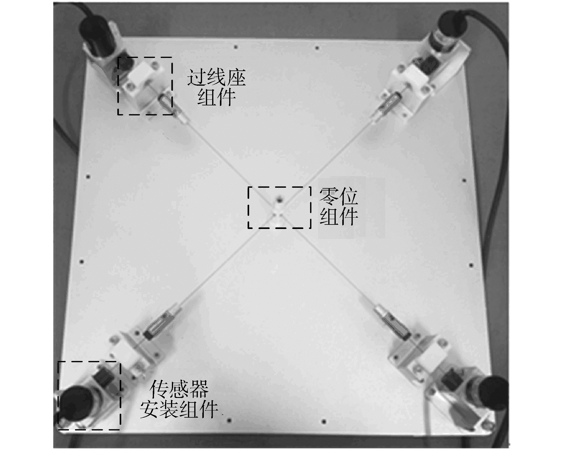
1 位置检测装置数学模型 1.1 结构及硬件设计位置检测装置由传感器安装组件、过线座组件、零位组件及安装底板4个部分组成,如图 1所示。上过线座为韧性树脂,其余加工零件均为2A12铝合金。为保证测量过程中线绳与倒角圆弧的切点不变,上过线座设计R10的内凸圆弧倒角,采用立体光固化成型工艺,加工精度0.1 mm。
|
Download:
|
| 图 1 位置检测装置实验样机 Fig. 1 Position detection device experimental prototype | |
硬件部分由工控机、数据采集卡、拉线传感器等组成,其中数据采集卡为研华PCI-1784U,4路独立32位计数器,最大输入频率8 MHz;拉线传感器为开思KS15MD-400-01-L,量程400 mm,线性误差0.05%,分辨率0.01 mm/脉冲。
1.2 数学模型装置数学模型即建立拉线传感器伸长量与检测点位置坐标之间的关系。选定传感器出线点(A′, B′, C′, D′)、线绳与过线座下切点(A, B, C, D)以及零位点(O)所在平面为基平面,在O点建立基础坐标系X0Y0Z0,如图 2所示。

|
Download:
|
| 图 2 位置检测装置基础坐标系 Fig. 2 Position detection device coordinate system | |
以第1路拉线传感器为对象,建立数学模型。设第1路拉线传感器的伸长量L1,线绳与过线座圆弧倒角上切点E(xe, ye, ze),4路线绳延长线汇交点T(xt, yt, zt),上过线座圆弧倒角圆心Oa,上过线座圆弧倒角半径为r,面TAA′与水平面的夹角θ。根据几何关系可得第1路拉线传感器数学模型为:
| $ \left\{ \begin{array}{l} {L_1} = TE + A{O_a} \cdot \angle A{O_a}E\\ {\left( {{x_e} + {l_a}} \right)^2} + {\left( {{y_e} - r\cos \theta } \right)^2} + {\left( {{z_e} - r\sin \theta } \right)^2} = {r^2}\\ {z_t}{y_e} - {y_t}{z_e} = 0\\ \left( {{x_e} + {l_a}} \right)\left( {{x_t} - {x_e}} \right) + \left( {{y_e} - r\cos \theta } \right)\left( {{y_t} - {y_e}} \right) + \\ \left( {{z_e} - r\sin \theta } \right)\left( {{z_t} - {z_e}} \right) = 0 \end{array} \right. $ | (1) |
根据上述方法,建立其他3路拉线传感器数学模型为:
| $ \left\{ \begin{array}{l} {L_2} = TG + A{O_b} \cdot \angle A{O_b}G\\ {\left( {{x_f} - r\cos \beta } \right)^2} + {\left( {{y_f} - {l_b}} \right)^2} + {\left( {{z_f} - r\sin \beta } \right)^2} = {r^2}\\ {z_t}{x_f} - {x_t}{z_f} = 0\\ {\left( {{x_f} - r\cos \beta } \right)^2}\left( {{x_t} - {x_f}} \right) + \left( {{y_f} - {l_b}} \right)\left( {{y_t} - {y_f}} \right) + \\ {\left( {{z_f} - r\sin \beta } \right)^2}\left( {{z_t} - {z_f}} \right) = 0 \end{array} \right. $ | (2) |
| $ \left\{ \begin{array}{l} {L_3} = TG + A{O_c} \cdot \angle A{O_c}G\\ {\left( {{x_g} - {l_c}} \right)^2} + {\left( {{y_g} - r\cos \delta } \right)^2} + {\left( {{z_g} - r\sin \delta } \right)^2} = {r^2}\\ {z_t}{x_g} - {x_t}{z_g} = 0\\ {\left( {{x_g} - {l_c}} \right)^2}\left( {{x_t} - {x_g}} \right) + {\left( {{y_g} - r\cos \delta } \right)^2}\left( {{y_t} - {y_g}} \right) + \\ {\left( {{z_g} - r\sin \beta } \right)^2}\left( {{z_t} - {z_g}} \right) = 0 \end{array} \right. $ | (3) |
| $ \left\{ \begin{array}{l} {L_4} = TG + A{O_d} \cdot \angle A{O_d}G\\ {\left( {{x_h} - r\cos \sigma } \right)^2} + {\left( {{y_h} - {l_d}} \right)^2} + {\left( {{z_h} - r\sin \sigma } \right)^2} = {r^2}\\ {z_t}{x_h} - {x_t}{z_h} = 0\\ {\left( {{x_h} - r\cos \sigma } \right)^2}\left( {{x_t} - {x_h}} \right) + {\left( {{y_h} - {l_d}} \right)^2}\left( {{y_t} - {y_h}} \right) + \\ {\left( {{z_h} - r\sin \sigma } \right)^2}\left( {{z_t} - {z_h}} \right) = 0 \end{array} \right. $ | (4) |
位置检测装置精度测量实验分为零位实验和相对误差实验。实验样机由标定板、圆柱插头和固定支架组成,如图 3所示。标定板有25个直径3 mm通孔,各孔水平竖直方向间距为30 mm,孔距加工精度为±0.02 mm;圆柱插头通过螺纹与测量头相连接,顶部加工有直径3 mm圆柱。零位实验实验结果如表 1所示。

|
Download:
|
| 图 3 精度测量实验样机 Fig. 3 Precision test experimental prototype | |
| 表 1 零位实验结果 Table 1 Return-to-zero experimental results |
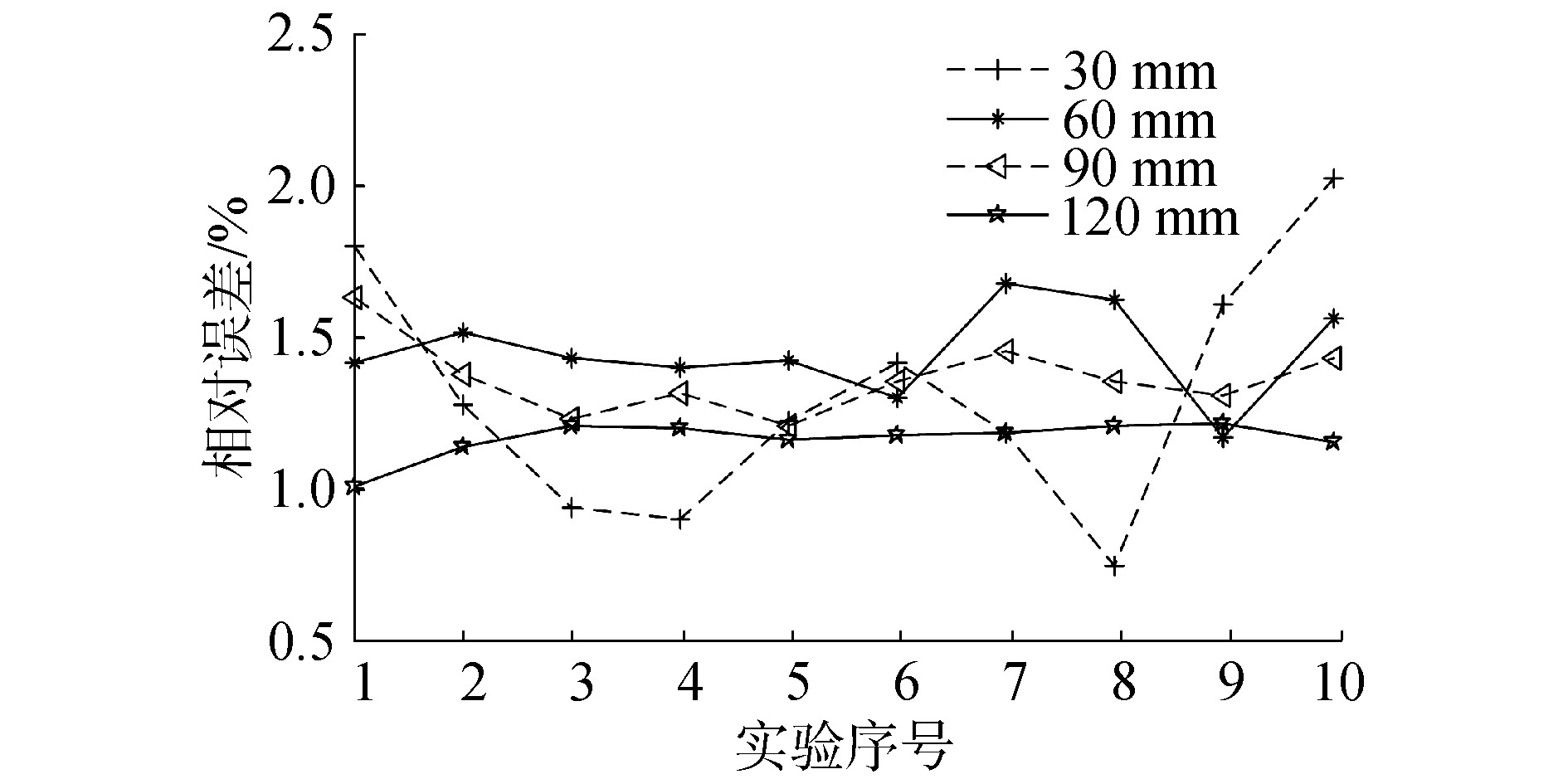
相对误差实验分为2组,一组是相同位置点,另一组是不同位置点,测量距离分别30、60、90和120 mm,实验结果如图 4、图 5所示。

|
Download:
|
| 图 4 相同位置点实验数据 Fig. 4 Relative error of the same point precision test | |
|
Download:
|
| 图 5 不同位置点实验数据 Fig. 5 Relative error of the different points precision test | |
零位实验,X、Y、Z误差平均值分别为0.097、0.136、0.064 mm,方差分别为0.037 96、0.079 27、0.044 32,则装置的零位重复性可以满足使用要求。
相对误差实验,对实验数据均值计算以及相对误差计算,如表 2所示。相同点平均相对误差为1.404 2%,不同点平均相对误差为1.322 4%,综合测量距离平均相对误差为1.363 3%。通过分析可知,装置的精度距离使用要求仍有一定的差距,具体原因如下:由于装置加工、装配误差,导致实际结构参数与理论结构参数存在偏差,从而造成装置数学模型的不准确。因此,采用自标定对装置测量精度做进一步的提高。
| 表 2 精度测量实验数据 Table 2 Accuracy test experimental data |
根据位置检测装置数学模型,线绳与过线座上切点(E, F, G, H),线绳与过线座下切点(A, B, C, D)以及零位点(O)位置坐标对测量点(T)的准确性产生影响,因此选择上述坐标点作为自标定误差模型参数。标定误差模型即在各个所要标定参数后加该变量的误差Δ,用二者和来表示变量的真实值。以式(1)中第3式为例,改写标定误差模型。其他3式建立方法相同,另外3路方程组也按照此方法建立误差方程,联立始末点误差方程以及距离误差方程,得到装置自标定误差模型:
| $ \left( {{z_i} + \Delta {z_t}} \right)\left( {{y_e} + \Delta {y_e}} \right) - \left( {{y_t} + \Delta {y_t}} \right)\left( {{z_e} + \Delta {z_e}} \right) = 0 $ |
利用精度测量实验样机完成40组不同距离实验,排除其中相对误差最高和最低的数据,随机选择10组数据用于求解自标定误差模型,20组数据用于检验自标定结果。利用最小二乘法求解自标定误差模型,获得参数误差,得到补偿后参数如表 3所示。
| 表 3 结构参数误差及补偿 Table 3 Structural parameters error and compensation |
根据补偿后参数,得到修正数学模型,将20组数据代入修正模型中,得到修正模型平均相对误差0.201 1%,原模型平均相对误差1.348 9%,自标定后检测装置的精度大幅提高。
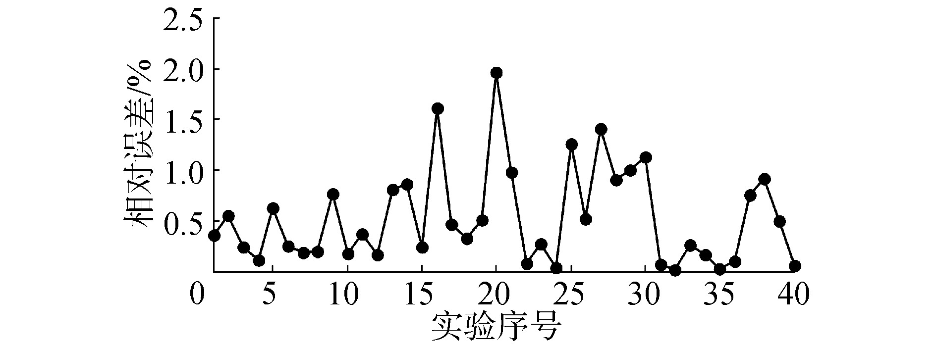
3.3 自标定后精度测量实验使用修正数学模型对装置进行精度测量,30、60、90、120 mm距离各10次,相对误差曲线如图 6所示。自标定后装置平均相对误差为0.530 7%,与原模型的平均相对误差1.363 3%相比,装置测量精度提升61.07%,满足使用要求。
|
Download:
|
| 图 6 自标定后精度测量相对误差 Fig. 6 Relative error of precision test after self-calibration | |
本文以实验室现有的微创腹腔手术机器人为研究对象,在其运动学基础上建立绝对误差模型和距离误差模型,以位置检测装置作为标定设备,进行机器人运动学标定实验。
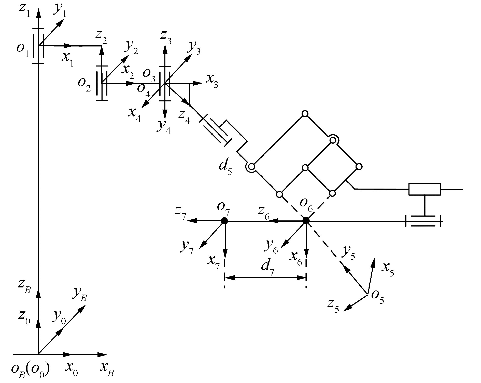
手术机器人由被动关节和主动关节2个分组成,被动关节主要完成术前摆位,对精度要求不高,且运动范围超出位置检测装置测量范围,因此只标定直接影响手术精度的主动关节部分。运动学坐标系如图 7所示,坐标系B为基础坐标系,坐标系0、1、2、3为4个被动关节坐标系,坐标系4、5、6为3个主动关节坐标系,坐标系7为机器人末端工具坐标系。
|
Download:
|
| 图 7 手术机器人运动学坐标系 Fig. 7 Surgical robot kinematics coordinate system | |
已知坐标系i对坐标系i-1相对变换矩阵i-1Ti,
| $ ^{i - 1}{\mathit{\boldsymbol{T}}_i} = \left[ {\begin{array}{*{20}{l}} {\cos {\theta _i}}&{ - \sin {\theta _i}\cos {\alpha _i}}&{\sin {\theta _i}\sin {\alpha _i}}&{{a_i}\cos {\theta _i}}\\ {\sin {\theta _i}}&{\cos {\theta _i}\cos {\alpha _i}}&{ - \cos {\theta _i}\sin {\alpha _i}}&{{a_i}\sin {\theta _i}}\\ 0&{\sin {\alpha _i}}&{\cos {\alpha _i}}&{{d_i}}\\ 0&0&0&1 \end{array}} \right] $ |
运动学参数如表 4所示,机器人末端工具坐标系o7相对于坐标系o4的正运动学模型:
| $ ^4{\mathit{\boldsymbol{T}}_7}{ = ^4}{\mathit{\boldsymbol{T}}_5}{ \cdot ^5}{\mathit{\boldsymbol{T}}_5}{ \cdot ^6}{\mathit{\boldsymbol{T}}_7} = \left[ {\begin{array}{*{20}{l}} {{n_x}}&{{o_x}}&{{a_x}}&{{p_x}}\\ {{n_y}}&{{o_y}}&{{a_y}}&{{p_y}}\\ {{n_z}}&{{o_z}}&{{a_z}}&{{p_z}}\\ 0&0&0&1 \end{array}} \right] $ | (5) |
| 表 4 主动关节运动学参数 Table 4 Kinematics parameters of active joints |
本文根据机器人运动学模型建立绝对误差模型和距离误差模型,与机器人末端姿态无关,因此只使用式中的位置坐标px、py和pz。
4.2 绝对误差模型绝对误差模型利用测量值与运动学模型理论值间的差值辨识机器人运动学参数误差的模型。由于手术机器人主动关节有光栅、磁栅传感器,可以准确获得关节运动量,所以不对3个主动关节的运动量进行标定,需要标定的运动学参数为α5、α6、α7、a5、a6、a7、d5、d6和θ7。
设机器人在基础坐标系的测量位置为M(xm, ym, zm),理论位置为T(xt, yt, zt),则得到绝对误差模型,其中Δq表示需标定的参数误差矩阵,Δp表示位置坐标误差矩阵,J表示误差雅克比矩阵:
| $ \Delta \mathit{\boldsymbol{p}} = \mathit{\boldsymbol{J}} \cdot \Delta \mathit{\boldsymbol{q}} $ |
| $ \Delta \mathit{\boldsymbol{q}} = {\left[ {\Delta {\alpha _5}\;\Delta {\alpha _6}\;\Delta {\alpha _7}\;\Delta {a_5}\;\Delta {a_6}\;\Delta {a_7}\;\Delta {d_5}\;\Delta {d_6}\;\Delta {\theta _7}} \right]^T} $ |
| $ \Delta \mathit{\boldsymbol{p}} = {\left[ {{x_m} - {x_t}\;{y_m} - {y_t}\;{z_m} - {z_t}} \right]^T} $ |
| $ J = \left[ {\begin{array}{*{20}{l}} {\frac{{\partial {p_x}}}{{\partial {\alpha _5}}}}&{\frac{{\partial {p_x}}}{{\partial {\alpha _6}}}}&{\frac{{\partial {p_x}}}{{\partial {\alpha _7}}}}&{\frac{{\partial {p_x}}}{{\partial {a_5}}}}&{\frac{{\partial {p_x}}}{{\partial {a_6}}}}&{\frac{{\partial {p_x}}}{{\partial {a_7}}}}&{\frac{{\partial {p_x}}}{{\partial {d_5}}}}&{\frac{{\partial {p_x}}}{{\partial {d_6}}}}&{\frac{{\partial {p_x}}}{{\partial {d_7}}}}\\ {\frac{{\partial {p_y}}}{{\partial {\alpha _5}}}}&{\frac{{\partial {p_y}}}{{\partial {\alpha _6}}}}&{\frac{{\partial {p_y}}}{{\partial {\alpha _7}}}}&{\frac{{\partial {p_y}}}{{\partial {a_5}}}}&{\frac{{\partial {p_y}}}{{\partial {a_6}}}}&{\frac{{\partial {p_y}}}{{\partial {a_7}}}}&{\frac{{\partial {p_y}}}{{\partial {d_5}}}}&{\frac{{\partial {p_y}}}{{\partial {d_6}}}}&{\frac{{\partial {p_y}}}{{\partial {d_7}}}}\\ {\frac{{\partial {p_z}}}{{\partial {\alpha _5}}}}&{\frac{{\partial {p_z}}}{{\partial {\alpha _6}}}}&{\frac{{\partial {p_z}}}{{\partial {\alpha _7}}}}&{\frac{{\partial {p_z}}}{{\partial {a_5}}}}&{\frac{{\partial {p_z}}}{{\partial {a_6}}}}&{\frac{{\partial {p_z}}}{{\partial {a_7}}}}&{\frac{{\partial {p_z}}}{{\partial {d_5}}}}&{\frac{{\partial {p_z}}}{{\partial {d_6}}}}&{\frac{{\partial {p_z}}}{{\partial {d_7}}}} \end{array}} \right] $ |
假设运动学参数误差Δq′,Δq′=[-0.0350.0401.511.200.80]T, 建立含假设误差的运动学模型。根据绝对误差模型,辨识得到运动学参数误差Δqα,Δqα=[-0.034 10.041 801.5551.103 81.103 1 0 0.868 90]T,建立标定辨识的运动学模型,取10组θ5、θ6、d7代入该模型求解位置坐标pc,同时代入含假设误差的运动学模型得到位置坐标pa,结果如表 5所示。
| 表 5 含假设误差和标定辨识位置坐标 Table 5 Hypothetical error and calibration identification position coordinate |
根据表 5,x方向平均误差0.078 mm,最大值0.111 mm,最小值0.022 mm;y方向平均误差0.092 mm,最大值0.196 mm,最小值0.028 mm;z方向平均误差0.049 mm,最大值0.052 mm,最小值0.048 mm,验证得到绝对误差模型的正确性。
4.3 距离误差模型距离误差模型利用运动距离测量值与理论值间差值辨识机器人运动学参数误差。设机器人末端测量运动距离为lm(i, i+1),理论运动距离为lt(i, i+1),机器人末端运动距离误差Δl(i, i+1)。结合绝对误差模型,得到手术机器人的距离误差模型[11]:
| $ \Delta l\left( {i,i + 1} \right) = \left[ {{b_x},{b_y},{b_z}} \right] \cdot \left( {{\mathit{\boldsymbol{J}}_{i + 1}} - {\mathit{\boldsymbol{J}}_i}} \right) \cdot \Delta \mathit{\boldsymbol{q}} $ | (6) |
式中:
| $ \left[ {{b_x},{b_y},{b_z}} \right] = \left[ {\frac{{{x_t}\left( {i + 1} \right) - {x_t}\left( i \right)}}{{{l_t}\left( {i,i + 1} \right)}},\frac{{{y_t}\left( {i + 1} \right) - {y_t}\left( i \right)}}{{{l_t}\left( {i,i + 1} \right)}},\frac{{{z_t}\left( {i + 1} \right) - {z_t}\left( i \right)}}{{{l_t}\left( {i,i + 1} \right)}}} \right] $ |
假设运动学参数误差Δq′,建立含假设误差的运动学模型。根据距离误差模型,辨识得到运动学参数误差Δqβ,Δqβ=[-0.0320.03902.583 22.103 5201.8550]T,建立标定辨识的运动学模型,取10组q5、q6、d7代入该模型求解运动距离Lc,同时代入含假设误差的运动学模型得到运动距离La,二者误差为ΔL,结果如表 6所示。
| 表 6 含假设误差和标定辨识运动距离 Table 6 Hypothetical error and calibration identification moving distance |
根据表 6,标定运动距离平均误差0.083 3 mm,最大值0.227 6 mm,最小值0.018 3 mm,验证得到距离误差模型的正确性。
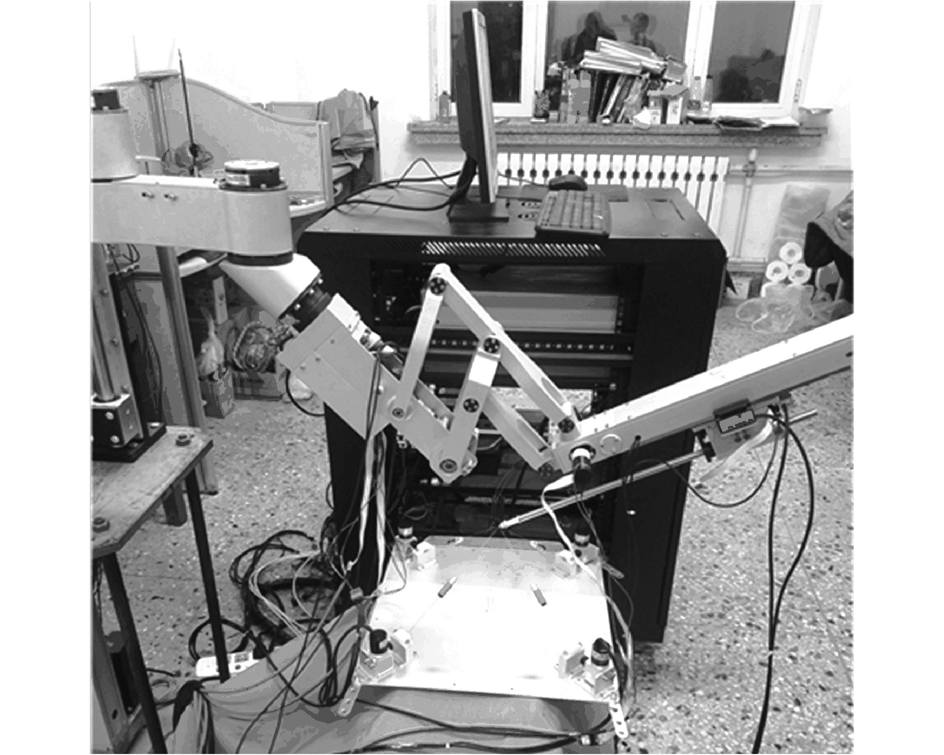
4.4 手术机器人标定实验进行标定实验前,预估机器人末端在实验设定关节变量情况下的大致工作空间,然后布置位置检测装置,使后者测量空间完全包含于前者工作空间,实验平台如图 8所示。
|
Download:
|
| 图 8 手术机器人标定实验平台 Fig. 8 Surgical robot calibration experiment platform | |
选择距离误差模型作为机器人标定的辨识模型,将实验获得20组运动距离代入距离误差模型,使用最小二乘法辨识出各运动学参数误差Δq,再将辨识的参数误差补偿到原运动学模型上,得到实际运动学参数,如表 7所示。
| 表 7 机器人运动学参数辨识结果 Table 7 Robot kinematics parameter identification data |
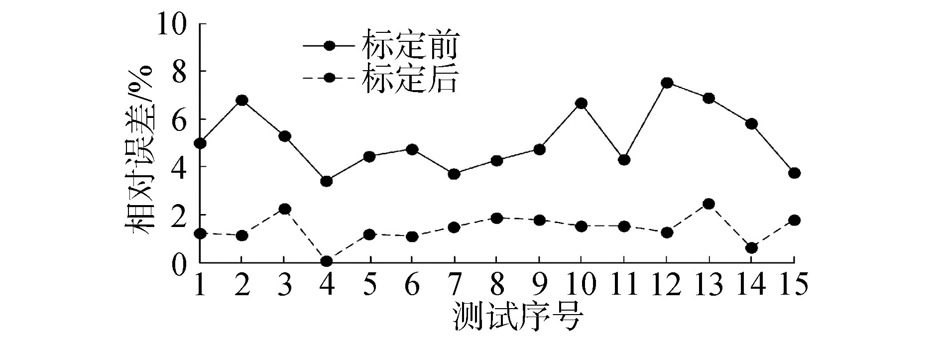
使用位置检测装置对手术机器人运动距离进行测量,并分别使用原模型和修正模型,计算运动距离相对误差,如图 9所示。
|
Download:
|
| 图 9 机器人标定前后运动距离相对误差 Fig. 9 Relative error of distance before and after calibration | |
由图 9可知,手术机器人标定后,运动距离平均相对误差由5.157 9%降低至1.419 6%,精度提高了72%,表明位置检测装置可应用于机器人运动学标定,并为装置应用其他领域提供保证和参考。但是标定后的模型仍有一定误差,分析原因为各关节回程误差和齿轮间隙使机器人存在运动不确定性。
5 结论1) 本文设计一种基于拉线传感器的三维位置检测装置,并提出一种手术机器人运动学标定方法。该方法的优势在于:仅需自制位置检测装置和机器人的角度/位移传感器即可实现运动学标定,无需其他高精度标定设备,成本低且易实现。
2) 建立的自标定误差模型对装置的数学模型进行修正,使得装置测量精度提升61.07%,满足手术机器人标定实验的使用要求。
3) 使用3自由度微创腹腔手术机器人进行标定实验,标定后的平均相对误差下降了72%,实验结果表明本文提出的标定方法与检测装置可以提高手术机器人的定位精度,具有明显的实用价值。
在后续研究中,将使用激光跟踪仪等高精度设备对检测装置的精度做进一步的提高。
| [1] |
ZHANG Hongmin, LI Xiaojian, DING Shuai, et al. A novel dynamic filed tracking algorithm of mirror-holding robot for minimally invasive surgery[C]//Proceedings of 2019 IEEE/ASME International Conference on Advanced Intelligent Mechatronics. Hong Kong, China, 2019.
(  0) 0)
|
| [2] |
张旭, 郑泽龙, 齐勇. 6自由度串联机器人D-H模型参数辨识及标定[J]. 机器人, 2016, 38(3): 360-370. ZHANG Xu, ZHENG Zelong, QI Yong. Parameter identification and calibration of D-H Model for 6-DOF serial robots[J]. Robot, 2016, 38(3): 360-370. (  0) 0)
|
| [3] |
LI Guozhi, ZHANG Fuhai, FU Yili, et al. Kinematic calibration of serial robot using dual quaternions[J]. Industrial robot, 2019, 46(2): 247-258. DOI:10.1108/IR-10-2018-0221 (  0) 0)
|
| [4] |
FURUTANI R, OZAKI M. Uncertainty of calibration of 2D planar coordinate measuring machine[J]. Measurement, 2012, 45(3): 427-430. (  0) 0)
|
| [5] |
张立杰, 李永泉, 王艮川. 基于三坐标测量机的球面5R并联机构运动学标定研究[J]. 中国机械工程, 2013, 24(22): 2997-3002. ZHANG Lijie, LI Yongquan, WANG Genchuan. Research on kinematic calibration of spherical 5R parallel manipulator based on coordinate measuring machine[J]. China mechanical engineering, 2013, 24(22): 2997-3002. (  0) 0)
|
| [6] |
NUBIOLA A, BONEV I A. Absolute robot calibration with a single telescoping ballbar[J]. Precision engineering, 2014, 38(3): 472-480. DOI:10.1016/j.precisioneng.2014.01.001 (  0) 0)
|
| [7] |
QI Fei, PING Xueliang, LIU Jie, et al. The parameter identification and error compensation of robot based on dynacal system[J]. Applied mechanics and materials, 2014, 701-702: 788-792. DOI:10.4028/www.scientific.net/AMM.701-702.788 (  0) 0)
|
| [8] |
FILION A, JOUBAIR A, TAHAN A S, et al. Robot calibration using a portable photogrammetry system[J]. Robotics and computer-integrated manufacturing, 2018, 49: 77-87. DOI:10.1016/j.rcim.2017.05.004 (  0) 0)
|
| [9] |
HAYAT A A, BOBY R A, SAHA S K, et al. A geometric approach for kinematic identification of an industrial robot using a monocular camera[J]. Robotics and computer-integrated manufacturing, 2019, 57: 329-346. DOI:10.1016/j.rcim.2018.11.008 (  0) 0)
|
| [10] |
LUO Ren, WANG Hao. Automated tool coordinate calibration system of an industrial robot[C]//Proceedings of 2018 IEEE/RSJ International Conference on Intelligent Robots and Systems. Madrid, 2018: 5592-5597.
(  0) 0)
|
| [11] |
周学才, 张启先, 郑时雄. 一种新的机器人机构距离误差模型及补偿算法[J]. 机器人, 1991, 13(1): 44-49. ZHOU Xuecai, ZHANG Qixian, ZHENG Shixiong. A new model with compensation algorithm for distance errors of robot mechanisms[J]. Robot, 1991, 13(1): 44-49. (  0) 0)
|
 2020, Vol. 41


