十字头滑块-导板与活塞裙-缸套是船用低速二冲程柴油发动机(以下简称船用低速机)中重要的2对摩擦副。十字头滑块承受着发动机巨大的侧推力,摩擦功耗占整机摩擦损失的一大部分。此外,十字头滑块和活塞的动力学特性也对发动机的振动、噪声和稳定性有重要影响,然而,以往针对船用低速机中这2对摩擦副的研究十分有限,且忽略了对摩擦动力学特性有重要影响的润滑剂粘温特性。因此,精确考虑润滑剂的粘温特性,获得准确的理论模型对这2对摩擦副进行深入全面的研究,对减小发动机摩擦,优化发动机设计是很有必要的。
十字头滑块与活塞裙的摩擦动力学行为相似,二者均是受纵向往复运动和横向二阶运动的综合影响。目前,对活塞裙的数值仿真研究工作主要集中在小型高速四冲程发动机上。Qasim等[1]考虑了润滑油的非牛顿效应,对活塞裙的摩擦学与动力特性做了研究;Meng等[2-3]考虑了连杆等构件惯性的影响,提出了一个更精确的可用于高速四冲程发动机活塞裙-缸套系统的分析模型;Gunelsu等[4]研究了活塞设计参数对该系统的摩擦动力特性影响;孙军等[5]考虑了活塞裙部的润滑油输送状况,讨论了贫油情况下活塞裙的润滑性能;宁李谱等[6]讨论了曲轴销偏置对活塞裙摩擦学性能的影响;吕延军等[7]则重点讨论了活塞轮廓参数的影响。然而,针对船用低速机十字头滑块和活塞裙的研究却十分有限。Abanteriba等[8-10]在忽略十字头滑块-导板和活塞裙-缸套的耦合作用情况下,研究了十字头滑块的摩擦学行为。作者在之前的研究中[11],考虑了十字头滑块、十字头销、活塞杆、活塞的动力学耦合特性,建立了一个新的十字头滑块-导板系统和活塞裙-缸套系统的耦合摩擦动力学模型。本文将在此模型的基础上,考虑润滑油的粘温效应,分析2对摩擦副在工作温度(热态)下的性能,并与冷态情况下的摩擦学与动力学特性进行对比。
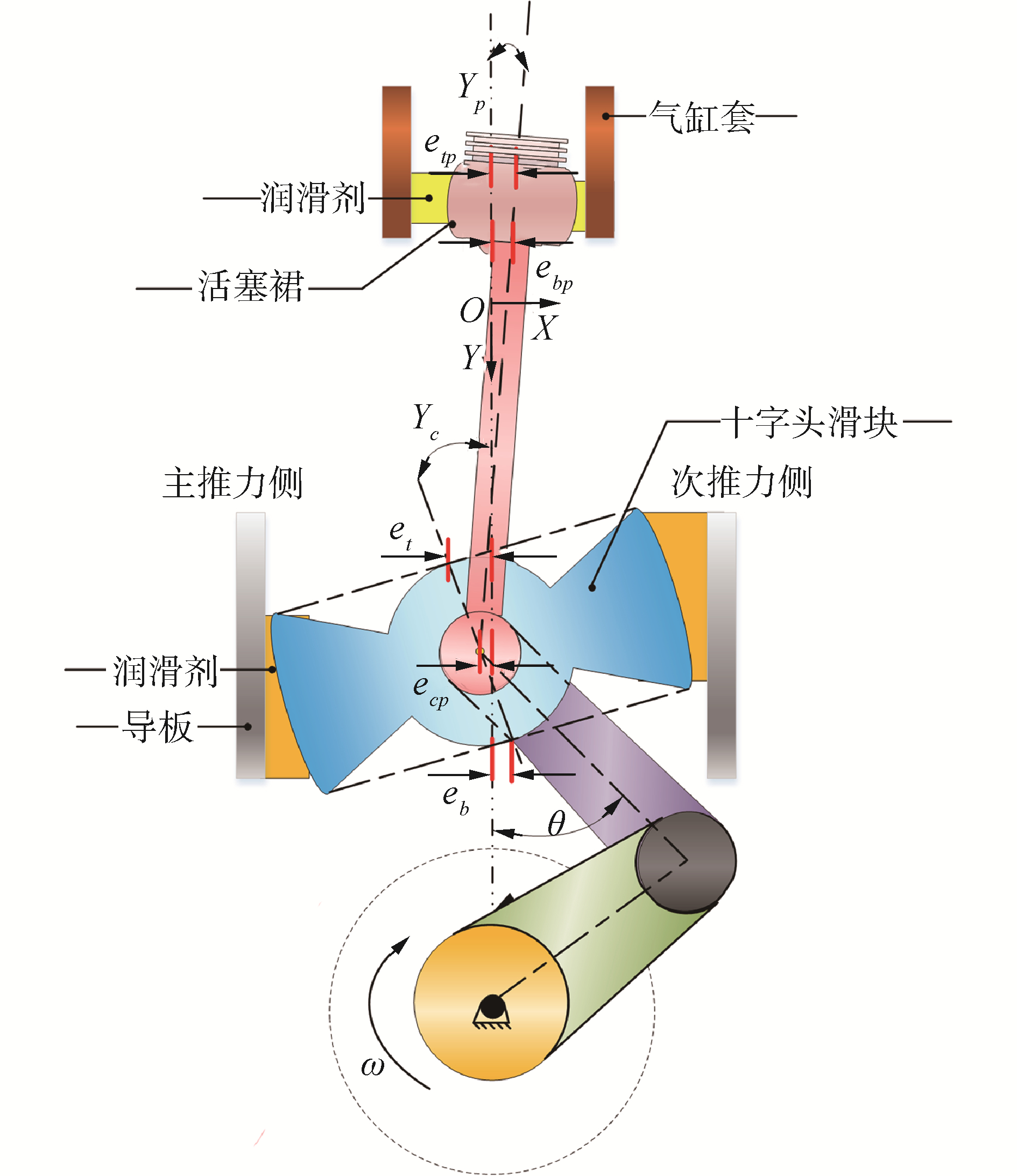
1 船用低速机摩擦动力学模型本文所研究的十字头滑块与活塞除了在纵向做往复直线运动外,还会在横向产生微小位移并伴随着偏摆(如图 1所示),称为二阶运动。图 1中,滑块在各种力的作用下,将会产生横向位移和偏摆,其运动状态用et、eb表示,分别表示滑块上端和下端中点到导板中心线的距离。十字头销一方面通过螺栓与活塞杆相连,活塞杆又与活塞通过螺栓连接为一个整体。十字头销另一方面又与滑块以转动副相连,当忽略十字头销与滑块之间的间隙时,可以认为十字头销-活塞杆-活塞系统在十字头销中心处与滑块在该点的横向位移一致,用ecp表示。但十字头销-活塞杆-活塞系统的摆角与滑块可能不相同,二者转角分别用γc与γp表示。活塞裙的二阶运动可用etp和ebp表示,分别代表活塞裙上下端中点到气缸中心线的距离。滑块和活塞的上述动力学行为将对二者的摩擦学行为产生很大影响。

|
Download:
|
| 图 1 船用低速机结构及运动说明 Fig. 1 Structure and motion description of low-speed marine diesel engine | |
图 2为船用低速机受力分析,对活塞、活塞杆、十字头销和十字头滑块做受力分析,分别列其力及转矩平衡方程,经过整理可以得到3个独立的二阶常微分方程,具体的方程及处理办法可以参考文献[11],在此不再赘述。

|
Download:
|
| 图 2 船用低速机受力分析 Fig. 2 Force analysis of low-speed marine diesel engine | |
3个独立的二阶常微分方程即为耦合了十字头滑块和活塞裙的摩擦动力学模型,可写为:
| $ \left[ {\begin{array}{*{20}{l}} {{A_{11}}}&{{A_{12}}}&{{A_{13}}}\\ {{A_{21}}}&{{A_{22}}}&{{A_{23}}}\\ {{A_{31}}}&{{A_{32}}}&{{A_{33}}} \end{array}} \right]\left[ {\begin{array}{*{20}{c}} {{{\ddot e}_t}}\\ {{{\ddot e}_b}}\\ {{{\ddot e}_{tp}}} \end{array}} \right] = \left[ {\begin{array}{*{20}{c}} {{B_F}}\\ {{B_S}}\\ {{B_T}} \end{array}} \right] $ | (1) |
式中:
| $ \begin{array}{*{20}{c}} {{A_{11}} = - {m_p}\left( {1 - \frac{a}{{{L_3}}}} \right)\left( {1 - \frac{{L + {R_{{\rm{pin}}}} + {L_2}}}{{{L_1} + {L_2} + L + {R_{{\rm{pin}}}}}}} \right) - }\\ {{m_{{\rm{rod}}}}\left( {1 - \frac{a}{{{L_3}}}} \right)\left( {1 - \frac{{\frac{L}{2} + {R_{{\rm{pin}}}}}}{{{L_1} + {L_2} + L + {R_{{\rm{pin}}}}}}} \right)}\\ {{m_{cp}}\left( {1 - \frac{a}{{{L_3}}}} \right) - 2{m_c}\left( {1 - \frac{b}{{{L_3}}}} \right)} \end{array} $ |
| $ \begin{array}{*{20}{c}} {{A_{12}} = - {m_p}\frac{a}{{{L_3}}}\left( {1 - \frac{{L + {R_{{\rm{pin}}}} + {L_2}}}{{{L_1} + {L_2} + L + {R_{{\rm{pin}}}}}}} \right) - {m_{{\rm{rod}}}}\frac{a}{{{L_3}}} \cdot }\\ {\left( {1 - \frac{{\frac{L}{2} + {R_{{\rm{pin }}}}}}{{{L_1} + {L_2} + L + {R_{{\rm{pin }}}}}}} \right) - {m_{cp}}\frac{a}{{{L_3}}} - 2{m_c}\frac{b}{{{L_3}}}} \end{array} $ |
| $ \begin{array}{*{20}{c}} {{A_{13}} = - {m_p}\frac{{L + {R_{{\rm{pin}}}} + {L_2}}}{{{L_1} + {L_2} + L + {R_{{\rm{pin}}}}}} - }\\ {{m_{{\rm{rod}}}}\frac{{\frac{L}{2} + {R_{{\rm{pin}}}}}}{{{L_1} + {L_2} + L + {R_{{\rm{pin}}}}}}} \end{array} $ |
| $ {A_{21}} = - {m_c}\left( {1 - \frac{b}{{{L_3}}}} \right)(a - b) - \frac{{{I_c}}}{{{L_3}}} $ |
| $ {A_{22}} = - {m_c}\frac{b}{{{L_3}}}(a - b) + \frac{{{I_c}}}{{{L_3}}} $ |
| $ {A_{23}} = 0 $ |
| $ \begin{array}{*{20}{c}} {{A_{31}} = - {m_p}\left( {1 - \frac{a}{{{L_3}}}} \right)\left( {1 - \frac{{L + {R_{{\rm{pin}}}} + {L_2}}}{{{L_1} + {L_2} + L + {R_{{\rm{pin}}}}}}} \right) \cdot }\\ {\left( {{L_2} + L + {R_{{\rm{pin}}}}} \right) - {m_{{\rm{rod}}}}\left( {1 - \frac{a}{{{L_3}}}} \right) \cdot }\\ {\left( {1 - \frac{{\frac{L}{2} + {R_{{\rm{pin }}}}}}{{{L_1} + {L_2} + L + {R_{{\rm{pin}}}}}}} \right)\left( {\frac{L}{2} + {R_{{\rm{pin}}}}} \right) + }\\ {\frac{{{I_q}\left( {1 - \frac{a}{{L3}}} \right)}}{{{L_1} + {L_2} + L + {R_{{\rm{pin}}}}}}} \end{array} $ |
| $ \begin{array}{*{20}{c}} {{A_{32}} = - {m_p}\frac{a}{{{L_3}}}\left( {1 - \frac{{L + {R_{{\rm{pin}}}} + {L_2}}}{{{L_1} + {L_2} + L + {R_{{\rm{pin}}}}}}} \right) \cdot }\\ {\left( {{L_2} + L + {R_{{\rm{pin}}}}} \right) - {m_{{\rm{rod}}}}\frac{a}{{{L_3}}}}\\ {\left( {1 - \frac{{\frac{L}{2} + {R_{{\rm{pin}}}}}}{{{L_1} + {L_2} + L + {R_{{\rm{pin}}}}}}} \right)\left( {\frac{L}{2} + {R_{{\rm{pin}}}}} \right) + }\\ {\frac{{{I_q}\frac{a}{{{L_3}}}}}{{{L_1} + {L_2} + L + {R_{{\rm{pin}}}}}}} \end{array} $ |
| $ \begin{array}{*{20}{c}} {{A_{33}} = - {m_p}\frac{{L + {R_{{\rm{pin}}}} + {L_2}}}{{{L_1} + {L_2} + L + {R_{{\rm{pin}}}}}} \cdot }\\ {\left( {L + {R_{{\rm{pin}}}} + {L_2}} \right) - {m_{{\rm{rod}}}}\frac{{\frac{L}{2} + {R_{{\rm{pin}}}}}}{{{L_1} + {L_2} + L + {R_{{\rm{pin}}}}}} \cdot }\\ {\left( {\frac{L}{2} + {R_{{\rm{pin}}}}} \right) - \frac{{{I_q}}}{{{L_1} + {L_2} + L + {R_{{\rm{pin}}}}}}} \end{array} $ |
| $ {B_F} = F + \tan \theta \left( {2{F_{cf}} + {F_{pf}}} \right) - \left( {2{F_c} + {F_p}} \right) $ |
| $ {B_S} = - {M_c} - {M_{cf}} + {F_{ic1}}{C_g} $ |
| $ {B_T} = - {M_p} - {M_{pf}} $ |
| $ \begin{array}{*{20}{c}} {F = \tan \theta \left( {{F_g} + {F_{ip1}} + {F_{{\rm{irod1}}}} + {F_{icp1}} + 2{F_{ic1}} + } \right.}\\ {\left. {2{m_c}g + {m_q}g} \right)} \end{array} $ |
式中:et和eb分别是十字头滑块上端和下端横向位移;etp是活塞裙上端横向位移;mp、mrod、mcp和mc分别是活塞、活塞杆、十字头销、十字头滑块的质量;L、L1、L2、L3分别是活塞杆的长度,活塞质心到活塞裙上端距离,活塞质心到活塞裙下端距离和十字头滑块的长度;a、b分别代表十字头销心,十字头滑块质心到十字头滑块上端距离,Rpin是活塞销半径。Fip1、Firod1、Ficp1、Fic1代表活塞、活塞杆、活塞销、滑块的往复运动惯性力。Fg、mcg、mqg分别代表作用在活塞上的气体力、十字头滑块重力、十字头销、活塞杆和活塞的总重力。Mc、Mcf分别代表作用在十字头滑块上的侧向力和摩擦力对十字头销心的力矩。Mp和Mpf代表作用在活塞裙上的侧向力和摩擦力对十字头销心产生的力矩。
1.2 混合润滑模型考虑了表面粗糙度影响的可用于表示滑块与导板间的流体动压的平均雷诺方程可表示为[12-13]:
| $ \begin{array}{*{20}{c}} {\frac{\partial }{{\partial {x_1}}}\left( {{\phi _x}\frac{{{h^3}}}{{12\eta }}\frac{{\partial p}}{{\partial {x_1}}}} \right) + \frac{\partial }{{\partial {y_1}}}\left( {{\phi _y}\frac{{{h^3}}}{{12\eta }}\frac{{\partial p}}{{\partial {y_1}}}} \right) = }\\ { - \frac{U}{2}\left( {{\phi _c}\frac{{\partial h}}{{\partial {y_1}}} + \sigma \frac{{\partial \left( {{\phi _s}} \right)}}{{\partial {y_1}}}} \right) + {\varphi _c}\frac{{\partial h}}{{\partial t}}} \end{array} $ | (2) |
| $ \tau = - \frac{{\eta U}}{h}\left( {{\phi _f} + {\phi _{fs}}} \right) - {\mathit{\Phi }_{fp}}\frac{h}{2}\frac{{\partial p}}{{\partial {y_1}}} $ | (3) |
式中:p为平均流体动压力;τ为流体剪切力,具体参数意义及计算方法可参见文献[11]。采用Greenwood等[14]提出的粗糙表面微凸体接触模型来确定十字头滑块与导板间的微凸体接触压力,接触压力计算式参考文献[14],在此不再赘述。求解流体动压及接触模型后,对油膜压力和微凸体接触压力进行积分可以求得滑块侧向力;对油膜剪切力和微凸体接触剪切力积分可得到滑块总的摩擦力,具体积分方法可见作者之前工作[11],活塞裙的处理办法与之类似。
1.3 润滑油粘度分析模型对于活塞裙来说,滑油粘度可近似看为活塞裙所处位置处缸套的温度[15]。缸套一点温度可表达为:
| $ {T_0}\left( s \right) = {T_{{\rm{TDC}}}} - \left( {{T_{{\rm{TDC}}}} - {T_{{\rm{BDC}}}}} \right)\sqrt {\frac{\gamma }{S}} $ | (4) |
式中:TTDC是上止点处缸套温度;TBDC是下止点处缸套温度,根据试验数据分别取为270 ℃与110 ℃。y是相对于活塞裙下端位于上止点时的距离,S是活塞冲程。冷态下,缸套温度取为25 ℃。而对于十字头滑块来说,由于曲轴箱温度相对恒定,冷态下取为室温25 ℃,热态下取为80 ℃。十字头滑块使用润滑油为CD40,活塞裙使用的润滑油为CD50。
2 十字头滑块与活塞裙摩擦动力学特性计算结果根据上述理论,针对某型号船用低速机,对比了十字头滑块和活塞裙计入润滑油粘温效应后,在工作温度(热态)和冷态下的摩擦动力学特性。发动机的计算参数见文献[11]。
2.1 冷热态下十字头滑块动力学特性对比图 3比较了十字头滑块在冷热态下的动力学特性。由图 3(a)可以明显看出,当发动机处于热态时,十字头滑块的横向位移幅值相比冷态明显增大。由图 3(b)可知,十字头滑块的横向速度在发火上止点附近明显升高,有使发动机噪声和振动增强的趋势。不难看出,温度升高使十字头滑块的二阶运动更加剧烈,这主要是由于温度的升高使润滑油粘度下降,油膜承载能力下降,而发火上止点后的发动机侧推力的数值却不变,这便要求滑块要产生更大的横向速度,从而依靠更大的挤压效应产生足够大的压力场来承担发动机侧推力。

|
Download:
|
| 图 3 冷热态下十字头滑块动力学特性对比 Fig. 3 Comparisons of the dynamic characteristics of the crosshead slipper under hot state and cold state | |
由图 4(a)可见,在冷态和热态下,十字头滑块侧向力变化不大,这是因为侧向力主要取决于气缸爆发压力和各构件的往复惯性力,受十字头滑块等构件横向运动的影响。由图 4(b)可知,在富油假设下,相比于冷态,热态下十字头滑块的摩擦力明显降低,这是显然的,因为温度的升高使得润滑油粘度降低。

|
Download:
|
| 图 4 冷热态下十字头滑块摩擦学特性对比 Fig. 4 Comparisons of the tribological performance of the crosshead slipper under hot state and cold state | |
图 5显示了十字头滑块在冷态和热态下,主推力侧和次推力侧的最小膜厚。可以看到,在发火上止点后,热态下主推力侧的最小膜厚降低,以在润滑剂粘度减小的情况承担发动机巨大的侧推力。而在发动机的上行冲程中,滑块主推力侧的最小油膜厚度较冷态情况有所上升。与主推力侧的变化相对应,可以看到次推力侧的最小油膜厚度如图 5(b)所示。

|
Download:
|
| 图 5 热态与冷态下十字头滑块最小油膜厚度对比 Fig. 5 Minimum oil film thickness of the crosshead slipper under hot state and cold state | |
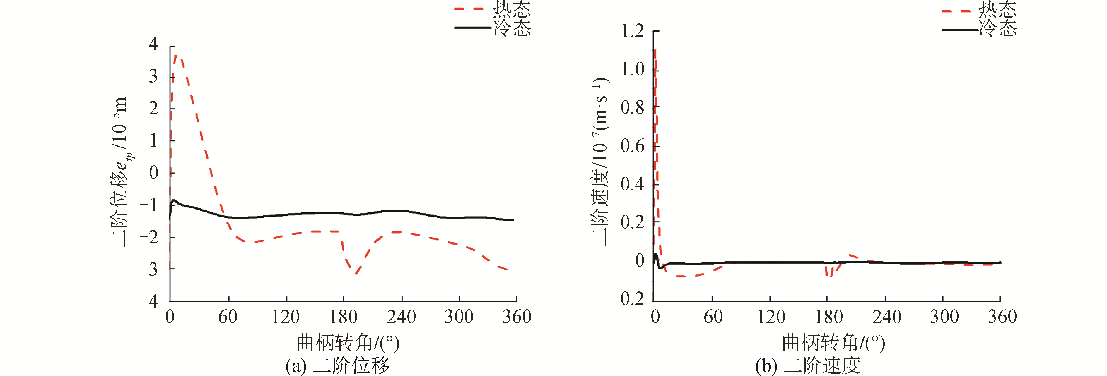
图 6展示了冷热态下活塞裙的动力特性对比。相比于十字头滑块,由于热态下缸套的温度更高,气缸油的粘度更小,所以活塞裙的二阶位移幅值和二阶速度幅值增大更明显。具体来说,如图 6(a)所示,在整个工作循环中,活塞裙的横向位移幅值增大明显。如图 6(b)所示,活塞裙横向运动速度幅值在发火上止点附近也有显著上升。更剧烈的二阶运动会增大发生活塞敲击的可能性。

|
Download:
|
| 图 6 冷热态下活塞裙动力学特性对比 Fig. 6 Comparisons of the dynamic characteristics of the piston skirt under hot state and cold state | |
图 7展示了冷热态下活塞裙的摩擦力对比情况。可以看到,冷热态下活塞裙的摩擦力差别很大,工作温度下活塞裙的摩擦力有大幅度下降。这同样是由于相比冷态,热态下气缸温度的显著升高,润滑油粘度大幅下降。

|
Download:
|
| 图 7 冷热态下活塞裙摩擦力对比 Fig. 7 Comparisons of the friction of the piston skirt under hot state and cold state | |
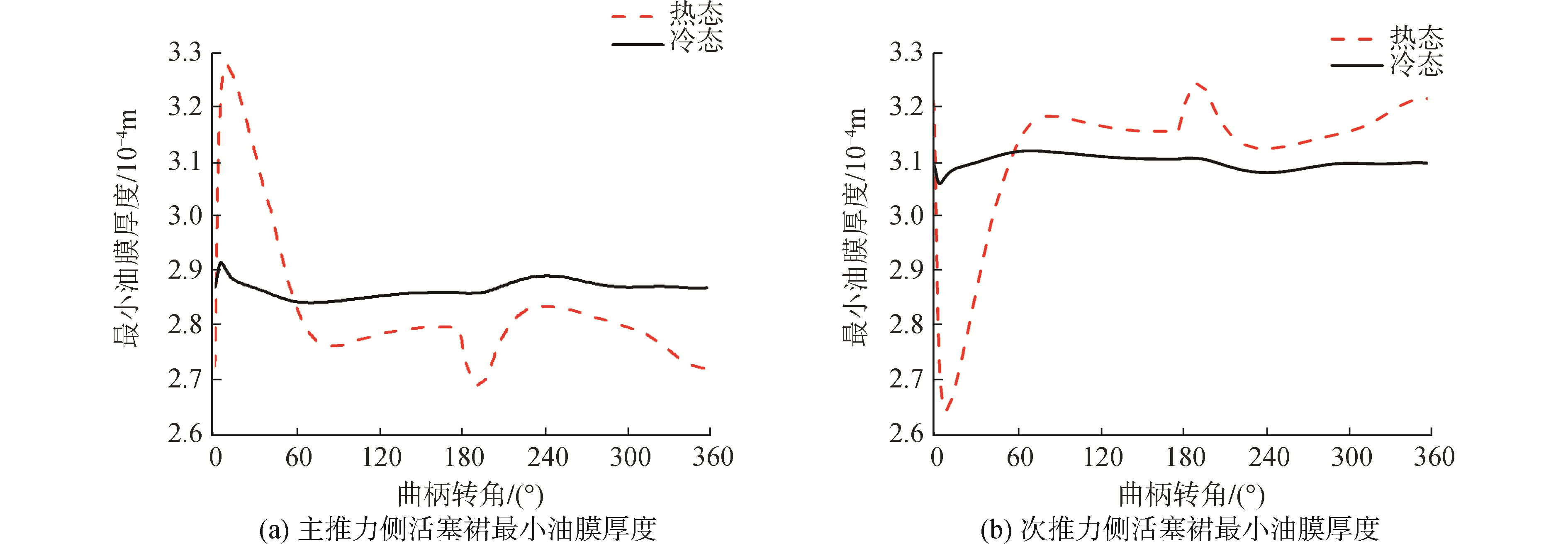
图 8显示了主推力侧和次推力侧活塞裙的最小油膜厚度在一个周期的变化情况。可以看到,发火上止点后,次推力侧活塞裙的最小油膜厚度明显降低,而主推力侧的最小油膜厚度上升,这与其二阶运动的变化有关。

|
Download:
|
| 图 8 热态与冷态下活塞裙最小油膜厚度对比 Fig. 8 Comparisons of the minimum oil film thickness of the piston skirt under hot state and cold state | |
1) 相比冷态,热态下由于润滑剂粘度下降,十字头滑块和活塞裙的摩擦损失均降低。
2) 相比冷态,热态下十字头滑块和活塞裙的二阶运动更加剧烈。在上下止点附近二阶速度升高,且活塞裙升高幅度更大。
3) 相比冷态,热态下由于十字头滑块和活塞裙更剧烈的二阶运动,二者在一个周期内的最小油膜厚度下降。
| [1] |
QASIM S A, CHAUDHRI U F, MALIK M A. Analyzing viscoelastic effects in piston skirts EHL at small radial clearances in initial engine start up[J]. Tribology international, 2012, 45(1): 16-29. (  0) 0)
|
| [2] |
MENG Xianghui, XIE Youbai. A new numerical analysis for piston skirt-liner system lubrication considering the effects of connecting rod inertia[J]. Tribology international, 2012, 47: 235-243. DOI:10.1016/j.triboint.2011.12.013 (  0) 0)
|
| [3] |
MENG Xianghui, FANG Congcong, XIE Youbai. Transient tribodynamic model of piston skirt-liner systems with variable speed effects[J]. Tribology international, 2016, 94: 640-651. DOI:10.1016/j.triboint.2015.10.034 (  0) 0)
|
| [4] |
GUNELSU O, AKALIN O. The effects of piston skirt profiles on secondary motion and friction[J]. Journal of engineering for gas turbines and power, 2014, 136(6): 062503. DOI:10.1115/1.4026486 (  0) 0)
|
| [5] |
孙军, 刘广胜, 苗恩铭, 等. 内燃机活塞裙部-缸套间润滑油输送状况[J]. 机械工程学报, 2016, 52(22): 138-145. SUN Jun, LIU Guangsheng, MIAO Enming, et al. Transport of lubricating oil between piston skirt and cylinder liner for internal combustion engine[J]. Journal of mechanical engineering, 2016, 52(22): 138-145. (  0) 0)
|
| [6] |
宁李谱, 王立新. 曲轴偏置对活塞裙部混合润滑特性的影响[J]. 汽车工程, 2018, 40(5): 597-604. NING Lipu, WANG Lixin. Effects of crankshaft offset on the mixed lubrication characteristics of piston skirt[J]. Automotive engineering, 2018, 40(5): 597-604. (  0) 0)
|
| [7] |
吕延军, 李猛, 张永芳, 等. 轮廓参数对活塞二阶运动和裙部润滑性能的影响研究[J]. 机械工程学报, 2018, 54(15): 100-116. LYU Yanjun, LI Meng, ZHANG Yongfang, et al. Effect of piston skirt profile parameter on secondary motion and lubrication performance of piston[J]. Journal of mechanical engineering, 2018, 54(15): 100-116. (  0) 0)
|
| [8] |
ABANTERIBA S. The analysis of the lubrication condition and friction losses of a single acting cross head guide shoe of a low speed cross head diesel engine:Part I-An alogrithm for the prediction of oil film thickness[J]. Tribology transactions, 2000, 43(4): 665-670. DOI:10.1080/10402000008982393 (  0) 0)
|
| [9] |
ABANTERIBA S. The analysis of the lubrication condition and friction losses of a single acting cross head guide shoe of a low speed cross head diesel engine:Part Ⅱ-A practical model for the determination of the oil film thickness[J]. Tribology transactions, 2000, 43(4): 847-851. DOI:10.1080/10402000008982418 (  0) 0)
|
| [10] |
ABANTERIBA S. The analysis of the lubrication condition and friction losses of a single acting cross head guide shoe of a low speed cross head diesel engine:Part Ⅲ-Friction and its minimization[J]. Tribology transactions, 2000, 43(4): 830-836. DOI:10.1080/10402000008982415 (  0) 0)
|
| [11] |
LI Rui, MENG Xianghui, XIE Youbai. A new coupling tribodynamic model of crosshead slipper-guide system and piston skirt-liner system of low-speed marine diesel engines[J]. Tribology international, 2018, 117: 189-205. DOI:10.1016/j.triboint.2017.09.005 (  0) 0)
|
| [12] |
PATIR N, CHENG H S. Application of average flow model to lubrication between rough sliding surfaces[J]. Journal of lubrication technology, 1979, 101(2): 220-229. DOI:10.1115/1.3453329 (  0) 0)
|
| [13] |
WU Chengwei, ZHENG Linqing. An average reynolds equation for partial film lubrication with a contact factor[J]. Journal of tribology, 1989, 111(1): 188-191. DOI:10.1115/1.3261872 (  0) 0)
|
| [14] |
GREENWOOD J A, TRIPP J H. The contact of two nominally flat rough surfaces[J]. Proceedings of the institution of mechanical engineers, 1970, 185(1): 625-633. DOI:10.1243/PIME_PROC_1970_185_069_02 (  0) 0)
|
| [15] |
FANG Congcong, MENG Xianghui, KONG Xiaoli, et al. Transient tribo-dynamics analysis and friction loss evaluation of piston during cold-and warm-start of a SI engine[J]. International journal of mechanical sciences, 2017, 133: 767-787. DOI:10.1016/j.ijmecsci.2017.09.043 (  0) 0)
|
 2019, Vol. 40


