 2025, Vol. 36


In recent years, due to the global environmental pollution caused by fossil fuels and the increasingly serious situation of energy crisis, clean energy such as solar, wind, and tidal energy have been increasingly researched and utilized. Energy storage technology, like lithium ion batteries (LIBs) is gradually playing an important role in overcoming the limitation of clean energy in terms of time and space. However, with the increasing needs of social development, the batteries’ energy density is facing an urgent breakthrough challenge. Lithium sulfur batteries (LSBs) are considered a promising candidate for next-generation battery technology due to its high mass energy density (2600 Wh/kg), high theoretical specific capacity (1675 mAh/g), and low cost [1–4].
LSBs is a type of lithium ion batteries that use sulfur as the cathode and Li metal as the anode, the conversion between the chemical and electrical energy of LSBs is achieved through the breaking and formation of S-S chemical bonds. The discharging/charging reaction involves a complex and multi-step phase transition processes [5–7]. In the discharge process, the solid S8 undergoes a multi-step reaction in its reduction:
| $ \mathrm{S}_8+2 \mathrm{e}^{-} \rightarrow \mathrm{S}_8^{2-} $ | (1) |
| $ 3 \mathrm{S}_8{ }^{2-}+2 \mathrm{e}^{-} \rightarrow 4 \mathrm{S}_6{ }^{2-} $ | (2) |
| $ 2 \mathrm{S}_6{ }^{2-}+2 \mathrm{e}^{-} \rightarrow 3 \mathrm{S}_4{ }^{2-} $ | (3) |
| $ 3 \mathrm{S}_4^{2-}+4 \mathrm{Li}^{+}+2 \mathrm{e}^{-} \rightarrow 2 \mathrm{Li}_2 \mathrm{S}_2 $ | (4) |
| $ 2 \mathrm{Li}_2 \mathrm{S}_2+2 \mathrm{Li}^{+}+2 \mathrm{e}^{-} \rightarrow 2 \mathrm{Li}_2 \mathrm{S} $ | (5) |
During the discharge process, the long-chain polysulfides like Li2S8 and Li2S6, which are easily soluble in organic electrolytes, are gradually reduced to the short-chain polysulfide compounds like Li2S2 and Li2S, which are insoluble in electrolytes [8,9].
Due to the shuttling effect, the soluble polysulfides will move through the separator and undergoes a reduction reaction with Li metal, which form short polysulfides on the surface of Li anode, it will greatly reduce the Coulomb efficiency (CE) and cycling life of LSBs- [10–12]. In addition, several other challenges such as (1) the low conductivity of the active materials (S) and the final reaction product (Li2S) seriously reduced the electrochemical reactivity, (2) an 80% volume strain during cycling will cause a rapid decline of cycle life, (3) the uneven deposition of Li+ on the anode surface can lead to the formation of “dead lithium” and Li dendrites, causing a negative impact on the electrochemical and safety performance of batteries. In order to solve the above problems and realize high performance lithium sulfur batteries, researchers have carried out a lot of research works involves cathode material coating, electrode structure design, new electrolyte additives and functional separators [13–16].
Separator, as an essential component of batteries, is block between the cathode and anode to prevent the short circuit, so the separator needs to possess some necessary properties, such as: (1) Appropriate porosity to facilitate the smooth move of Li+ and inhibit the shuttling effect of polysulfides; (2) better mechanical properties; (3) stable chemical properties to prevent corrosion and damage during chemical reactions; and (4) good electrolyte wettability to reduce the internal resistance and improve the electrochemical performance [6,17,18]. Therefore, in order to obtain an excellent performance LSBs, a multi-functional separator is particularly important.
Metal organic frameworks (MOFs), also known as porous coordination polymers (PCPs) or porous coordination network compounds (PCNs), are crystalline materials which formed by the coordination interaction of metal ions/clusters with organic ligands. Since 1995, over 30,000 MOFs have been reported, including MOF, UiO, ZIF, IRMOF, MIL, NU, HKUST, MET, and other series [19–23]. Except the traditional solvothermal synthesis methods, some other synthesis methods such as microwave, ultrasonic, liquid phase diffusion, solid-phase, hot-pressing methods are gradually become a common technology to synthesize MOFs [24–27]. These MOFs are widely used in various application areas due to their unique properties, such as adjustable pore size and high specific surface area. It has become an emerging research direction in the interdisciplinary fields of materials and chemistry in the 21st century.
The abundant and adjustable pore structure of MOFs provides an ideal platform for Li+ transport and inhibit the polysulfide shuttling effect. However, powder MOF materials are need to process and mold as a flexible separator for LSBs [28,29]. Therefore, researchers try to develop various manufacturing processing technologies (MPTs) to obtain a flexible MOF-based separators in recent years.
The electrochemical performance of the LSB is greatly affected by the separators’ manufacturing processing technology. In this mini review, we summarize the recent research on the application of MOF-based separators in lithium sulfur batteries. It discusses the effects of MOF-based separator obtained from different MPT on the battery's performance separately, and explore the mechanisms of the separator for high performance LSBs, such as the pore structure of MOFs, stacking density of separator, the wettability of electrolyte, and some other factors. This mini review aims to provide a guidance effect to effectively manufacture the functional MOF-based separator, and promoting the commercialization of lithium sulfur batteries.
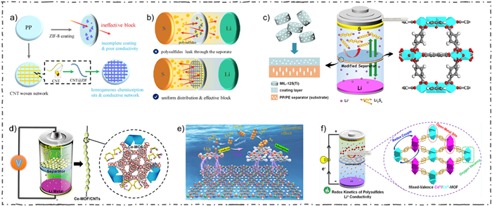
2. MPTs of MOF-based separators 2.1. Doctor-blade method 2.1.1. Lewis acid-base interactionIn 2018, Wu et al. prepared a CNT@ZIF composite slurry by mixing CNT@ZIF-8 with polyvinylidene difluoride (PVDF) and N-methyl-2-pyrrolidone (NMP), then coating the slurry on one side of Celgard 2500 through the doctor blade method to create a CNT@ZIF-coated separator [30]. By utilizing the adsorption and physical barrier effects of CNT and the strong Lewis acid-base interaction between ZIF-8 with polysulfides, the polysulfides can be well confined to the cathode region. It achieved a high initial discharge capacity of 1588 mAh/g at 0.2 C (Figs. 1a and b).

|
Download:
|
| Fig. 1. Schematic of (a) ZIF-8, the CNT@ZIF-8 composites modified separators and (b) their assembled batteries. Reprinted with permission [30]. Copyright 2018, Elsevier Inc. (c) Schematic of the battery with MIL-125(Ti)-modified separator. Reprinted with permission [31]. Copyright 2020, American Chemical Society. (d) Illustration of Co-MOF/CNTs composite separators to catalysis the polysulfides. Reprinted with permission [33]. Copyright 2019, American Chemical Society. (e) Schematic of separator for Li–S battery. Reprinted with permission [34]. Copyright 2023, Elsevier Inc. (f) Schematic of the CSUST-1/CNT composite separator for high performance LSBs. Reprinted with permission [35]. Copyright 2021, American Chemical Society. | |
Qi et al. prepared a MOF-based separator coated with MIL-125 (Ti) that exhibit a good electrolyte wettability [31]. The Lewis acid-base interaction between the O atoms in the MIL-125 ligand and the polysulfides, and the physical/chemical shielding effect of the MOF pores (with a small pore size of 1.5 nm), helped to guide the transport and deposition of Li+ for dendrite-free Li anode, as well as suppressing the shuttling effect of the polysulfides (Fig. 1c). The battery that utilized the MIL-125 composite separator demonstrated an initial discharge capacity of 1218.3 mAh/g at 0.2 C, and the capacity retention rate was over 60% after 200 cycles. Suriyakumar et al. proposed that the COO– anions on the surface of Mn-BTC can create an electrostatic repulsive force with polysulfides [32], which effectively blocked the polysulfides shuttling and improved the battery cycle performance.
Except shielding effect of the anions, the interaction effect of cations also plays an important role in inhibiting polysulfides shuttling. Hong et al. homogeneously mixed Ce-MOF with CNT in isopropanol solution, and then coated it on the Celgard 2400 separator with a mass loading of 0.4 mg/cm2 [33]. Due to the large specific surface area of Ce-MOF-808 and the coordination-unsaturated Ce(Ⅳ)-cluster nodes, the functional separator can quickly adsorb the soluble polysulfides and catalyze it conversion, effectively reducing the shuttling effect (Fig. 1d). Furthermore, the high conductivity of CNTs also enhanced the electrochemical performance and capacity retention of batteries. It exhibited an initial discharge capacity of 993.5 mAh/g at 0.1 C. The capacity can even be maintained about 886.4 mAh/g at high sulfur loading of 6 mg/cm2. Leng et al. incorporated the bimetallic Ni-Co MOF into PAN separators to produce functionalized separators that exhibit high thermal stability and good electrolyte wettability [34]. According to the results of density functional theory (DFT) calculations, the bimetallic MOF modified separator exhibited strong interaction and excellent anchoring effect with polysulfides (Fig. 1e). Additionally, the Gibbs free energy of each chemical reaction step is significantly reduced, indicating that the bimetallic MOF has a significant catalytic effect on polysulfide reduction.
A mixed-valence Ce-MOF (Ⅳ, Ⅲ) with various open metal sites and abundant oxygen vacancies (OVs), named CSUST-1 was synthesized by Jin et al., they mixed the MOF with some other materials like CNT to create a mixed slurry [35]. The slurry was then scrape-coated on the Celgard separator and dried to produce a functional separator with a mass loading of 0.3 mg/cm2. It has been proved that the OVs can act as efficient active sites for multi-phase polysulfides catalysis in Qi's work, combined with the synergistic effect of pore structure of the CSUST-1 and the strong interaction of polysulfides and isolated mixed-valence Ce chains, the soluble polysulfides can be easily adsorbed and quickly catalytically converted (Fig. 1f). The LSBs, with the CSUST-1coated separator, displayed an initial discharge capacity of 1468 mAh/g at 0.1 C, and maintained a long-term stability for a capacity of 538 mAh/g after 1200 cycles at 2 C.
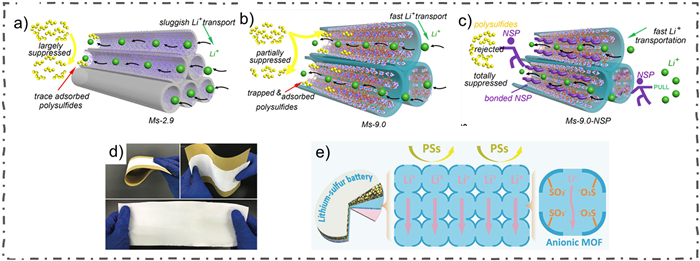
2.1.2. Pore sizeChang et al. continued to investigate the impact of MOFs pore size on the polysulfides shuttling and Li+ transport kinetics under the basis of previous research [36]. It was founded that reducing the pore size of MOFs can greatly suppress the polysulfides diffusion. However, the kinetics of Li+ transport was also slow down, causing a severe polarization of the batteries, greatly inducing the Coulombic efficiency and cycling stability (Figs. 2a-c). It was also founded that the interaction between the polysulfides and the metal sites (metal-Sx2- bonds) can anchored various polysulfides in the cathode region. Coincidentally, this interaction also leaded to a serious sulfur loss in the first cycle, resulting a lower capacity release and lower Coulombic efficiency. So, they utilized a small polymer to modify the pore structure of MOFs to eliminates sulfur loss, as well as efficiently enriched the Li+ and enhanced its transport speed, resulting an excellent battery performance.

|
Download:
|
| Fig. 2. Schematic mechanism of the effection of (a) Ms-2.9, (b) Ms-9.0 and (c) Ms-9.0-NSP on the diffusion of polysulfides and Li+. Reprinted with permission [36]. Copyright 2020, Elsevier Inc. (d) Photographs of the nano-porous separator. (e) Schematic of the nano-porous separator for inhibiting Li dendrite growth and polysulfide shuttling. Reprinted with permission [37]. Copyright 2020, Wiley-VCH. | |
Wang et al. developed a flexible free-standing MOF-based separators by using anionic UiO-66-SO3Li [37]. The MOFs pore structure was modified by incorporating numerous of sulfonic acid anionic groups (SO3–), which effectively and accurately regulated the Li+ flux and obtained uniform Li+ deposition. The pore structure of UiO-66-SO3Li is formed by connecting Zr6O4(OH)4 clusters and 2,5-dicarboxybenzene sulfonate (BDC-SO3-) with a uniform size of approximately 0.6 nm, the pore size is significantly smaller than the soluble polysulfide (Sn2−, 4 < n ≤ 8). Consequently, these modified pores exhibited an anion electrostatic repulsion and size sieving effect, which overtly inhibit the polysulfide shuttling and accelerate the electrode redox activity (Figs. 2d and e). During the first 100 cycles, the capacity decay rate of LSBs with the MOF-based separator is only 0.26% per cycle, which is just about half of the LSBs with a PP separator (0.47% per cycle).
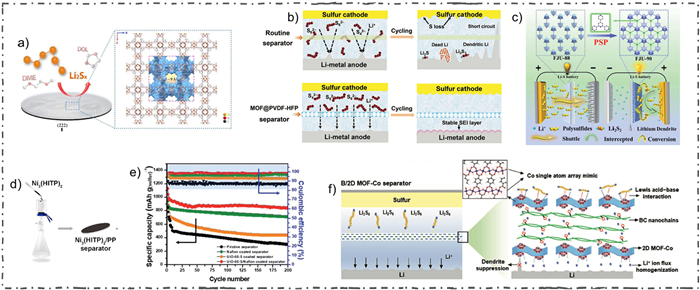
2.2. Filtration method 2.2.1. Pore sizeFiltration method is easier to obtained a free-standing membrane. Bai et al. used a step-by-step approach to filter Zn-HKUST-1 and GO onto a membrane, then peeled off to obtain a free-standing MOF@GO separator after dried [38]. The ionic sieving effect of MOFs was utilized to inhibit the shuttling of polysulfides and protect the Li anode (Fig. 3a). In the electrochemical performance test, the battery exhibited an excellent cycling stability and with a capacity decay rate of only 0.041% per cycle at 1 C within 1000 cycles. He et al. produced a flexible free-standing MOF@PVDF-HFP separator for LSBs by stepwise filtration of HKUST-1 with PVDF-HFP [39]. The narrow pore size (about 9 Å) of the MOF effectively suppressed the diffusion of polysulfides, greatly enhanced the Li+ transport speed, and inhibited the growth of Li dendrites (Fig. 3b). An ultra-low capacity decay rate (0.015% per cycle) over 2000 cycles were achieved as expected.

|
Download:
|
| Fig. 3. (a) Schematic of the Zn-HKUST-1@GO separator. Reprinted with permission [38]. Copyright 2016, Royal Society of Chemistry. (b) Schematic of batteries with a routine separator and an HKUST-1@PVDF-HFP separator. Reprinted with permission [39]. Copyright 2018, Wiley-VCH. (c) Illustration of two different separators (FJU-88 and FJU-90) acting as the ionic sieves for Li+ and the soluble polysulfides. Reprinted with permission [40]. Copyright 2021, Royal Society of Chemistry. (d) Schematic of the separator preparation process by filtration method. Reprinted with permission [41]. Copyright 2019, American Chemical Society. (e) Cycling performances of four kinds of batteries at 0.1 C. Reprinted with permission [42]. Copyright 2018, Royal Society of Chemistry. (f) Schematic of B/2D MOF-Co separator for LSBs. Reprinted with permission [43]. Copyright 2020, Wiley-VCH. | |
Chen et al. modified LSBs separator which using a pore-space-partition strategy for MOFs for the first time, and investigated the effect of the pore structure of MOF-based separator for polysulfides shuttling [40]. A triangular structural ligand tripp was added to the MOFs precursor (FJU-88), the pore channel of FJU-88 was segmented into a uniform connecting pore structure, named FJU-90, and then FJU-88 and FJU-90 was filtered on PP separator to obtain the modified LSBs separator (Fig. 3c). It was found that the FJU-90/PP separator exhibit a smaller pore and more nitrogen sites compared with the FJU-88/PP separator. These pore structures effectively inhibited the shuttling of polysulfides and enhanced the utilization rate of sulfur, as well as a uniform Li deposition behavior. Additionally, the numerous metal cobalt nodes in FJU-90 can catalyze the polysulfides reduction, thus improving the S utilization rate. The capacity retention rate which using the FJU-90/PP separator is about 79.0% for 500 cycles at 1 C, demonstrating an excellent long cycle stability.
2.2.2. Lewis acid-base interactionChen et al. used a simple filtering method to coat the PP separator with the mixture of conductive MOF (Ni3(HITP)2) and PVDF [41]. The porous structure of Ni3(HITP)2 and the various polar sites in the MOFs channel were utilized to reduce the polysulfide shuttling (Fig. 3d). The conductivity of Ni3(HITP)2 also improved the electrochemical reaction kinetics of the batteries. The battery exhibited a high discharge specific capacity of 1220.1 mAh/g at 0.1 C.
Anionic/cationic MOFs exhibited an excellent potential to anchored the polysulfides. Kim et al. obtained a functionalized MOFs separator by mixing sulfonated-UiO-66 with Nafion solution, and then filtered it on the polyethylene (PE) membrane as the separator [42]. The shuttling effect was effectively suppressed by utilizing the sieving effect of MOFs pore and the electrostatic repulsion of polysulfides by sulfonated groups (Fig. 3e). In addition, the sulfonic acid groups are also benefit for enhancing the charge transfer rate. The LSBs with sulfonated-UiO-66-based separator exhibited an initial discharge capacity of 1127.4 mAh/g at 0.1 C, and still maintains about 75.5% after 200 cycles at high current density of 3 C.
Li's team used 2D MOF-Co nanosheets with bacterial cellulose (BC) solution to prepare a flexible bifunctional separator, named B/2D MOF-Co by layer-by-layer filtration (LBL) method [43]. The MOF-Co nanosheets on the anode side are periodically arranged with Co-O4 groups, which makes the Li+ uniform transport and deposited, inhibiting the lithium dendrites growth in anode surface (Fig. 3f). The single Co atom arrays on the cathode side closely anchored the polysulfides through Lewis acid-base interaction effect to reduce the shuttling effect and improve the utilization rate of sulfur. In the long-term cycling stability test, the average capacity decay rate is just 0.07% per cycle at 1 C for 600 cycles. Furthermore, the flexible soft-pack LSBs also showed a stable cycling performance after 200 cycles under different bending conditions, which indicated that the B/2D MOF-Co separator have a certain potential for commercial application.
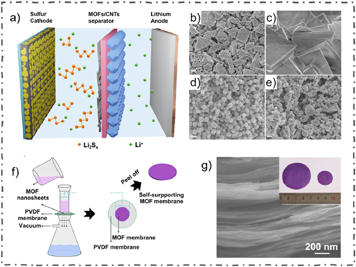
2.2.3. Stacking densityIn 2017, Li et al. aimed to explore the role of MOF's chemical stability and stacking density in inhibiting polysulfide diffusion [44]. They chose four different MOFs to construct separators. It was founded that the chemical stability and stacking density of the MOFs are also critical to the battery performance compared to the pore size of MOFs, which provides an important guidance for the development and utilization of MOF-based separator in the future (Figs. 4a-e).

|
Download:
|
| Fig. 4. (a) Schematic of LSBs with MOF/CNTs modified separator. SEM images of four different MOF-based separators, (b) Y-FTZB, (c) ZIF-7, (d) ZIF-8, and (e) HKUST-1. Reprinted with permission [44]. Copyright 2017, American Chemical Society. (f) Schematic for the preparation process of Cu2(CuTCPP)-based separator. (g) Cross-section SEM image of the Cu2(CuTCPP) separator. Reprinted with permission [45]. Copyright 2019, Elsevier Inc. | |
In 2018, Tian et al. prepared a MOF-based separator with a high orientation degree by filter laminate ultrathin Cu-based MOF nanosheets on PP separator [45]. The dense stacking structure and uniform microporous structure make the MOF-based separator exhibited an excellent physical barrier for polysulfides diffusion, while the oriented pore structure of MOFs also provide a fast path for Li+ transport (Figs. 4f and g). It achieved a high capacity retention rate of 71.1% after cycling for 900 cycles at 1 C.
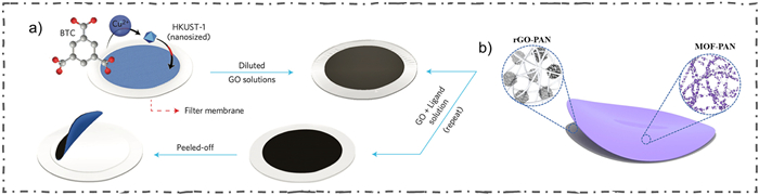
2.3. In situ growth method 2.3.1. Pore sizeGraphene oxide has excellent mechanical properties and it is easily to be prepared on a large scale, exhibiting good potential application as a substrate for MOF-based separator. Bai et al. grew a MOF-199-based composite layer in situ on the surface of a membrane by repeat filtering the MOF-199 precursor solution and diluted graphene oxide (GO) solution [46]. The lamellar GO layer is regularly covered on top of the MOFs layer, and then peeled it off from the filter membrane to obtain MOF@GO separator (Fig. 5a). The prepared separator showed an excellent ion sieving effect and inhibited the shuttling effect. The batteries with the prepared separator achieved an initial discharge capacity of 1126 mAh/g at 0.5 C, and the capacity retention rate is about 71% during 1500 ultra-long cycles at 1 C.

|
Download:
|
| Fig. 5. (a) Schematic of the fabrication process for HKUST-1@GO separators. Reprinted with permission [46]. Copyright 2016, Springer Nature. (b) Schematic of the electrospun MOF-PAN/rGO-PAN separator. Reprinted with permission [47]. Copyright 2020, Elsevier Inc. | |
Zhou's research team used the electrostatic spinning method to prepare a GO-PAN membrane as the MOFs substrate [47]. They mixed the salt solution of MOF precursor with PAN, and then electrospun it on the GO-PAN membrane, then they used the low-pressure chemical vapor deposition method to reintroduce ligands to in situ grow MOFs on the above membrane, a MOF-PAN/rGO-PAN separator was obtained finally (Fig. 5b). The electrospun separator has good electrolyte wettability, liquid absorption as well as rich pore structure. The larger surface area of the separator can provide a large number of polysulfide adsorption sites to inhibit polysulfide shuttling. In addition, the rGO-PAN layer on the anode side can effectively control the rate of Li+ deposition to the anode surface, and reduced the volume strain of the lithium metal anode. In the electrochemical test, the initial capacity can achieve 1302 mAh/g at 0.5 C. In addition, the capacity decay rate was only 0.03% per cycle when cycling 600 cycles at a high current density of 5 C.
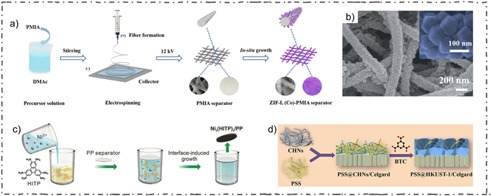
2.3.2. Lewis acid-base interactionLiu et al. immersed the pre-electrospuned PMIA membrane in the precursor solution of ZIF-L(Co), and then the sheet-like ZIF-L(Co) was in situ grown on the membrane (Fig. 6a), called Z-PMIA separator [48]. The separators exhibited an excellent mechanical and thermal stability, with a tensile strength of 15 MPa and a puncture force of 0.95 N. The electrochemical test results indicated that the Z-PMIA separator assembled batteries have a high reversible capacity and stable cyclability due to its high specific surface area and abundant metal active sites. The initial discharge capacity was 1391.2 mAh/g at 0.2 C, and it maintained about 961.1 mAh/g after 350 cycles. However, Liu also found that the PMIA has some drawbacks as a separator substrate, like low electrolyte wettability. So, in their next research, they improved the previous research protocol by adding some high electrolyte wettability PVDF-HFP into the PMIA, called P-PMIA [49]. Then they in situ grew ZIF-8 on it to obtain P-PMIA@ZIF-8 composite separator (Fig. 6b). The upgraded separator also exhibited an excellent high energy density and cycling stability.

|
Download:
|
| Fig. 6. (a) Illustration of the preparation process of the Z-PMIA separator. Reprinted with permission [48]. Copyright 2021, Elsevier Inc. (b) SEM images of the P- PMIA@ZIF-8 separator. Reprinted with permission [49]. Copyright 2022, Royal Society of Chemistry. (c) Schematic illustration of preparation process for the conductive Ni3(HITP)2-based separator. Reprinted with permission [50]. Copyright 2018, Wiley-VCH. (d) Schematic of the preparation process for PSS@HKSUT-1-based separator. Reprinted with permission [51]. Copyright 2018, American Chemical Society. | |
Zang et al. used in situ liquid-solid interface growth method to prepare a composite separator by introducing crack-free and conductive MOF (Ni3(HITP)2) layer on one side of PP separator (Fig. 6c) [50]. It formed a 2D layered structure with hexagonal pores on the ab-crystalline surface. Additionally, a uniform 1D honeycomb pore structure along the c-axis direction under the effect of strong π-π bonding was uniformly formed. The pore of MOFs contains various polar sites, like electronegative N elements, which make it easier to adsorb the polar polysulfides. As a Janus separator, it consisted by a conductive Ni3(HITP)2 side and an insulative PP side. The conductive side can greatly impede the polysulfide shuttling and enhance its electrochemical reaction, greatly improving the sulfur utilization. Meanwhile, the PP layer side can effectively prevent the short circuit of batteries, enabling to realize a high-safety LSBs. It achieved a high initial discharge capacity of 1244 mAh/g when tested at 0.2 C, and a surface capacity of 7.24 mAh/cm2 was maintained after 200 cycles at a high sulfur loading of 8 mg/cm2. This method of preparing MOF composite separators exhibit a good reference for the subsequent development of new functionalized MOF composite separators.
Guo et al. synthesized a MOF composite separator by using domain-limited in situ growth method [51]. Copper hydroxide nanowires (CHN) were used as the metal source, the negatively charged PSS and positively charged CHN were homogeneously mixed firstly, and then filter the mixture on the Celgard 2400 separator, called PSS@CHNs. The PSS@CHNs separators were then immersed into the H3BTC solution, an in situ reaction occurred as a predictable result, called PSS@HKUST-1 separator (Fig. 6d). The three-dimensional PSS network contains a large number of sulfonic acid groups that significantly promote Li+ transport and ensure fast electrochemical reaction kinetics. Additionally, the MOF separator's pore size structure and large number of sulfonic acid groups provide the electrostatic repulsion and ion sieving effects, effectively inhibiting the shuttling of polysulfides. The reversible capacity maintained about 75% after 500 cycles at 0.5 C.
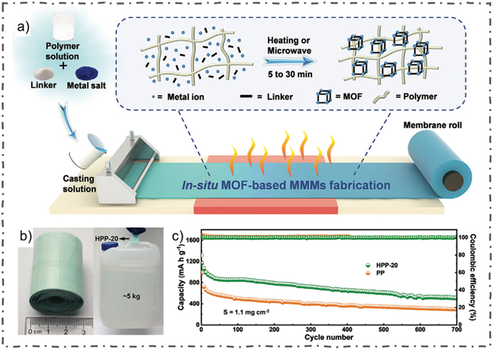
2.3.3. OthersMass production of MOF-based functionalized separators still remains an insurmountable challenge, Gao and his team proposed a in situ heat-assisted solvent-evaporation (HASE) method to produce MOF-based separators in industrial-level efficiency [52]. The separator was fabricated by casting the mixture of MOF (i.e., HKUST-1, UiO-66) precursors with polymers (i.e., PVC, PP, PVDF) in solvent firstly, and meanwhile, through the well-controlled temperature synthesis process, a uniformed and robust separator was obtained finally (Figs. 7a and b). The Li-S batteries with the functionalized separator exhibited an initial discharge capacity of 1163.7 mAh/g and remained about 500 mAh/g after 700 cycles at the current density of 0.5 C (Fig. 7c). This massively fabrication method of MOF-based separator might promote the potential commercialization process of MOF-based separator for the future.

|
Download:
|
| Fig. 7. (a) Schematic of in situ HASE method for fabricating MOF-based separators. (b) Photo images of HPP-20 separator and the tensile stress test. (c) Cycling performance tests of HPP-20 and PP based batteriees at 0.5 C. Reprinted with permission [52]. Copyright 2020, Wiley-VCH. | |
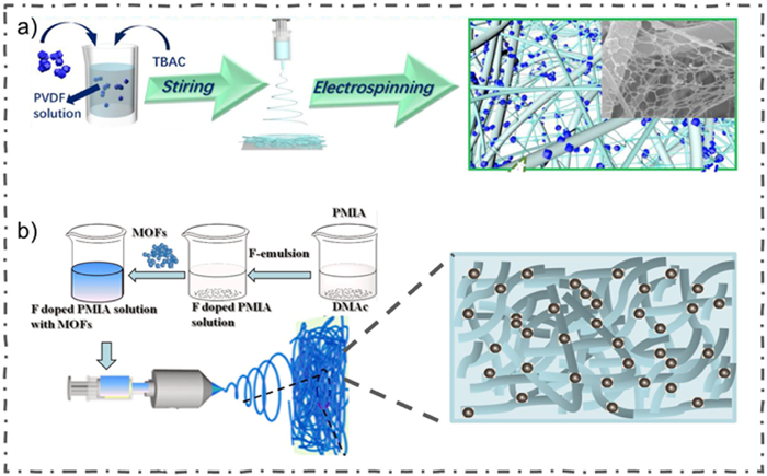
Feng et al. constructed a spiderweb-like ZIF-8@TBAC-PVDF (ZIF@T-PVDF) nanofiber separator by mixing ZIF-8, tetrabutylammonium chloride (TBAC) and PVDF together (Fig. 8a), and then electrostatic spinning this mixture materials [53]. The MOF nanoparticles on the surface of the separator enhanced the adsorption of electrolyte, benefiting for the high speed of Li+ transport, as well as plays a certain rectifying effect of Li+, which greatly alleviated the problem of Li dendrite growth. The spiderweb-like separator also has a physical hindering effect on polysulfides, which is aided by the electrostatic repulsion of F– that hinder the transport of polysulfides.

|
Download:
|
| Fig. 8. (a) Schematic of the preparation process for the ZIF@T-PVDF separator. Reprinted with permission [53]. Copyright 2021, Elsevier Inc. (b) The illustration of the synthesis process for two MOFs (ZIF-67 and HKUST-1)-based PMIA separator. Reprinted with permission [54]. Copyright 2020, Elsevier Inc. | |
In 2020, Deng et al. prepared the F-MOFs-co-doped PMIA nanofiber separator by electrostatic spinning of two different MOFs (Fig. 8b), ZIF-67 and Cu-BTC after homogeneously mixing with F-PMIA [54]. It has relatively high porosity, small pore size and good electrolyte wettability. Additionally, it exhibited excellent thermal stability, mechanical strength and ionic conductivity. Therefore, as a LSBs separator, the polysulfide shuttling and Li dendrite growth can be well inhibited. Due to the synergistic effect of F doping and the MOFs structure, the LSBs with ZIF-67 and Cu-BTC modified separators exhibited a high initial discharge capacities of 1267.5 and 1272.2 mAh/g at 0.5 C, respectively, and after 500 cycles, they maintained a reversible discharge capacity of 698.1 and 752.6 mAh/g, which is significantly higher than the batteries with PMIA separators.
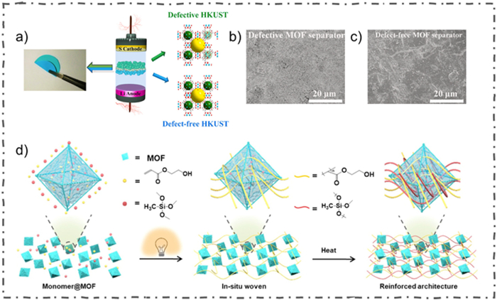
2.5. OthersExcept the methods mentioned above, researchers also have developed some other novel manufacture methods for preparing MOF-based separator, like using the roller pressing method. Wu et al. indicated a defective engineered MOF separator by utilizing roller pressing method, they successfully introduced defective and defect-free HKUST-1 on each side of commercial separator as the defect-engineered MOF separator [55]. The defective side of separators has a positive effect on the catalytic activity, effectively inhibiting the polysulfide shuttling due to the Lewis acid-base interaction. Meanwhile, on the anode region, the defect-free side of separators exhibited a balanced internal electric field and a stable Li+ stripping/plating situation which reduced the possibility of dendrite growth (Figs. 9a-c). During the first 1000 cycles, the LSBs assembled with double-layer MOF separators exhibited an ultra-low capacity decay rate of 0.06% per cycle. This study presents a new approach about the interfacial engineering of separator for high performance LSBs.

|
Download:
|
| Fig. 9. (a) Schematic of defective and defect-free HKUST-1 for bilayer separator. The SEM images of Li metal assembled with the (b) defective MOFs and (c) defect-free MOF separators after cycling. Reprinted with permission [55]. Copyright 2021, Elsevier Inc. (d) Schematic of the PHAP method for MOF-based separator. Reprinted with permission [56]. Copyright 2021, Wiley-VCH. | |
Furthermore, Gao et al. proposed a two-step photo-induced heat-assisted processing (PHAP) method that combined by photo-induced molding and heat-assisted curing [56]. This method is capable of preparing MOFs composites into various devices, such as fibers, hollow tubes and triple-layer separators. In this study, the researcher homogeneously mixed Cetyltrimethyl ammonium bromide (CTAB), urea, photoinitiator 2959, 2-hydroxyethyl acrylate (HEA) and trimethoxy(methyl)silane (MTMS) with activated UiO-66 together and ultrasonic it for thirty minutes. Then added this suspension into a PTFE mold and use a 300 W xenon lamp as the radiant light source. Finally, the materials were heated at 60 ℃ in the oven for about half of the day to obtain the functionalized separator (Fig. 9d). A high initial specific capacity is maintained about 1365.0 mAh/g when applied this separator to LSBs. This method inspires a new exploration direction of manufacturing MOF-based separator for the future.
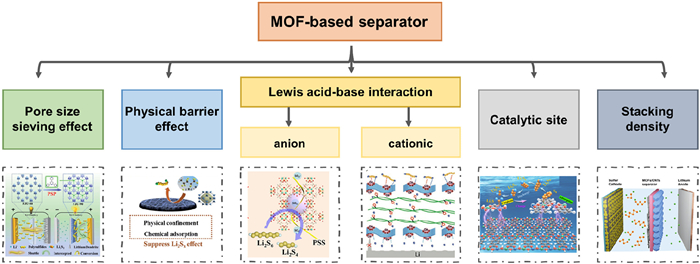
3. Conclusions and perspectivesAs rechargeable batteries, LSBs have been gain unprecedented attention by researchers in recent decades due to its high capacity/energy density, high abundance and low cost, which show promising potential to meet the growing demand for transportation and the grid. However, despite these advantages, there are still some tough challenges for commercialized lithium-sulfur batteries, such as the shuttling effect of soluble polysulfides, uncontrollable Li anode corrosion/dendrite growth and significant volumetric strain. In this review, we systematically summarized the different manufacturing process of MOF-based separator for LSBs over the recent years, and also discussed the mechanism of MOF-based separators for overcoming the above-mentioned challenges and improving the batteries performance in details (Fig. 10).

|
Download:
|
| Fig. 10. The mechanism of MOF-based separators for LSBs mentioned in the review. | |
Numerous MOF-based separator manufacturing methods have been proposed such as doctor-blade method, filtration method, in situ growth method, electrospinning method, roller pressing method and PHAP method. Nevertheless, how to construct a practical potential MOF-based LSBs separator still remain many challenges. These manufacturing methods have all shown effectiveness for high performance LSBs in the lab tests, but meanwhile, the limitations are also very obvious. For example, it is hard to achieve large-scale industrialization of filtration method and in situ growth method due to their high energy consumption required as well as the operational complexity in the batteries field. The electrospinning method lacks the ability to work continuously, and it is also very strict in selection of the electrospinning polymer. The PHAP manufacturing method exhibits high requirements for preparation instruments, seriously increasing the production cost. For doctor-blade method, it's a mature preparation method in the field of battery preparation and equipment. However, the additionally introduced coatings will increase the mass of the separator, which is unfavorable for high mass energy density batteries.
In conclusion, despite these challenges, the separator obtained by these manufacturing methods also shows great application potential for high performance batteries due to the intrinsic characteristics of MOFs, such as high surface area, adjustable pore size and abundant chemical environment inside of MOFs channel. In the future studies, we should take the synergetic advantages of manufacturing methods and MOFs, like in situ rolling press MOFs with reasonable pore size and functional groups on the commercialized separator, achieving a thin and flexible LSBs separator with an excellent inhibit affection of polysulfides shuttling, and realizing a high performance LSBs. It is expected that this mini-review will promote more works which dedicated to develop reliable MOF-based separator manufacturing methods for next-generation lithium sulfur batteries.
Declaration of competing interestThe authors declare that they have no known competing financial interests or personal relationships that could have appeared to influence the work reported in this paper.
CRediT authorship contribution statementXing Gao: Writing – review & editing, Funding acquisition, Conceptualization. Luofeng Wang: Writing – original draft. Jia Cheng: Writing – original draft. Jialiang Zhao: Writing – original draft. Xueli Liu: Writing – review & editing, Visualization, Validation, Conceptualization.
AcknowledgmentsThis work was financially supported by the University Natural Science Research Key Project of Anhui Province (Nos. KJ2021A1091, 2023AH051619), Innovation and Entrepreneurship Training Program for College Students (No. 202310377030) and Scientific Research Start Foundation Project of Chuzhou University (No. 2022qd011).
| [1] |
R. Deng, M. Wang, H. Yu, et al., Energy Environ. Mater. 5 (2022) 777-799. DOI:10.1002/eem2.12257 |
| [2] |
M. Zhao, B.Q. Li, X.Q. Zhang, et al., ACS Cent. Sci. 6 (2020) 1095-1104. DOI:10.1021/acscentsci.0c00449 |
| [3] |
Y. Li, S. Guo, Matter 4 (2021) 1142-1188. |
| [4] |
J. Zhao, Y. Qi, Q. Yang, et al., Chem. Eng. J. 429 (2022) 131997. |
| [5] |
R. Zou, W. Liu, F. Ran, InfoMat 4 (2022) 12319. |
| [6] |
Y.W. Tian, Y.J. Zhang, L. Wu, et al., ACS Appl. Mater. Interfaces 15 (2023) 6877-6887. DOI:10.1021/acsami.2c20461 |
| [7] |
J.G. Kim, Y. Noh, Y. Kim, Chem. Eng. J. 435 (2022) 131339. |
| [8] |
Z.W. Seh, Y. Sun, Q. Zhang, et al., Chem. Soc. Rev. 45 (2016) 5605-5634. |
| [9] |
F. Pei, S. Dai, B. Guo, et al., Energy Environ. Sci. 14 (2021) 975-985. DOI:10.1039/d0ee03005h |
| [10] |
Q. Shao, S. Zhu, J. Chen, Nano Res. 16 (2023) 8097-8138. DOI:10.1007/s12274-022-5227-0 |
| [11] |
S. Li, H. Dai, Y. Li, et al., Energy Storage Mater. 18 (2019) 222-228. |
| [12] |
Z. Li, J. Wu, P. Chen, et al., Chem. Eng. J. 435 (2022) 135125. |
| [13] |
C. Shi, M. Yu, Energy Storage Mater. 57 (2023) 429-459. |
| [14] |
Y. Zhang, C. Guo, J. Zhou, et al., Small 19 (2023) e2206616. |
| [15] |
Z. Han, S. Li, M. Sun, et al., J. Energy Chem. 68 (2022) 752-761. DOI:10.3390/su14020752 |
| [16] |
H. Sul, A. Bhargav, A. Manthiram, Adv. Energy Mater. 12 (2022) 2200680. |
| [17] |
X. Zhang, W. Yuan, H. Huang, et al., Inter. J. Extreme Manufac. 5 (2022) 015501. |
| [18] |
Y. Zhang, C. Guo, L. Zhou, et al., Small Sci. 3 (2023) 2300056. |
| [19] |
S. Foley, H. Geaney, G. Bree, et al., Adv. Funct. Mater. 28 (2018) 1800587. |
| [20] |
P. Marino, P.R. Donnarumma, H.A. Bicalho, et al., ACS Sustain. Chem. Eng. 9 (2021) 16356-16362. DOI:10.1021/acssuschemeng.1c06032 |
| [21] |
C.W. Ashling, D.N. Johnstone, R.N. Widmer, et al., J. Am. Chem. Soc. 141 (2019) 15641-15648. DOI:10.1021/jacs.9b07557 |
| [22] |
D. Sun, M. Xu, Y. Jiang, et al., Small Methods 2 (2018) 1800164. |
| [23] |
S. Hou, W. Ding, S. Liu, et al., Chem. Eng. J. 460 (2023) 141785. |
| [24] |
S. Xie, F. Li, S. Xu, et al., Chin. J. Catal. 40 (2019) 1205-1211. |
| [25] |
K. Ge, S. Sun, Y. Zhao, et al., Angew. Chem. Int. Ed. 60 (2021) 12097-12102. DOI:10.1002/anie.202102632 |
| [26] |
Z. Zhao, H. Li, K. Zhao, et al., Chem. Eng. J. 428 (2022) 131006. |
| [27] |
W. Li, Y. Zhang, Z. Yu, et al., ACS Nano 16 (2022) 14779-14791. DOI:10.1021/acsnano.2c05624 |
| [28] |
Y. Jeon, J. Lee, H. Jo, et al., Chem. Eng. J. 407 (2021) 126967. |
| [29] |
S. Qiu, J. Zhang, X. Liang, et al., Chem. Eng. J. 450 (2022) 138287. |
| [30] |
F. Wu, S. Zhao, L. Chen, et al., Energy Storage Mater. 14 (2018) 383-391. |
| [31] |
C. Qi, L. Xu, J. Wang, et al., ACS Sustain. Chem. Eng. 8 (2020) 12968-12975. DOI:10.1021/acssuschemeng.0c03536 |
| [32] |
S. Suriyakumar, M. Kanagaraj, M. Kathiresan, et al., Electro. Acta 265 (2018) 151-159. |
| [33] |
X.J. Hong, C.L. Song, Y. Yang, et al., ACS Nano 13 (2019) 1923-1931. |
| [34] |
X. Leng, J. Zeng, M. Yang, et al., J. Energy Chem. 82 (2023) 484-496. |
| [35] |
H.G. Jin, M. Wang, J.X. Wen, et al., ACS Appl. Mater. Interfaces 13 (2021) 3899-3910. DOI:10.1021/acsami.0c18899 |
| [36] |
Z. Chang, Y. Qiao, J. Wang, et al., Energy Storage Mater. 25 (2020) 164-171. |
| [37] |
Z. Wang, W. Huang, J. Hua, et al., Small Methods 4 (2020) 2000082. |
| [38] |
S. Bai, K. Zhu, S. Wu, et al., J. Mater. Chem. A 4 (2016) 16812-16817. |
| [39] |
Y. He, Z. Chang, S. Wu, et al., Adv. Energy Mater. 8 (2018) 1802130. |
| [40] |
Y. Chen, L. Zhang, H. Pan, et al., J. Mater. Chem. A 9 (2021) 26929-26938. DOI:10.1039/d1ta07820h |
| [41] |
H. Chen, Y. Xiao, C. Chen, et al., ACS Appl. Mater. Interfaces 11 (2019) 11459-11465. DOI:10.1021/acsami.8b22564 |
| [42] |
S.H. Kim, J.S. Yeon, R. Kim, et al., J. Mater. Chem. A 6 (2018) 24971-24978. DOI:10.1039/c8ta08843h |
| [43] |
Y. Li, S. Lin, D. Wang, et al., Adv. Mater. 32 (2020) 1906722. |
| [44] |
M. Li, Y. Wan, J.K. Huang, et al., ACS Energy Lett. 2 (2017) 2362-2367. DOI:10.1021/acsenergylett.7b00692 |
| [45] |
M. Tian, F. Pei, M. Yao, et al., Energy Storage Mater. 21 (2019) 14-21. |
| [46] |
S. Bai, X. Liu, K. Zhu, et al., Nat. Energy 1 (2016) 16010. |
| [47] |
C. Zhou, Q. He, Z. Li, et al., Chem. Eng. J. 395 (2020) 124979. |
| [48] |
J. Liu, J. Wang, L. Zhu, et al., Chem. Eng. J. 411 (2021) 128540. |
| [49] |
J. Liu, J. Wang, L. Zhu, et al., J. Mater. Chem. A 10 (2022) 14098-14110. DOI:10.1039/d2ta03301a |
| [50] |
Y. Zang, F. Pei, J. Huang, et al., Adv. Energy Mater. 8 (2018) 1802052. |
| [51] |
Y. Guo, M. Sun, H. Liang, et al., ACS Appl. Mater. Interfaces 10 (2018) 30451-30459. DOI:10.1021/acsami.8b11042 |
| [52] |
G. Gao, Y. Wang, H. Zhu, et al., Adv. Sci. 7 (2020) 2002190. |
| [53] |
Y. Feng, G. Wang, W. Kang, et al., Electro. Acta 365 (2021) 137344. |
| [54] |
N. Deng, L. Wang, Y. Feng, et al., Chem. Eng. J. 388 (2020) 124241. |
| [55] |
H. Wu, Y. Yang, W. Jia, et al., J. Alloy. Compd. 874 (2021) 159917. |
| [56] |
G.K. Gao, Y.R. Wang, S.B. Wang, et al., Angew. Chem. Int. Ed. 60 (2021) 10147-10154. DOI:10.1002/anie.202016608 |