 2024, Vol. 35


b School of Chemistry and Chemical Engineering, Shandong University, Ji'nan 250100, China
Lead halide perovskites (LHPs) have shown broad applications in lighting, display, and biological imaging due to their fascinating optical properties and ease of synthesis [1,2]. However, the current study was mainly limited to the visible light region. To expand the application range of LHPs, some rare earth ions (RE3+) singly-doped LPHs with NIR emission have been reported. In this regard, a typical example is that the PLQY of Yb3+ singly-doped CsPbCl3 can over 100% through quantum cutting [3]. Although the initial achievements have been made, the intrinsic toxicity of lead and the poor stability of LHPs severely limit its further application.
Lead-free double perovskites (DPs), with the formula of Cs2AIBIIICl6 (A = Na, K, Ag, Cu; B = In, Bi, Sb), have drawn much attention due to their low toxicity and unique photoelectric properties, and it is considered as an ideal alternative to LPHs [4–6]. However, RE3+ singly-doped DPs generally show the poor NIR emission intensity (e.g., Yb3+ singly-doped Cs2AgInCl6 [7] and Ho3+ singly-doped Cs2KInCl6 [8]), which cannot meet the needs of practical application. To alleviate this, the introduction of metal ion sensitizers into RE3+-doped DPs can effectively boost the emission intensity of RE3+ via the energy transfer (ET) from sensitizers to RE3+. Among various schemes, ns2 metal ions (Sb3+ and Bi3+) and RE3+-codoped DPs have been demonstrated to be a feasible strategy [9–11], as they have the same valence state and similar ion radii. For example, Nag et al. reported Sb3+/Er3+-codoped Cs2NaInCl6, and the emission stems from the 4f-4f transition of Er3+ was greatly enhanced via the ET from STE to Er3+ [12]. Parallelly, the NIR emission of Bi3+/Yb3+-codoped Cs2AgInCl6 is ~27 times higher than that of the Er3+ singly doping [13]. However, the low PLQY of ns2 metal ions and RE3+-codoped DPs is still at a low level, as there is a significant difference in ionic activity between RE3+ and trivalent metal ions (BIII) of DPs, which makes it difficult for RE3+ to enter the host lattice and achieve efficient NIR emission. To overcome the problems, it is important to explore the rare earth-based DPs host matrix to achieve controllable RE3+ doping and efficient NIR emission [14].
Here, we synthesized Sb3+/Sm3+-codoped the carefully selected host matrix of rare earth-based Cs2NaLuCl6 DPs via a typical one-pot hydrothermal method. Upon photoexcitation, the fingerprint emission bands of STE emission and 4f-4f transition of Sm3+ in Sb3+/Sm3+-codoped Cs2NaLuCl6 can be witnessed, and the PLQY in the visible light region and NIR light region can reach up to 74.58% and 23.12%, respectively. The ET mechanism between STE and Sm3+ was discussed via the steady-state/transient PL spectra and temperature-dependent PL spectra. In addition, the high-performance NIR pc-LED was fabricated by coating the Sb3+/Sm3+-codoped Cs2NaLuCl6 powders on a 315 nm UV chip, and its diverse applications in night-vision and biomedical imaging were demonstrated. Parallelly, Sb3+/Sm3+-codoped Cs2NaLuCl6 also shows the excitation wavelength-dependent emission characteristics due to this compound has two different emission centers, which can change from blue emission under 254 nm excitation to white emission upon 365 nm excitation. More particularly, the visible light emission can be removed when a 700 nm cutoff filter is added, and only the NIR emission can be captured by the NIR camera. Thereby, we can construct a triple-mode optical anti-counterfeiting and information encryption based on Sb3+/Sm3+-codoped Cs2NaLuCl6 under various external stimuli.
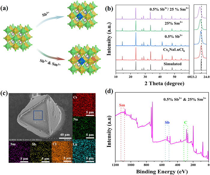
All the samples were synthesized via a typical hydrothermal method, and more details can be found in Supporting information. Fig. 1a shows the crystal structure of Cs2NaLuCl6, which crystallizes in cubic

|
Download:
|
| Fig. 1. (a) Crystal structure of pure Cs2NaLuCl6, Sb3+ singly-doped, Sm3+ singly-doped, and Sb3+/Sm3+-codoped samples. (b) XRD patterns of the as-synthesized samples. (c) SEM image and element mapping of 0.5%Sb3+/25%Sm3+-codoped Cs2NaLuCl6. (d) XPS of 0.5%Sb3+/25%Sm3+-codoped Cs2NaLuCl6 powders. | |
Then, the optical properties of the as-synthesized compounds were investigated. For pure Cs2NaLuCl6, it exhibits broad blue emission (Fig. S2 in Supporting information). After Sb3+ doping, the blue emission intensity is greatly improved, which should be attributed to the dopant induced STE in the [SbCl6]3− octahedron [19]. To demonstrates this, the excitation wavelength-dependent PL spectra were measured, and they show the similar spectral characteristics (Fig. S3a in Supporting information), and parallelly, the PLE spectra monitored at various emission wavelengths also exhibit identical profiles (Fig. S3b in Supporting information). Hence, the observed blue emission in Sb3+-doped Cs2NaLuCl6 stems from the same excited state. Moreover, Sb3+-doped Cs2NaLuCl6 also have a large Stokes shift of 138 nm, broad full width at half-maximum (FWHM) of 76 nm, and a long decay lifetime of 1.16 µs. Hence, we can attribute the broadband blue emission in Sb3+-doped Cs2NaLuCl6 to STEs [12,13]. Fig. S4 (Supporting information) shows the PL spectra with different Sb3+ doping concentrations. Clearly, the strongest emission for Sb3+ singly-doped Cs2NaLuCl6 can be obtained when the feed content of Sb3+ is 0.5%, and the corresponding PLQY is 98% and the PL decay lifetime is 1.16 µs. Fig. S5 (Supporting information) shows the PLE spectra of Sb3+ singly-doped Cs2NaLuCl6, and three different excitation bands at 267, 280, and 338 nm are observed, which can be assigned to the electronic transitions of 1S0 → 1P1, 1S0 → 3P2, and 1S0 → 3P1 of Sb3+, respectively [20]. Fig. S6 (Supporting information) shows the temperature-dependent emission spectra of 0.5%Sb3+ singly-doped Cs2NaLuCl6. Clearly, the single broad emission band can be observed within the entire testing temperature range (Fig. S6a). Moreover, the PL intensity decreases gradually with increasing of temperature, which should be attributed to the thermal quenching effect [8,21]. The exciton binding energy (Eb) was determined to be 77.7 meV (Fig. S6b), indicating that the electron-hole pair is a typical Frenkel-like exciton [22]. The Huang-Rhys factor (S) was calculated to be 20.0, which illustrates a strong electron-phonon coupling in Sb3+ singly-doped Cs2NaLuCl6 (Fig. S6c), which is conducive to the formation of STEs [23]. Moreover, the detailed photophysical mechanism of STE observed in Sb3+ singly-doped Cs2NaLuCl6 is given in Fig. S6d.
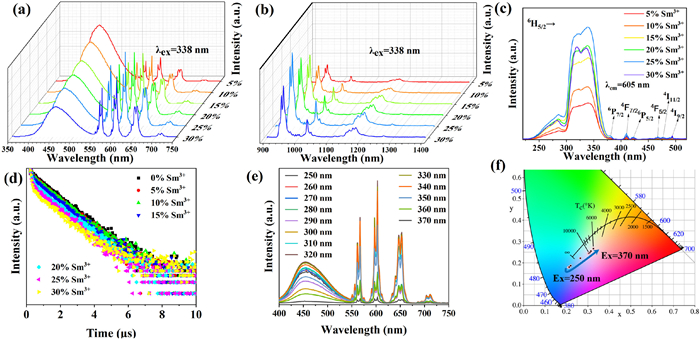
Figs. 2a and b show the PL spectra of Sb3+/Sm3+-codoped Cs2NaLuCl6 crystals. Clearly, the PL spectra of the codoped samples cover from visible to NIR light region. Besides the STE emission, there are multiple emission bands can be obtained, which corresponds to the 4G5/2 → 6HJ= 5/2,7/2,9/2,11/2 (563, 605, 657, and 709 nm), 4G5/2 → 6F5/2 (952 nm), 4G5/2 → 6F7/2 (1027 nm), 4G5/2 → 6F9/2 (1079 nm), and 4G5/2 → 6F11/2 (1267 nm) transitions of Sm3+, respectively. Moreover, we also synthesized Sm3+ singly-doped Cs2NaLuCl6, and the corresponding PL spectrum is given in Fig. S7 (Supporting information). Upon UV irradiation, the PL intensity of Sb3+/Sm3+-codoped Cs2NaLuCl6 is 54 times that of Sm3+ singly-doped Cs2NaLuCl6, which suggests that the emission intensity stems from 4f-4f transition of Sm3+ can be enhanced by Sb3+ sensitization [24]. Notably, the PL intensity of broadband STE emission decreases gradually at higher Sm3+ doping content, while the emission intensity stems from Sm3+ increases gradually with increasing of Sm3+ doping concentration (0-25%), which indicates a distinct ET from STE to Sm3+ [18]. When the doping concentration of Sm3+ is further increased, the luminescence intensity begins to decrease, which is caused by a typical concentration quenching effect [25,26]. Moreover, the optimal PLQY of 0.5%Sb3+/25%Sm3+-codoped Cs2NaLuCl6 in the visible light range is 74.58%, and more particularly, the PLQY in the NIR light region is 23.12%. Such high NIR PLQY in our system is higher than recently reported RE3+-doped all-inorganic non-rare earth-based DPs (Table S2 in Supporting information), which should be attributed to the similar ionic activity between Lu3+ and Sm3+, thus allowing more Sm3+ ions enter the host lattice and yields efficient NIR emission [27]. Fig. 2c shows the PLE spectra of Sb3+/Sm3+-codoped Cs2NaLuCl6, and the variation trend of PLE under different Sm3+ doping concentrations is in line with the change in PL intensity. Compared with Sb3+ singly-doped samples, there are additional PLE bands at 380, 410, 420, 468, 476, 494 nm in the Sb3+/Sm3+-codoped Cs2NaLuCl6 when monitored at 605 nm, which can be assigned to 6H5/2-6P7/2, 6H5/2-4F7/2, 6H5/2-6P5/2, 6H5/2-4F5/2, 6H5/2-4I11/2, 6H5/2-4I9/2 transitions of Sm3+ [28]. Apparently, the spectral overlap between STE emission and Sm3+ excitation can also be witnessed (Fig. S8 in Supporting information), illustrating the presence of Förster resonant ET from STE to Sm3+ [8]. Moreover, the PLE intensity below 360 nm is stronger than the intrinsic excitation bands of Sm3+, which enables a stronger PL intensity via ET from STE to Sm3+ (Fig. S8). Significantly, STE and Sm3+ emission have clear spectral overlap (Fig. 2a), and the characteristic PLE bands of both STE and Sm3+ can be witnessed in the PLE spectra of Sb3+/Sm3+-codoped Cs2NaLuCl6 (monitored at 605 nm, Fig. 2c). Hence, the above results fully demonstrate that the efficient emission of Sm3+ in the Sb3+/Sm3+-codoped Cs2NaLuCl6 stems from the ET of STE. As we know, Sb3+-induced STE emission shows a wide PLE band and intense absorption [29]. Thus, the ET from STE to Sm3+ can overcome the weak absorption of the forbidden 4f-4f transition and boost the PL intensity of Sm3+ [30]. In general, the emission of RE3+ with 4f-4f transition is sensitive to the excitation energy [31]. Nevertheless, the normalized PL spectra of Sb3+/Sm3+-codoped Cs2NaLuCl6 exhibit a similar spectral feature under 310-340 nm excitation (Fig. S9 in Supporting information). Thereby, the indirect excitation dominant excitation mechanism of Sm3+ in Sb3+/Sm3+-codoped Cs2NaLuCl6 [32].

|
Download:
|
| Fig. 2. PL spectra of Sb3+/Sm3+-codoped Cs2NaLuCl6 with various Sm3+ doping concentrations in (a) visible light region and (b) NIR light region (excited at 338 nm). (c) PLE spectra of Sb3+/Sm3+-codoped Cs2NaLuCl6 monitored at 605 nm. (d) PL decay lifetime of Sb3+/Sm3+-codoped Cs2NaLuCl6 monitored at 456 nm (STE emission band) under 320 nm laser excitation. (e) PL spectra of 0.5%Sb3+/20%Sm3+-codoped Cs2NaLuCl6 under various excitation wavelengths (250-370 nm). (f) CIE color coordinates of 0.5%Sb3+/20%Sm3+-codoped Cs2NaLuCl6. | |
In order to quantitatively describe the ET process from STE to Sm3+, we calculated the ET efficiency using the following equation:

|
(1) |
where τ0 and τ are the PL decay lifetime of STE without and with Sm3+ doping. Fig. 2d shows the PL decay lifetime of STE emission in the as-synthesized samples. For Sb3+ singly-doped Cs2NaLuCl6, the PL decay lifetime of STE is fitted by single-exponential function. Under influence the energy transfer from Sb3+ to Sm3+, the PL decay lifetime of STE in Sb3+/Sm3+-codoped Cs2NaLuCl6 is fitted by double-exponential function. Moreover, the PL decay lifetime of STE decreases gradually with increasing of Sm3+ doping content (Table S3 in Supporting information), which is accompanied by the increases of ET efficiency. When the ET efficiency reaches 72.89%, the Sm3+ exhibits the strongest emission. In particular, the ET efficiency from STE to Sm3+ in our Sb3+/Sm3+-codped Cs2NaLuCl6 is higher than other Sb3+/RE3+ codoped-DP systems (e.g., Sb3+/Ho3+-codped Cs2KInCl6 [8] and Sb3+/Yb3+-codoped Cs2AgInCl6 [33]) which ensures Sb3+/Sm3+-codped Cs2NaLuCl6 has highly efficient Sm3+ emission via ET. The PL decay lifetime of Sb3+/Sm3+-codped Cs2NaLuCl6 monitored at characteristic PL bands of Sm3+ show millisecond-scale lifetimes, which should be caused by the Laporte forbidden 4f-4f transitions (Fig. S10 in Supporting information) [32,34]. Moreover, the Sm3+ emission bands in Sb3+/Sm3+-codped Cs2NaLuCl6 exhibit different decay lifetimes, which should be attributed to the emission stems from the different emission sub-energy levels of Sm3+ [35]. Particularly, the PL decay lifetime decreases monotonously with increasing of Sm3+-doping concentration (Fig. S11 in Supporting information), which should be attributed to the increased nonradiative transition [36].
In our Sb3+/Sm3+-codoped system, the observed emission stems from STE and Sm3+ 4f-4f transitions, which makes this codoped compound has distinct excitation wavelength-dependent emission characteristics. Fig. 2e exhibits the PL spectra of 0.5%Sb3+/25%Sm3+-codoped Cs2NaLuCl6 under different excitation wavelengths, and the completely different spectral profiles can be seen in the visible light region, which enables this compound exhibits different emission colors. Fig. 2f shows the CIE coordinates of 0.5%Sb3+/25%Sm3+-codoped Cs2NaLuCl6 under various excitation wavelengths, which can change from (0.21, 0.18) under 250 nm excitation to (0.33, 0.26) under 370 nm irradiation, and the corresponding emission color turn from blue to white emission.
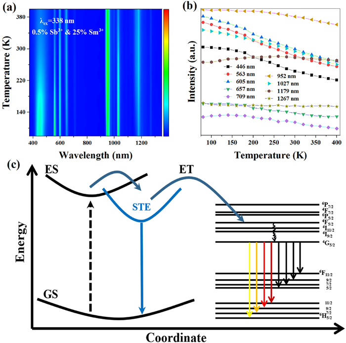
For a better understanding of the photophysical mechanism, the emission spectra of 0.5%Sb3+/25%Sm3+-codoped Cs2NaLuCl6 under various temperatures were collected in 80-400 K (Fig. 3a). Clearly, the characteristic bands of STE and Sm3+ emission can be witnessed in the measured temperature window (80-400 K). Fig. 3b summarizes the PL intensity under different temperatures. For the STE band in 0.5%Sb3+/25%Sm3+-codoped Cs2NaLuCl6, the PL intensity decreases gradually with the increase of temperature, which is similar to the phenomenon seen in 0.5%Sb3+-doped Cs2NaLuCl6 (Fig. S12 in Supporting information). Moreover, the STE emission intensity in 0.5%Sb3+/25%Sm3+-codoped Cs2NaLuCl6 has a faster decay rate than that in 0.5%Sb3+-doped Cs2NaLuCl6, which should be caused by the thermal-enhanced ET from Sb3+ to Sm3+. In particular, the PL intensity of Sm3+ characteristic bands under various temperature exhibits irregular change. Generally, the thermal quenching effect will lead to the decrease of luminous intensity of STE and Sm3+. However, the thermal-enhanced ET from STE to Sm3+ will further weaken the PL intensity of STE, but can boost the PL intensity of Sm3+ with increasing temperature. Under the influence of the above two factors, the PL intensity of Sm3+ characteristic bands show the unique PL characteristics in the temperature-dependent PL spectra, which is similar to Sb3+/Ho3+-codoped Cs2KInCl6 DP [8]. It is worth noting that when the temperature exceeds 300 K, although there is thermal-enhanced energy transfer from Sb3+ to Sm3+, the thermal quenching dominates the emission intensity of Sm3+. Therefore, when the temperature exceeds 300 K, the emission intensity of Sm3+ decreases gradually with increasing of temperature. The PL intensity of Sm3+ with different emission bands exhibits distinct degrees of attenuation, which can be assigned to the different sensitivity of the sub-energy levels of Sm3+ to temperatures.

|
Download:
|
| Fig. 3. Temperature-dependent PL spectra of 0.5%Sb3+/25%Sm3+-codoped Cs2NaLuCl6. (b) Emission intensity versus temperature. (c) Photophysical mechanism of Sb3+/Sm3+-codoped Cs2NaLuCl6. | |
Based on the above results, the possible photophysical mechanism of Sb3+/Sm3+-codoped Cs2NaLuCl6 can be summarized in Fig. 3c. Under UV photoexcitation, the electrons are excited from the ground state to the excited state. Subsequently, the excited electrons undergo the intersystem crossing from excited state to STE state due to the lattice distortion and intense electron-phonon coupling. Therefore, a broadband blue emission centered at 446 nm can be witnessed. Parallelly, the other part of electrons relaxes to the excited state of Sm3+ via the ET from STE to Sm3+, and then decay to the 4G5/2 level via the non-radiation transition process. Therefore, the multiple PL bands at, 563, 605, 657, 709, 952, 1027, 1179, and 1269 nm can be witnessed, which stems from the 4f-4f radiation transition of Sm3+ [37,38].
Moreover, the as-synthesized codoped compounds also have excellent stabilities. Taking 0.5%Sb3+/20%Sm3+-codoped Cs2NaLuCl6 as an example, its integral PL intensity remains basically unchanged after being stored in air for 3 months (Fig. S13 in Supporting information), and the XRD pattern exhibits an identical profile with the pristine one (Fig. S14 in Supporting information). Hence, 0.5%Sb3+/20%Sm3+-codoped Cs2NaLuCl6 has an outstanding chemical stability. Parallelly, the emission intensity of 0.5%Sb3+/20%Sm3+-codoped Cs2NaLuCl6 exhibits negligible changes after being light irradiation for 300 minutes (Fig. S15 in Supporting information), further confirming its remarkable photostability in the atmosphere.
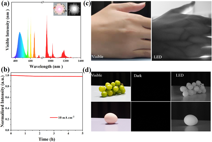
Given the remarkable stabilities and superior optical properties of Sb3+/Sm3+-codoped samples, a high-performance vis/NIR-LED was fabricated via coating 0.5%Sb3+/20%Sm3+-codoped Cs2NaLuCl6 on a 315 nm UV chip. Fig. 4a shows the electroluminescence (EL) spectrum of the as-fabricated device, and the inset shows the photographs of the operating device taken by visible (left) and NIR (right) cameras. Clearly, the EL spectrum covers the entire visible and near-infrared region, which echoes well with the emission spectra of Sb3+/Sm3+-codoped Cs2NaLuCl6. Moreover, the as-fabricated LED has the correlated color temperature (CCT) of 8270 K, color rendering index (CRI) of 75.8, and CIE coordinates of (0.30, 0.28). Also noteworthy, the as-fabricated device exhibits outstanding stability, and the EL intensity remains unchanged after operating for 5 h under 10 mA drive current (Fig. 4b). As we know, the NIR light has enormous application potential in biomedical imaging for its strong penetration, non-invasively, high resolution, and so forth. Thus, we demonstrated the application of the device in biomedical imaging in further proof-of-concept experiment. As shown in Fig. 4c, the palm in the daylight can be captured by the visible camera clearly. Since different tissues have different absorption for the NIR light, thus the distribution of veins in the palm can be captured clearly by the NIR camera when the as-fabricated LED starts to operate (Fig. 4c, right). In addition, the optical images of grapes and egg are taken by a visible camera under daylight (Fig. 4d, left), and nothing can be observed in the dark environment (Fig. 4d, middle). In particular, the black-and-white images of the grapes and egg can be witnessed when the LED was tuned on (Fig. 4d, right). Hence, the above results illustrate that the as-fabricated LED has great application potential in biomedical imaging and night vision.

|
Download:
|
| Fig. 4. (a) EL spectrum of as-fabricated 0.5%Sb3+/20%Sm3+-codoped Cs2NaLuCl6 based vis/NIR-LED under 315 nm chip excitation. The inset shows the optical images of the operating LED taken by visible (left) and NIR (right) cameras, respectively. (b) The long-term stability of as-fabricated device after operating for 5 hours. (c) The application of the as-fabricated device in biomedical imaging. (d) Photographs of grapes and egg illuminated by daylight and NIR-LED. | |
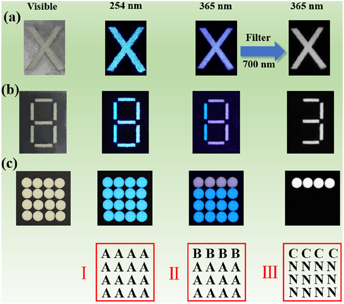
Recently, lead-free metal halides with unique PL characteristics have drawn much attentions in the field of smart photonics [39–44]. In our system, Sb3+/Sm3+-codoped Cs2NaLuCl6 exhibits broad emission that can cover visible light range and NIR light region, and has tunable emission color under different excitation wavelengths. This unique photophysical properties enable us to demonstrate its application in triple-mode fluorescence anti-counterfeiting and information encryption under different external stimuli. As illustrated in Fig. 5a, the alphabet of "X" was fabricated via filling Sb3+/Sm3+-codoped Cs2NaLuCl6 powders into the customized pattern templates. Upon 254 nm irradiation, the pattern "X" exhibits blue emission, and further change into white emission under 365 nm excitation. Particularly, when a 700 nm cutoff filter is added, the visible light is removed. Thus, the "X" pattern with NIR emission can be recorded by the NIR camera, and the triple-mode fluorescence anti-counterfeiting is realized based on Sb3+/Sm3+-codoped Cs2NaLuCl6 under different external stimuli. In order to further improve the diversity of fluorescent anti-counterfeiting, we fabricated a new pattern of "8" by combining Sb3+-doped Cs2NaLuCl6 and Sb3+/Sm3+-codoped Cs2NaLuCl6. As shown in Fig. 5b, the pattern "8" emits blue emission under 254 nm radiation. When the excitation wavelength is 365 nm, the number of "1" made by Sb3+-doped Cs2NaLuCl6 exhibits blue emission, and the number of "3" made by Sb3+/Sm3+-codoped Cs2NaLuCl6 shines white emission. Interestingly, with a 700 nm cutoff filter, the number "3" with NIR emission can be captured by the NIR camera. Subsequently, we further demonstrated the application of as-synthesized samples in multiple information encryption. As shown in Fig. 5c, we fabricated a PL dot array based on the combination of Sb3+-doped Cs2NaLuCl6 and Sb3+/Sm3+-codoped Cs2NaLuCl6. To be more specific, the Sb3+-doped Cs2NaLuCl6 is filled into the first line of the PL dot array, while the rest is filled with Sb3+/Sm3+-codoped Cs2NaLuCl6. Moreover, the blue point represents "A", the white point represents "B", the NIR point represents "C", and the non-emission represents "N". Hence, the detailed information encryption processes are given as follows: Under 254 nm excitation, all the PL dots exhibit blue emission, thus the Information I can be obtained. When the whole PL dot array is irradiated by 365 nm, the Information II can be transmitted, in which the blue dots on the first line and the white dots on the other position. Moreover, the PL dots with NIR emission on the first line can be captured by the NIR camera, and other position exhibit non-emission, resulting in the Information III. Notably, this multiple dynamic luminescence reported in our work under different external stimuli can apply more information encryption scenarios, thus greatly improving information security.

|
Download:
|
| Fig. 5. (a) Optical image of "X" pattern made by Sb3+/Sm3+-codoped Cs2NaLuCl6. (b) Optical image of the number "8" made by Sb3+-doped Cs2NaLuCl6 and Sb3+/Sm3+-codoped Cs2NaLuCl6. (c) Photographs of PL dot array made by Sb3+/Sm3+-codoped Cs2NaLuCl6 (first line) and Sb3+-doped Cs2NaLuCl6 (second, third, and fourth lines). | |
In summary, we synthesized Sb3+/Sm3+-codoped rare earth-based double perovskite Cs2NaLuCl6, and the obtained emission spectra can cover both visible light and NIR light regions, which stems from dopant induced STE emission and Sm3+ emission, respectively. The photophysical processes of Sb3+/Sm3+-codoped Cs2NaLuCl6 were discussed through steady-state/transient PL spectra and temperature-dependent PL spectra. The results show that Sb3+ can work as the sensitizer to enhance Sm3+ emission via ET from STE to Sm3+. Moreover, the similar ionic activity between Lu3+ and Sm3+ enables more Sm3+ doped into the host lattice. Thus, the efficient visible and NIR emission in Sb3+/Sm3+-codoped Cs2NaLuCl6 with PLQY of 74.58% and 23.12% can be obtained. Parallelly, the tunable emission characteristics of Sb3+/Sm3+-codoped Cs2NaLuCl6 were demonstrated in the visible light range, which can be tuned from blue (254 nm excitation) to white emission (365 nm excitation). Moreover, the visible emission can be removed through a 700 nm cut-off filter, and only the NIR emission can be captured by the NIR camera. Considering the remarkable stability and unique photophysical properties, we further demonstrated the application of Sb3+/Sm3+-codoped Cs2NaLuCl6 in high-performance NIR LED, triple-mode fluorescence anti-counterfeiting and information encryption. These findings provide deep insights for the further application of rare earth-based double perovskite in optoelectronic devices.
Declaration of competing interestThe authors declare that they have no known competing financial interests or personal relationships that could have appeared to influence the work reported in this paper.
AcknowledgmentsThe authors thank the Scientific and Technological Bases and Talents of Guangxi (Nos. Guike AD23026119, AD21238027), the Guangxi National Science Fundation Project (No. 2020GXNSFDA238004) and the "Guangxi Bagui Scholars" foundation for financial support.
Supplementary materialsSupplementary material associated with this article can be found, in the online version, at doi:10.1016/j.cclet.2023.109462.
| [1] |
Z. Chen, Q. Wang, Y. Tong, et al., J. Phys. Chem. Lett. 13 (2022) 4701-4709. DOI:10.1021/acs.jpclett.2c00076 |
| [2] |
C.Y. Zhong, L. Xiao, J. Zhou, et al., Chem. Eng. J. 431 (2022) 134110. DOI:10.1016/j.cej.2021.134110 |
| [3] |
T. Milstein, D. Kroupa, D. Gamelin, Nano Lett. 18 (2018) 3792-3799. DOI:10.1021/acs.nanolett.8b01066 |
| [4] |
Y. Liu, M.S. Molokeev, Z. Xia, Energy Mater Adv. 2021 (2021) 2585274. |
| [5] |
A. Zhang, Y. Liu, G. Liu, et al., Chem. Mater. 34 (2022) 3006-3012. DOI:10.1021/acs.chemmater.1c03878 |
| [6] |
Y. Liu, A. Nag, L. Manna, et al., Angew. Chem. Int. Ed. 60 (2021) 11592-11603. DOI:10.1002/anie.202011833 |
| [7] |
Y. Mahor, W. Mir, A. Nag, J. Phys. Chem. C 13 (2019) 15787-15793. |
| [8] |
W. Huang, H. Peng, Q. Wei, et al., Adv. Opt. Mater. 11 (2023) 2203103. DOI:10.1002/adom.202203103 |
| [9] |
X. Li, D. Wang, Y. Zhong, et al., Adv. Sci. 10 (2023) 2207571. DOI:10.1002/advs.202207571 |
| [10] |
S. Ji, R. Li, H. Huang, et al., Light Sci. Appl. 11 (2022) 52. DOI:10.1038/s41377-022-00739-2 |
| [11] |
Y. Liu, X. Rong, M. Li, et al., Angew. Chem. Int. Ed. 59 (2020) 11634-11640. DOI:10.1002/anie.202004562 |
| [12] |
H. Arfin, J. Kaur, T. Sheikh, et al., Angew. Chem. Int. Ed. 59 (2020) 11307-11311. DOI:10.1002/anie.202002721 |
| [13] |
S. Saikia, A. Joshi, H. Arfin, et al., Angew. Chem. Int. Ed. 61 (2022) e202201628. DOI:10.1002/anie.202201628 |
| [14] |
Y. Wang, S. Bai, J. Sun, et al., J. Alloys Compd. 947 (2023) 169602. |
| [15] |
W. Gan, L. Cao, S. Gu, et al., Chem. Mater. 35 (2023) 5291-5299. DOI:10.1021/acs.chemmater.3c00446 |
| [16] |
N. Liu, W. Zheng, R. Sun, et al., Adv. Funct. Mater. 32 (2022) 2110663. DOI:10.1002/adfm.202110663 |
| [17] |
E. Cui, X. Yuan, L. Tang, et al., Appl. Surf. Sci. 609 (2023) 155472. DOI:10.1016/j.apsusc.2022.155472 |
| [18] |
W. Gan, B.M. Liu, L. Huang, et al., Adv. Opt. Mater. 10 (2022) 2102851. DOI:10.1002/adom.202102851 |
| [19] |
G. Zhang, P. Dang, L. Tian, et al., Adv. Opt. Mater. 11 (2023) 2202369. DOI:10.1002/adom.202202369 |
| [20] |
Y. Chen, L. Zhou, S. Zhou, et al., Inorg. Chem. 62 (2023) 2806-2816. DOI:10.1021/acs.inorgchem.2c03961 |
| [21] |
H. Peng, S. Yao, Y. Guo, et al., J. Phys. Chem. Lett. 11 (2020) 4703-4710. DOI:10.1021/acs.jpclett.0c01162 |
| [22] |
B. Yang, K. Han, J. Phys. Chem. Lett. 12 (2021) 8256-8262. DOI:10.1021/acs.jpclett.1c01828 |
| [23] |
H. Peng, B. Zou, J. Phys. Chem. Lett. 13 (2022) 1752-1764. DOI:10.1021/acs.jpclett.1c03849 |
| [24] |
J. Sun, W. Zheng, P. Huang, et al., Angew. Chem. Int. Ed. 61 (2022) e202201993. DOI:10.1002/anie.202201993 |
| [25] |
X. He, H. Peng, Q. Wei, et al., Aggregate (2023) e407. |
| [26] |
S. Ge, H. Peng, Q. Wei, Adv. Opt. Mater. 11 (2023) 2300323. DOI:10.1002/adom.202300323 |
| [27] |
Y. Wang, S. Bai, J. Sun, et al., J. Alloy. Compd. 934 (2023) 167952. DOI:10.1016/j.jallcom.2022.167952 |
| [28] |
F. Locardi, E. Gianotti, I. Nelli, et al., Mater. Res. Bull. 86 (2017) 220-227. DOI:10.1016/j.materresbull.2016.11.011 |
| [29] |
H. Peng, Y. Tian, Z. Yu, et al., Sci. China Mater. 65 (2022) 1594-1600. DOI:10.1007/s40843-021-1937-y |
| [30] |
J. Ni, B. Zhou, S. Fang, Chem. Mater. 34 (2022) 6288-6295. DOI:10.1021/acs.chemmater.2c00333 |
| [31] |
S. Li, Q. Hu, J. Luo, et al., Adv. Opt. Mater. 7 (2019) 1901098. DOI:10.1002/adom.201901098 |
| [32] |
J. Nie, H. Li, S. Fan, et al., Cell Rep. Phys. Sci. 3 (2022) 100820. DOI:10.1016/j.xcrp.2022.100820 |
| [33] |
L. Cao, X. Jia, W. Gan, et al., Adv. Funct. Mater. 33 (2023) 2212135. DOI:10.1002/adfm.202212135 |
| [34] |
W. Yang, P. Dang, G. Zhang, et al., Adv. Opt. Mater. 11 (2023) 2300468. DOI:10.1002/adom.202300468 |
| [35] |
P. Dang, Z. Zhang, W. Yang, et al., Chem. Mater. 35 (2023) 1640-1650. DOI:10.1021/acs.chemmater.2c03246 |
| [36] |
B. Su, M. Li, E. Song, et al., Adv. Funct. Mater. 31 (2021) 2105316. DOI:10.1002/adfm.202105316 |
| [37] |
C. Chen, M. Jin, J. Xiang, et al., Ceram. Int. 49 (2023) 25232-25239. DOI:10.1016/j.ceramint.2023.05.056 |
| [38] |
S. Han, D. Tu, Z. Xie, et al., Adv. Sci. 9 (2022) 2203735. DOI:10.1002/advs.202203735 |
| [39] |
S. Feng, Y. Ma, S. Wang, et al., Angew. Chem. Int. Ed. 134 (2022) e202116511. DOI:10.1002/ange.202116511 |
| [40] |
B. Zhou, G. Xiao, D. Yan, Adv. Mater. 33 (2021) e2007571. DOI:10.1002/adma.202007571 |
| [41] |
B. Zhou, D. Yan, Adv. Funct. Mater. 33 (2023) 2300735. DOI:10.1002/adfm.202300735 |
| [42] |
Y.J. Ma, G. Xiao, X. Fang, et al., Angew. Chem. Int. Ed. 62 (2023) e202217054. DOI:10.1002/anie.202217054 |
| [43] |
S. Liu, Y. Lin, D. Yan, Sci. Bull. 67 (2022) 2076. DOI:10.1016/j.scib.2022.09.025 |
| [44] |
F. Nie, B. Zhou, K.Z. Wang, et al., Chem. Eng. J. 430 (2022) 133084. DOI:10.1016/j.cej.2021.133084 |