 2024, Vol. 35


In recent years, environmental pollution and energy crises have attracted increasing scholarly attention due to the negative effect and non-renewability of fossil fuels. As a result, using sustainable clean energy sources to replace fossil fuels and developing efficient energy storage technologies to prevent future energy crises have attracted considerable scholarly attention [1–5]. At present, the demand for electric vehicles and portable electronic devices has led to increasing demand for secondary batteries [6–9]. Lithium-ion batteries (LIBs) with a long cycling lifespan, which have been commercialized for over 30 years, still play an indispensable role in electrochemical energy storage [10,11]. However, traditional LIBs cannot meet the requirements of electric vehicles (500 km) due to their low capacity [12,13]. Researchers have found that the theoretical specific capacity of lithium metal batteries (LMBs) is 3860 mAh/g, which is tenfold higher than the specific capacity of graphite electrodes in LIBs (372 mAh/g), and they have low redox potential (−3.04 V vs. standard hydrogen electrode, SHE) [14–17]. Therefore, lithium metal batteries are expected to solve the problems caused by the low capacity of LIBs. The use of LMBs as energy storage was first studied compared with LIBs. The first attempt to use LMBs can be traced back to 1913 when G. N. Lewis and F. G. Keyes successfully tested the electrode potential [18,19]. However, the development of LMBs was limited by the problems of dendrites and volume expansion during charging and discharging [20]. Subsequently, Auborn and Barberio used LiMoO2 and MoO2 (or WO2) as electrodes to assemble the battery without lithium metal [21]. In 1980, Goodenough et al. reported that layered oxides could significantly promote the commercialization of LIBs [22,23]. After SONY successfully commercialized LIBs using flexible carbon as an anode and LiCoO2 as a cathode [24], the research on LMBs cells gradually decreased (Fig. 1).

|
Download:
|
| Fig. 1. The development history of various metal batteries. | |
Currently, the increasing price of lithium due to its low reserve and uneven distribution of its resources limits the large-scale application of lithium batteries in electrical appliances [25]. However, other metals, including sodium [26], potassium [27], zinc [28], and magnesium [29], have been considered promising alternatives to lithium metals owing to their relative abundance and inexpensiveness. In addition, studies have shown that sodium metal batteries (SMBs), potassium metal batteries (PMBs), zinc metal batteries (ZMBs), and magnesium metal batteries (MMBs) have satisfactory capacities [30–32]. Among them, the theoretical specific capacity of sodium metal is approximately 1165 mAh/g, and its redox potential (−2.75 V vs. SHE) is relatively higher than that of lithium metal [33–36]. In 1980, Newman and Klemann completed 16 stable cycles of Na metal as a pair of electrodes [37]. However, the safety problems caused by dendrites could not be solved in the early stage, thus somewhat limiting the development of SMBs [24,38]. In 2013, Adelhelm et al. [39] first reported rechargeable Na-O2 batteries at room temperature, which advanced the development of SMBs. Potassium metal, which is in the same element group as Li and Na, has a redox potential of −2.93 V (vs. SHE) and theoretical specific capacity of 687 mAh/g [40,41]. Compared with lithium and sodium batteries, K batteries are new emerging batteries [42,43]. The concept of potassium-ion batteries was first reported in 2004. After years of hard work, K-O2 batteries were first reported by Wu et al. in 2013 [39]. Beyond monovalent metals, Zn as a divalent metal has a redox potential of −0.76 V (vs. SHE) and a specific capacity of 820 mAh/g [44–48]. Zn was first used as anode in batteries in 1799 when the Zn-MnO2 battery was first assembled, but its further development was shelved because of its short life [49]. Another typical Zn-based battery called Zn-O2 battery was first proposed in 1868 [36,39,50-52]. Similarly, magnesium metal has a redox potential of −2.37 V and a specific capacity of 2205 mAh/g (vs. SHE) [53]. The concept of MMB was first introduced in 1990 and assembled in 2000. Further research on MMB is required to effectively explore its performance [39].
Metal batteries have gained increasing attention from researchers owing to their low reduction voltage and high specific capacity [54,55]. We briefly compared the performance of five different metal materials (Li, Na, K, Zn, and Mg) commonly used as battery anodes and the partial performance of M-O2, M-CO2, and M-S batteries made of those metal anodes (Fig. 2) [32,56,57]. Na, K, Zn, and Mg are comparable to Li in storage and have better safety performance as anodes in metal batteries. Among the M-O2 batteries, the Mg-O2 battery exhibits theoretical specific energy comparable to Li-O2. In addition, the other four metals in the M-CO2 battery have life spans better than the life span of Li-CO2. Similarly, the theoretical volumetric energy density of Mg-S batteries is higher than that of lithium metal batteries. Therefore, these four metals also have broad development prospects similar to the mainstream Li.

|
Download:
|
| Fig. 2. Performance comparison of metal batteries. | |
However, the applications of metal batteries are still limited by many security risks caused by the growth of dendrites on anodes [58–60]. Therefore, effective inhibition of the dendrites formation is of great significance for metal batteries. The primary reason of dendrite formation is natural properties of anode and electrolyte. The electrolyte is classified into solid and liquid electrolytes. Due to technical problems, holes and defects may be formed in the internal structure of the solid electrolyte during its manufacturing process [61–63]. These defects and voids unbalance the pressure of the electrolyte; as a result, large amounts of electrons gather close to the lower pressure to promote the nucleation of the metal, thus generating dendrites [64]. In addition, the uneven distribution of metal ions in liquid electrolytes facilitates the formation of dendrites in areas with high ion density during nucleation [65,66]. The uneven surface of the anode during the manufacturing process promotes dendrite formation [67]. When the solid electrolyte contacts the uneven surface of the anode, it will easily destroy the microstructure and uniformity of the anode/electrolyte interface, thus promoting the dendrites formation [68,69]. In addition, the contact between the uneven surface of the anode and the liquid electrolyte leads to the tip discharge effect, attracting more metal ions, thus facilitating the formation of dendrites (Fig. 3a) [70,71].

|
Download:
|
| Fig. 3. (a) Schematic diagram of dendrite growth. (b) Types and (c) functions of MOFs. | |
To solve the dendrite problems associated with metal batteries, researchers have adopted different technologies to improve the service life of metal batteries. These technologies mainly focus on three aspects: electrolyte, diaphragm, and metal anode. In terms of solid electrolytes, physical methods can be used to reduce the holes and pores in the electrolyte and compress the space for dendrite growth. In addition, solid electrolytes can be optimized by increasing the relative density [72]. Meanwhile, modification of the grain boundary [73–75], modulation of electronic conductivity [76], and doping of functional components are effective methods to improve the solid electrolyte and inhibit the growth of dendrite [77–79]. Additionally, introducing additives to the liquid electrolyte to promote the uniform distribution of ions can reduce the security risk caused by dendrites [70,71]. Problems caused by dendrites can also be minimized by optimizing the solid electrolyte interphase (SEI) layer. Diaphragm materials can be roughly divided into three types: inorganic [80,81], organic [82,83], and hybrid material [84]. In the liquid electrolyte, the optimized diaphragm material can independently screen particles, providing a green channel for the quick passage of metal ions and evenly distributing the metal ions on the anode surface.
Anode surface coating is an effective and simple method to protect the anode [85–87]. Commonly used coating materials include oxide coatings [88–90], single-element deposition [91,92], organic polymer coatings [93–96], and other functional materials [97–100]. Currently, using functional materials to solve problems like dendrite formation in metal batteries has been proved to be an effective strategy. There are a rich variety of functional materials, such as MXene, COFs, graphene [101,102]. Compared with those two-dimensional (2D) materials, the three-dimensional (3D) spatial structure of MOFs can provide a larger specific surface area and more pores, which can offer more spatial sites for the anode reaction [103]. In addition, the in-situ growth of MOFs can be realized simply and affordably in comparison with materials such as graphene. Moreover, the particle size and pore size of MOFs can be controlled by some simple and economical methods [104]. Therefore, MOFs are commonly used as precursors to prepare carbonaceous materials with three-dimensional structures in modifying metal anodes. MOFs are an important branch of carbon source materials, which mainly comprise central metal elements (Zn, Co, Cu, and Fe) and functional ligands (Fig. 3b). MOFs are mainly divided into four categories with unique geometric shapes and porosity. Isoreticular metal-organic frameworks (IRMOFs) is a self-assembled microporous crystal material in the form of an octahedron structure [105,106]. Zeolitic imidazolate frameworks (ZIFs) is a tetrahedral structure material comprising divalent metal and deprotonated imidazole chains [107]. Materials of Institut Lavoisiers (MILs) are produced using transition metal elements and dicarboxylic acid ligands, such as glutaric acid and succinic acid, which have 3D skeleton structures with microporous channels and cage structures [108,109]. Porous coordination networks (PCNs) are materials containing multiple cubic octahedral nanoporous cage structures [110]. MOFs have been widely applied in energy storage devices, such as various metal batteries owing to their controllable topological structures, great specific surface area, and high thermal stability [111,112]. For example, after adding carboxyl to UiO-66, Zhu et al. [113] introduced the resultant product to the anode interface of the aqueous zinc battery, and the cycle life of the half battery at 2 mA/cm2 and 2 mAh/cm2 exceeded 2800 h. Moreover, the full battery maintained 91% capacity after 2400 cycles at 1 A/g. The addition of a carboxyl group to the anode increased the ion transfer rate and affinity for Zn2+. Moreover, the channel formed by the carboxyl facilitated the diffusion of electrolytes and the insertion and extraction of Zn2+, thus improving the cycle stability of batteries. Therefore, the addition of MOFs increases reaction kinetics and reduces nucleation potential energy, and induces uniform deposition of metal ions (Fig. 3c). MOFs have stable spatial structure and controllable pore size. The stable structure ensures stable performance throughout the battery cycle, and the large specific surface provides more reaction sites for metal ion deposition to guide its uniform deposition. Additionally, the Lewis acid sites in MOF structures can effectively improve ion transport. As a result, numerous researchers have applied MOF and its derivatives to the metal anode interface to reduce dendrite formation and improve the properties of metal batteries.
Many reviews have discussed anode modification in metal batteries [114–117]. Hu [118] and Peng [119] mainly discussed the application of MOFs in electrolytes and cathodes for Li, Na, and Zn batteries. However, few reviews have exclusively reported the application of MOFs on the anode interface of various metal batteries. This paper first summarizes the synthesis methods of typical MOFs and their derivatives. It also elucidates the role and principle of MOFs and their derivatives on the anode interfaces, such as Li, Na, K, Zn, and Mg, in metal batteries. This review would provide guideline for the design and application of MOFs to the anode interface in metal batteries.
2. Synthesis methods of MOFsMOF materials generally comprise two parts: the organic ligand as the column and the metal center as the node [120,121]. As a result, various synthesis methods are used to produce MOF materials. In the early 2000s, many scientists used hydrothermal or solvothermal methods to synthesize MOF powders. With the development of MOF materials, some primary preparation methods can no longer meet the need of researchers. Thus, the preparation of thin film MOFs can be upgraded. To meet the protective requirements, several scientists have recently prepared MOF derivatives to enlarge the porosity and specific surface area of MOFs by modifying the preparation methods [122,123]. This section summarizes the synthesis methods of MOFs and their derivatives powders and the construction methods of protective MOF thin films on metal anodes (Fig. 4).

|
Download:
|
| Fig. 4. Preparation of MOFs and construction of MOF thin films. | |
MOF powders are mainly prepared using solvothermal and hydrothermal methods. The most commonly used organic solvents in solvothermal synthesis are methanol, ethanol, and N,N-dimethylformamide (DMF). Generally, the required precursors are combined with a certain proportion of organic solvents, heat the mixture in an oil bath pot or a reaction kettle for some time, and then centrifuge to produce MOF powder. Zeng et al. [124] used Zn(OAc)2·2H2O as a metal donor and the mixture of DMF and ethanol as an organic solvent. Then, they mixed Zn(OAc)2·2H2O, H2BDC, and polyvinylpyrrolidone (PVP) with organic solvent and heated to obtain MOF-5. In some special cases, the reaction can be performed at room temperature, which is called the low-temperature solvothermal reaction. Wang et al. [125] used zinc foil added to the tris(1-chloro-2-propyl)phosphate (TCPP) ligand and the mixed organic solution to produce Zn tetra-(4-carboxyphenyl)porphyrin (denoted as Zn-TCPP), within a few minutes. A hydrothermal method is used to synthesize MOF powder by using water as a solvent and corresponding materials as precursors. The precursors are heated, reacted for some time, and dried in a vacuum. MOF powder can be obtained by directly mixing the corresponding precursor with water and heating it. Xu et al. [126] selected NH2-MIL-125(Ti) as the precursor. The precursor was dissolved in water, heated at 150 ℃ for 24 h, and dried in a vacuum to produce Ti-MOF. MOF powder can also be synthesized by adding a metal donor and a precursor to water, followed by mixing and heating. Kim et al. [127] used 1,2,4,5-benzene tetracarboxylic acid (BTEC) as a precursor and zirconium tetrachloride (ZrCl4) as a metal donor and dissolved them in water and heated to obtain Zr-MOF.
2.1.2. Synthesis methods of MOF derivative powdersMOF derivative powders are mainly prepared using two methods: (1) By modifying the preparation process of MOF materials, that is, by adding substances that can composite with the metal donors into the organic solvent during the preparation process. When preparing ZIF-8 materials, Gan et al. [128] added Zn(NO3)2·6H2O and dimethyl imidazole into the organic solvent, and then added GO suspension to the mixed solution. After the mixed solution was allowed and dried, a composite material ZIF-8@GO was obtained. (2) Another method of preparing MOF derivatives is by carbonizing the prepared or pretreated MOF materials. Xin et al. [129] first carbonized ZIF-8 and then sulfurized it to obtain ZnS. Then, the obtained ZnS was subjected to a solvothermal reaction and dried in a vacuum to obtain ZnS/NC.
2.2. Synthesis of MOF and derivative thin film 2.2.1. In-situ preparation methodsIn-situ preparation methods are mainly prepared using three methods: (1) In-situ crystallization is a method in which a growth substrate is added to the mixed solution of precursor and organic solvent during the solvothermal or hydrothermal process. When the solvothermal or hydrothermal process is completed, the substrate is collected from the surface of the substrate and cleaned with organic solvent. Liu et al. [130] soaked zinc foil in a mixture of 2-methylimidazole and methanol. ZIF-8 film was prepared on the surface of zinc foil by heating reaction. This method is more suitable for the construction of MOF thin films whose basis material is the same as the central metal atom of MOFs. (2) In the secondary growth and crystallization method, a layer of a metal donor is prepared on the surface of the substrate to be coated. After the substrate material is taken as a metal donor for solvothermal or hydrothermal reaction, the metal donor layer finally converts into the required MOF thin film. Cui et al. [131] added zinc foil into the mixed solution of Zn (CH3COO)2·2H2O and NaOH to obtain Zn@ZnO foil, and placed it in 2-methylimidazole and reacted for 24 h, and the Zn@ZIF-8 foil was obtained. This method is more suitable for the construction of MOF thin film whose basis material activity is lower than or the same that of MOFs central atom. (3) Electrochemical deposition refers to the technology in which the positive charges (metal ion) and the negative charges (organic solvent) in the electrolyte undergo a redox reaction on the electrode surface through current transfer under the action of an external electric field, thereby forming a layer of coating on the metal surface. Zhang et al. [53] used a two-electrode system in the deposition process, using a graphite rod as the counter electrode. The Mg foil was immersed in the solvent solution, and the appropriate voltage and plating time were selected to make the ZIF-8 layer completely cover the entire Mg surface. This method is mostly used when the valence of the base metal is higher than or equal to the valence of the central atom. It is vital to control the voltage and set the deposition time during the plating process, therefore it is not easy to control the deposition thickness.
2.2.2. Ex-situ preparation methodsEx-situ preparation methods are mainly prepared using two methods: (1) Doctor blading method is the most extensively used method for preparing thin films from MOFs and MOF derivatives powders. Powders and binders are added into an organic solvent, and the mixed solution is then added dropwise to the substrate and scraped flat with a scraper. Then the solvent is evaporated to generate a thin film on the surface of the substrate, and the thickness of which is mainly determined by the scraper. Zhang et al. [132] mixed the resulting Al2O3@MOF-C with PVDF in a ratio of 8:2. The mixed solution was then scraped onto the substrate and then dried at 100 ℃ for 10 h to obtain Al2O3@MOF-C films. (2) In the spin-coating method, powders of MOFs and MOF derivatives are added to binders. This method is a process that depends on the gravity and centrifugal force generated when the workpiece rotates to evenly distribute the mixed solution falling on the substrate surface. The thickness of the film is related to the viscosity of the solvent and the rotation speed of the workpiece, and the main advantage of the film prepared by this method is that it is convenient to obtain a dense coating with uniform thickness. Fan et al. [133] uniformly grew Zn-MOF in situ on the basal surface. The PVA gel was then penetrated to the Zn-MOF surface by spin coating. Zn-MOF and PVA were tightly linked to the substrate to prepare Zn-MOF@PVA films.
3. Li metal anodeLMB is a kind of Li battery, and it was invented earlier than LIBs that have been commercially produced in large quantities. However, its development was hindered because the dendrite problem was not well solved in the early stage. To meet the requirement for green energy sources, LMB with great energy density has attracted extensive attention from researchers. In addition, with the development of various coating materials, more solutions are proposed to solve the problem of Li dendrite formation. The selected protection materials for the Li metal anode must meet the following requirements: (1) A suitable pore size for Li-ion free movement without obstruction; (2) A Li affinity that can reduce the energy required for the Li nucleation; (3) Adequate internal space for Li storage [134]. Many researchers have investigated MOFs with the above characteristics to protect the Li metal anode.
3.1. Protection by monometallic MOFs and their derivatives 3.1.1. Zn-MOFs and their derivativesZn-based MOFs have been applied to LMB because of their structural stability and reducing the binding energy of Li+ to form Li metal. In 2020, Zhang et al. [133] fabricated a composite anode by using spin-coating methode on the Li metal after mixing Zn-MOF with polyvinyl alcohol (PVA) adhesive. In subsequent electrochemical testing, the Cu@Zn-MOF@PVA@Li electrode exhibited more stable Coulombic efficiency (CE) and longer expected life than the bare electrode. Channels and central metal elements provided by Zn-MOF can shield the hindrance of anions to lithium ions and accelerate their migration. The direct combination of MOFs with metal anodes through the spin-coating process is one of the simplest methods.
The poor direct composite effect of MOFs and Li metal anode can be solved by introducing other intermediate materials. For example, in 2022, Li et al. [135] grew ZIF-8 on oxidized polyacrylonitrile (PAN) nanofibers and obtained OPANF@ZIF-8. Li was compounded with OPANF@ZIF-8 to examine its role in inhibiting dendrite formation. Symmetrical batteries were assembled using OPANF@ZIF-8 and Cu as electrodes. The analysis and testing revealed that batteries equipped with OPANF@ZIF-8 electrodes had more stable performance compared with a Cu electrode. EIS analysis revealed that Li was uniformly deposited on the anode surface with OPANF@ZIF-8 addition. Therefore, Rct decreased and remained stable after 100 cycles. The binding energies of acridone ring, naphthidine ring, hydronaphthidine ring and ZIF-8 with Li atom (Fig. 5a) were simulated by density functional theory (DFT). The results showed that the functional group on the surface of OPANF/ZIF-8@Cu can effectively promote the adsorption of Li. In order to verify the feasibility of the calculated results, the deposition of Li at 0.1, 1, 3, and 5 mAh/cm2 current densities was monitored by scanning electron microscope (SEM). In the picture, it can be clearly observed that Li was uniformly and orderly deposited on the surface of OPANF/ZIF-8@Cu (Fig. 5b). This phenomenon indicated that OPANF/ZIF-8@Cu can effectively improve the affinity for Li and control the uniform distribution of Li. According to the schematic diagram of Li deposition drawn by the calculated and experimental results (Fig. 5c), Li+ was adsorbed on the surface of PAN nanotubes and deposited on the surface of PAN in an orderly manner under the action of ZIF-8 to avoid the formation of dendrites. In a subsequent full-battery test, the Li-OPANF/ZIF-8@Cu electrode retained 86% of its capacity after 120 cycles and had a CE of 98.7% at 0.5 C (Fig. 5d).

|
Download:
|
| Fig. 5. (a) The interactions between Li atom and acridone ring, naphthidine ring, hydronaphthyridine ring and ZIF-8 were calculated by DFT. (b) Schematic diagram of Li deposition process in OPANF/ZIF-8@Cu. (c) SEM image of top view and cross section of OPANF/ZIF-8@Cu anode after deposition of Li metal, with capacities of (ⅰ, ⅱ) 0.1 mAh/cm2, (ⅲ, ⅳ) 1 mAh/cm2, (ⅴ, ⅵ) 3 mAh/cm2 and (ⅶ, ⅷ) 5 mAh/cm2. (d) Cycle performance of Li-OPANF/ZIF-8@Cu full battery at 0.5 C. Copied with permission [135]. Copyright 2022, Elsevier. | |
Carbonization is a feasible method for enhancing the property of MOFs. Some elements, such as N, are added to the amorphous carbon skeleton during carbonization to enhance the conductivity. In addition, a cavity structure will be formed during the carbonization process, which would be beneficial for the storage of lithium. In 2020, Kim et al. [136] carbonized ZIF-8 as the precursor to prepare porous carbon framework (PCF) material with a very high affinity for Li+ and etched it in an HCl solution to obtain PCF-E. After PCF and PCF-E were combined with metal Li anodes, the performance of PCF and PCF-E was superior to that of another porous carbon material during Super-P battery cycling testing. During the cycling, the capacity of the battery combined with PCF-E was more than 3 mAh/cm2. At the 0.2 mAh/cm2 cycle test, the Super-P experienced a voltage spike after approximately 88 cycles, at which point the battery failed due to dendrite growth and exhaust problems. The LMB combined with PCF and PCF-E maintained stable cyclic behavior in 268 cycles and 350 cycles, respectively. The cyclic stability behavior of the PCF and PCF-E-combined LMB was owe to the larger specific surface area and porosity of PCF-E, which provided more assistance for lithium adsorption and reduced the hidden dangers of dendrite growth. The analysis of AC impedance testing reveals that the presence of internal pores can be chemically used for metallization reactions. Therefore, having a larger pore volume inside can improve the reversibility of the battery during cycling, providing lower nucleation overpotential. In addition to the central element being lithophilic, the comparison of the cycling performance between PCF and PCF-E also confirms that the porous structure is an important factor in improving battery performance. In the same year, Feng et al. [137] also reported a material with a large surface area, which was calcined for 5 h in a tubular furnace in a vacuum environment using ZIF-8 as a precursor and industrial foam copper to obtain N/O dual-doped 3D porous carbon framework (NOCA@CF). When Li was deposited on NOCA@CF, its cycle life was 400 h in a symmetrical battery, which was much longer than the battery using Li@CF as the electrode (50 h). The improved life cycle of the NOCA@CF battery was because its specific surface area reduced the local current density and made the electric field distribution more uniform, which effectively induced the uniform deposition of metal ions.
In 2021, Wang et al. [138] first grew ZIF-8 on an electrospinning fiber called PAN/2-MIZ and then carbonized it to obtain the NHCF@CN@ZnO product. Afterward, the obtained product was combined with Li. They performed the same carbonization treatment on the electrospinning fiber to obtain product NCF and composited with Li as the control group. Compared with NCF, NHCF@CN@ZnO had a larger specific surface area and pore size distribution, which reduced local current density and effectively regulated Li deposition. Therefore, at 5 mA/cm2 and 5 mAh/cm2, a symmetrical battery with NHCF@CN@ZnO@Li as the electrode can achieve cycling for 1000 h. The performance test of a whole battery using commercial LiFePO4 (LFP) as the cathode (0.5 C) showed the average CE of the NHCF@CN@ZnO@Li||LFP battery remained at 99.52% over 500 cycles. In contrast, the specific capacity decreased to 64.9 mAh/g for all cells after 500 cycles in NCF@Li||LFP.
Several studies have also reported the enlargement of the pore distribution ratio and specific surface area of MOFs through different carbonization techniques to improve the lithophilicity of materials. Zhang et al. [139] grew ZIF-8 with a hollow structure (h-ZIF-8) and ordinary ZIF-8 on carbon cloth (CC). These two materials were carbonized in N2 to obtain ZNCC and h-ZNCC. The protective performance of h-ZNCC and ZNCC on the battery was tested by assembling a half cell. The result showed that Li could be stably plated/peeled on h-ZNCC for 3000 h, and the potential of ZNCC began to change dramatically after 500 h at 5 mA/cm2 and 5 mAh/cm2. In addition, h-ZNCC maintained a low hysteresis voltage of 68 mV for 4100 h at 10 mA/cm2@10 mAh/cm2. Zhong et al. [140] carbonized ZIF-8 in Ar atmosphere and covered the surface of Li metal to obtain CF@NCZ. The half-battery test revealed that the voltage fluctuation of CF@NCZ was minimal at 5 mA/cm2@5 mAh/cm2, and its lifespan was 1600 h.
In addition, Tan et al. carbonized ZIF-8 and CC in a tube furnace to produce ZNCC. The obtained product was soaked in melted Li metal in a glove box and cooled to produce the battery anode ZNCC@Li [141]. Meanwhile, they cooled the melted Li metal on the CC in the same way to produce a comparative anode CC@Li. First, from the symmetrical unit test from 1 mA/cm2 to 10 mA/cm2@1 mAh/cm2, ZNCC@Li exhibited excellent cyclic stability. Afterward, LiNi0.5Mn1.5O4 (LMNO) was used as the cathode to assemble the entire battery. After 180 charge-discharge cycles at 1 C, ZNCC@Li maintained an output capacity of 104.6 mAh/g, while the capacity of CC@Li decreased to 50.0 mAh/g. It was because the content of pyridine nitrogen and pyrrole nitrogen in ZNCC was much higher than that in CC. The nitrogen and Li-ion had good interaction and large binding energy.
Liu et al. [142] first grew zinc organic skeleton nanosheets (ZIF-L) in-situ on CC. Subsequently, the obtained materials were calcined at 400 ℃ in a Muffle furnace to obtain CC@ZnO/NC. Finally, the molten lithium was injected into the material obtained after calcination. In half cells, CC@ZnO/NC@Li showed a lower overpotential of 29 mV (5th) -17 mV (500th), while the pure lithium electrode showed an overpotential of 38 mV (5th) -74 mV (500th), both at 2 mA/cm2@1 mAh/cm2. These results showed that ZnO@NC, as a Li-friendly material, successfully induced the even deposition of Li ions, inhibited the dendrites formation, and increased the cycle to more than 1000 h. This phenomenon was because the Zn-Li alloy was formed on the anode due to the participation of Zn. The potential difference between the alloy and Li was the driving force for the diffusion of Li and induced the smooth deposition of lithium. In 2023, Duan et al. [143] designed a three-dimensional porous carbon nanofiber (CNF) network material containing nitrogen. To obtain NCNFs-Zn-CCs, ZIF-8 was first embedded in CNFs and then carbonized in an N2 environment. At 3 mA/cm2@3 mAh/cm2, a symmetrical battery with NCNFs-Zn-CCs and Li-composited material as the anode operated continuously for 3200 h and maintained stable voltage. In the full battery performance test, NCNFs-Zn-CCs@Li||LFP showed a high initial capacity of 123.03 mAh/g at a rate of 1 C and maintained a capacity of 91.83% after 200 cycles. However, after 140 cycles, a whole battery with Cu as electrode only retained 65.12% of its capacity. The high capacity of NCNFs-Zn-CCs@Li||LFP was attributed to the formation of Zn-Li alloy on the anode surface, which provided more sites for Li nucleation, reduced overpotential, and effectively regulated the uniform distribution of Li.
Zeng et al. [144] obtained MC@HCNFs by carbonizing ZIF-8, polymethyl methacrylate (PMMA), and CNFs in N2 and compounded with Li. After the carbonization, MC@HCNFs enhanced the lithophilicity of the carbonized products with the synergistic effect of nitrogen and ZnO, which reduced the local current concentration. In addition, MC@HCNFs had a mesoscopic spherical cavity structure that provided sufficient space for uniform deposition of Li. Therefore, MC@HCNFs@Li can maintain stable voltage and long-term cycle at 1 mA/cm2 and 1 mAh/cm2 or 1 mA/cm2 and 2 mAh/cm2.
In addition, studies have reported the design of sandwich structures using carbonized materials. This structure can effectively regulate the deposition of lithium and reduce the appearance of dendrites. In 2022, Mao et al. [145] successfully designed a material with a gradient interface layer (ZGIL) using carbonized ZIF-8 (c-ZIF-8) as the bottom layer and ZIF-8 as the top layer and then implanted Li. Finally, the entire battery was tested using LiCoO2 as the cathode. Li@Cu||LiCoO2 was assembled as a control group. Almost no difference was observed in the initial capacity between the two types of batteries at the discharge rate of 0.2 C. However, when the discharge rate increased to 0.5, 1, 2, and 5 C, Li@ZGIL@Cu||LiCoO2 exhibited better performance. This improved performance of the Li@ZGIL@Cu||LiCoO2 was because the synergistic effect of ZIF-8 and c-ZIF-8 effectively induced the uniform deposition of Li from bottom to top, providing the possibility for long-term operation of the battery.
Similarly, 3D printing technology can also be used to combine MOF materials with metal anodes. In 2020, Wang et al. [146] applied 3D printing technology to combine Zn-MOF to fabricate an N-containing carbon skeleton 3DP-NC. The fabricated material provided an appropriate pore size for Li+ transport, effectively inhibiting dendrite growth and enhancing the properties of the battery. Stable voltage can still be maintained at 10 mA/cm2 and 2 mAh/cm2. SEM images manifested that Li was uniformly deposited on the surface with the help of 3DP-NC without the appearance of dendrites.
In summary, Zn-MOF and its derivatives showed an excellent affinity for Li+, simultaneously induced uniform deposition of Li+ with low Li+ forming nuclear potential, reduced the interface impedance of the anode, and effectively inhibited the formation of dendrites. After multiple cycles, the battery capacity gradually decreased and maintained a high CE. Moreover, Zn-MOF and its derivatives provided comfortable channels for Li+ to facilitate its free movement, and the large internal cavity space provided space for Li reserve.
3.1.2. Co-MOFs and their derivativesSimilarly, Co-MOFs have also been used to protect lithium metal anodes owing to their good lithophilicity. In 2018, Lin et al. [147] evenly covered the surface of copper foil with a Co-MOF using a scraper. After the modified copper was combined with Li metal, it maintained a CE of 98.4% after 180 cycles at 2 mA/cm2 and 1 mAh/cm2. At 2 mA/cm2, the hysteresis voltage of bare copper began to rise after 100 cycles, while the voltage of modified Co-MOF-protected copper remained stable after 180 cycles. The stability of Co-MOF-protected copper was because there were lithophilic functional groups formed by Co and coordination atoms in the Co-MOF, which effectively captured Li+ and regulated its uniform deposition. In 2021, Shu et al. [148] directly coated ZIF-67 onto the Li metal surface, maintaining a high CE in the battery at the end of 120 cycles. In addition, Cu@ZIF-67@Li exhibited an overpotential of 0.01 V during the 1000 h cycling. The exhibited overpotential was due to the unsaturation of the coordinated Co, which exhibited stronger binding energy with difluoromethylsulfonamide ions (TFSI−), thereby transferring more Li+. Another vital reason for the improved performance of the battery was that Co-MOFs adsorbed Li+ in electrolytes.
The increase in the pore size distribution and specific surface area and enhancement of lithophilicity of Co-MOF materials through carbonization are simple and common paths. In 2020, Fan et al. [149] obtained Co@N-G by carbonizing ZIF-67 in a tubular furnace. To test the performance of Co@N-G in lithium anode protection, lithium was combined with Co@N-G, ZIF-67, and Cu as anodes in full batteries. At 1 mA/cm2, Co@N-G@Li maintained a hysteresis voltage of 30 mV for stable operation for 1000 h, while ZIF-67@Li and Cu@Li started to fluctuate after working for 250 h and 120 h, respectively. The reason for such a significant difference was that the Co@N-G obtained after carbonization had a larger specific surface area and pore diameter than ZIF-8, which provided enough active site for Li nucleation, evenly facilitated Li to deposit, and reduced the opportunities for dendrites. Afterward, Lai et al. [150] carbonized ZIF-67 grown on carbon cloth fibers (CFCs) to prepare Co3O4-C@CFC. After the composite material was combined with Li, it was tested in a symmetrical battery. The result showed that at 3 mAh/cm2, the half cell with composite material protection maintained more than 1100 cycles and had an ultra-high CE of 99.96%. However, the electrochemical performance of CFC was poor, and CFC was characterized by a short lifespan and low CE. After further testing of the Co3O4-C@CFC material obtained after carbonization, the result showed that the composite material exhibited a huge specific surface area and porosity, enhancing its affinity for Li and reducing the nucleation potential of Li. This result shows that the composite effectively induced the uniform formation of Li+ onto Li metal, thereby suppressing the formation of dendrites. Feng et al. [151] designed a carbon fiber membrane that can anchor Co atoms by using ZIF-67 as a precursor, and named it Co-CNF. The coupling of uniformly distributed Co quantum dots and monoatomic Co facilitated the uniform deposition of Li on the anode surface. Specifically, the CE can be maintained at 99.0% even at 1 mA/cm2@4 mAh/cm2. In addition, the capacity retention of the full cell was as high as 97.2% after 110 cycles at 0.2 C.
In addition to carbonization technology, plasma etching technology can also be used to increase the ratio of specific surface area and porosity of composite material. In 2021, Wang et al. [152] used Co-MOF as a precursor to prepare PCNF-Co/N with large surface area and multi-channel characteristics through plasma etching technology. Subsequently, the adsorption energies of PrN, PyN, GrN and N-O with Li in CNF and PCNF-Co/N were calculated using DFT. The results showed that the addition of Co greatly improved the affinity and reduced the potential energy of Li nucleation (Fig. 6a). After Li was combined with PCNF-Co/N, the protective effect on LMBs was tested in half-cell measurement. At 1 mA/cm2, batteries with Cu@Li and Cu@CNF@Li electrodes had lifecycles of 200 and 700 h, respectively, whereas PCNF-Co/N-protected half cells had a lifespan of 1100 h. In addition, after 1000 h of full battery charging and discharging at a high rate of 5 C, the capacity was retained by 92 mAh/g (Fig. 6b), and SEM analysis of the surface morphology showed that PCNF-Co/N uniformly induced metal deposition without surface cracks (Fig. 6c). However, dead Li deposits appeared on the surface of CNF (Fig. 6d). The significant enhancement in the properties of the battery was attributed to the use of plasma etching technology to obtain PCNF-Co/N with a large specific surface area, which provided more reaction sites for lithium nucleation and facilitated the smooth deposition of lithium on the anode surface..

|
Download:
|
| Fig. 6. (a) The interaction results of CNF with PrN, PyN, GrN, N-O and Li atoms in PCNF-Co/N. (b) Cycling performance of CNF@LiǀǀLiFePO4 and PCNF-Co/N@LiǀǀLiFePO4 cells at 5 C. (c) SEM images of surface morphology of CNF@Li and (d) PCNF-Co/N@Li electrode after 1000 cycles. Copied with permission [152]. Copyright 2021, Elsevier. | |
In addition, functional groups play pivotal roles in improving battery performance. In 2018, Wang et al. [153] Co/Co4N-NC by carbonizing ZIF-67. The carbonized material contained abundant nitrogen-containing functional groups, which significantly improved the lithophilicity of the anode material, thus uniformly inducing lithium deposition and reducing the emergence of dendrites. The half-cell testing result showed that the Li anode composited with Co/Co4N-NC exhibited a lower nucleation potential and highly stable CE at 2 mA/cm2. However, the CE of the batteries with copper foil electrodes significantly fluctuated. In 2020, Yu et al. [154] combined Co-MOF with CC and annealed at 600 ℃ for 2 h to obtain CC@CN-Co. After the Li was combined with CC@CN-Co, electrochemical testing and analysis were conducted on batteries assembled with Li foil and CC@CN-Co@Li as electrodes. The initial interface impedance of Li foil was 36 Ω, while that of CC@CN-Co@Li was only 16.7 Ω. To further explore the performance of the battery after compositing CC@CN-Co, the full battery was assembled using LiFePO4 as the cathode of the coin battery. The result showed that at the rate of 2 C, CC@CN-Co@Li||LFP@C had higher discharge capacity and smaller polarization voltage than Li foil. The analysis revealed a large amount of pyridinic-N, pyrrolic-N, and Co-Nx in carbonized CC@CN-Co, and the presence of these functional groups greatly improved the lithophilicity of composite material. Fan et al. [155] carbonized Co-MOF on CC in nitrogen to obtain NRA-CC with a nanorod array (NRA). The composite material was combined with Li to explore its performance in semi-batteries. At 2 mA/cm2 and 4 mAh/cm2, the battery can operate up to 1000 h with an overvoltage of 35 mV. A half battery with a CC as an electrode operates for less than 50 cycles. This few cycle was attributed to the active pyridine nitrogen and pyrrole nitrogen contained in NRA-CC, which altered the lithophilicity of the anode and reduced the energy required for nucleation.
The vertical self-prop (VSP) structure can theoretically improve ion migration. It is also considered an effective method to alleviate the problems caused by dendrites. However, it has an uncontrollable growth direction defect. Thus, in 2021, Zheng et al. [156] used ZIF-67 as a precursor to prepare a directionally controlled material with a VSP structure to protect Li metal battery anodes using a sulfurization process. The half-battery tests revealed that the CE of Li-composited VSP-CoS2 was 97.5% and 95% at 1 and 2 mA/cm2, respectively. After approximately 30 cycles, the CE of bare copper electrodes decreased due to internal short circuits in the dendrites, especially at 2 mA/cm2. The composite anode materials excellently performed because VSP-CoS2 had a VSP structure that could promote ion transport and increase reaction kinetics.
Sun et al. [157] constructed a three-dimensional double layer (ICDL) using insulating ZIF-67 and conductive carbonized ZIF-67 and injected lithium metal to form a composite sandwich structure. To directly examined the performance of ICDL materials, Cu@Li, Cu@ZIF-67@Li, and Cu@ICDL@Li were used as electrodes to assemble batteries for cyclic measurement. At 1 mA/cm2@1 mAh/cm2, the results manifested that the lifespan of Cu@Li was only 540 h, while the lifespan of Cu@ZIF-67@Li was slightly longer by 900 h. The difference was that Cu@ICDL@Li exhibited a maximum cycle lifespan of 1100 h. SEM characterization of the surfaces of the three anodes after charging and discharging cycles revealed that the anode surface with ICDL protection was relatively smooth. This sandwich structure was beneficial for reducing local current and the energy required for nucleation, thus better inducing uniform metal deposition.
An interesting phenomenon was found that sizes of MOFs may affect the performance of the battery. For example, Fan et al. [149] obtained ZIF-67 samples with a size of about 400 nm, and Shu et al. [148] synthesized ZIF-67 particles with a larger size of about 600 nm. Both teams fabricated ZIF-67 onto Li anodes as a protective layer; however, the composite anodes performed differently in the rate performance tests. When the discharge rate was low, cells did not show an obvious difference. Divergence occurred at an increased rate of 5 mA/cm2. Li anode covered by ZIF-67 with a larger size exhibited a potential difference of approximately 0.6 V; however, the composite electrode with a smaller particle size showed a difference of only 0.1 V. This manifests that MOFs size will definitely affect the cell performance. How the size of MOFs affects the contact between electrolyte and anode, as well as the deposition of metals, remains a question worthy of further investigation.
In summary, Co particles have good lipophilicity, which can reduce the nuclear formation potential of Li+ and induce the uniform deposition of Li+. In addition, after carbonization, nano-sized Co particles are uniformly arranged in the carbon skeleton, which improves the conductivity of the material and plays a lubricating role when Li+ passes through the channel.
3.1.3. Cu-MOFs and their derivativesHKUST-1 is a member of the Cu-MOF family, also known as MOF-199. Owing to the excellent conductivity of HKUST-1, it has attracted considerable attention from researchers for protecting lithium metal batteries. In 2019, Chen et al. [158] coated MOF-199 on the surface of Li anode and tested it in a half cell. At 1 mA/cm2, the cell with MOF-199 had a more stable voltage with almost no energy density loss. However, in the battery without MOF-199 protection, the voltage was unstable, and the loss of energy density was rapid. This phenomenon was attributed to the porous nest-like structure of MOF-199, which had a larger specific surface area facilitating the adsorption of electrolytes. In addition, the structure enhances the affinity of Li and promotes even deposition of lithium on the anode surface.
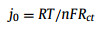
Huang et al. [159] directly synthesized Cu-MOF on the Cu foil surface using an in-situ growth technique and prepared Cu-MOF-30min and Cu-MOF-24h according to the different soaking times in the growth solution. SEM showed that Cu-MOF-30min had a smoother surface after cycling, indicating that Cu-MOF effectively induced uniform deposition of Li. The further electrochemical test showed that the battery with Cu-MOF-30min as the electrode had almost retained its capacity after 1-300 cycles of electroplating/stripping. In addition, Cu-MOF-30min had a smaller semicircle at high frequency in EIS, indicating a lower and more stable interface impedance, which was further quantitatively calculated using the formula of current density:
|
(1) |
where R represents the gas constant, T stands for the absolute temperature, n is the charge transfer number, F denotes the Faraday constant, and Rct represents the charge transfer impedance. The current density of Cu was calculated as j0 = 0.586 mA/cm2. The current densities of Cu-MOF-30min and Cu-MOF-24h in the electrolyte were calculated to be 0.635 and 0.165 mA/cm2, respectively. According to the magnitude of current density, Cu-MOF-30min provided a better force for electron diffusion.
Li et al. [160] designed two-dimensional MOF nanosheets OA-MOF using in-situ grown Cu-MOF as a precursor. In a half cell, at 3 mA/cm2 and 3 mAh/cm2, the Li@OA-MOF@Cu exhibited a hysteresis voltage of 68 mV and can stably cycle for 250 h. However, the overvoltage of the exposed Li electrode was 104 mV, and the short circuit caused by dendrites occurred at 130 h because the newly designed two-dimensional MOF nanosheet network provided sufficient nucleation points.
Carbonization technology can also improve the specific surface area of Cu-MOF. Wang et al. [161] prepared ordered three-dimensional structural material NC/Cu by carbonizing Cu-MOF synthesized on copper foil. After the carbonized composite was combined with Li, the symmetrical battery test showed that Li@NC/Cu||Li@ NC/Cu batteries could be charged and discharged up to 200 times at 0.5 mA/cm2@2 mAh/cm2. The CE of the batteries with the composite was 97%. In contrast, after 25 charging and discharging cycles, the CE of batteries with bare Li electrodes decreased. The decrease in the CE of the batteries was because the great specific surface area and rich porosity of NC/Cu reduced the influence of local current, thereby suppressing the probability of dendritic production.
Furthermore, Deng et al. [162] synthesized PPHK by adding polypyrrole (PPy) to HKUST-1. The resulting composite was combined with Li to protect the battery anode (Fig. 7a). To evaluate the performance, tests were conducted in a half cell at 5 mA/cm2. The results showed that Li@PPHK@Cu had a CE of 95.3% (over 80 cycles), and bare Cu was almost unable to work. The deposition behavior of Li on Cu and PPHK@Cu electrodes at different capacities was monitored by SEM (Fig. 7b). The results showed that PPHK effectively guided the deposition behavior of Li, resulting in a uniform distribution of Li on the electrode surface. At a rate of 1 C, the entire battery was assembled using LFP as the cathode. The initial specific capacity of Li@PPHK@Cu was 147.2 mAh/g. After 800 cycles, the capacity of Li@PPHK@Cu was 127.5 mAh/g with a CE of 99.8% (Fig. 7c). The excellent performance of Li@PPHK@Cu was because PPHK contained numerous lithophilic functional groups, which reduced the barrier of nucleation and successfully induced the uniform deposition of lithium on the electrode surface, effectively reducing the risk of dendrites.

|
Download:
|
| Fig. 7. (a) Schematic diagram of PPHK@Cu structure and synergistic effect on Li+. (b) SEM images of Cu and PPHK electrodes electroplating/stripping. (i-iii) The deposition of Li on Cu electrodes with capacities of 2, 5, and 10 mAh/cm2, respectively. (iv) Cu electrode after discharge at a capacity of 10 mAh/cm2. (v-vii) The deposition of Li on PPHK@Cu electrodes with capacities of 2, 5, and 10 mAh/cm2. (viii) PPHK@Cu electrode after discharge at a capacity of 10 mAh/cm2. (c) Tests conducted on Cu and PPHK@Cu electrodes in a full cell at 1 C. Copied with permission [162]. Copyright 2022, Wiley. | |
Unlike other metal bases, Cu-MOF is usually synthesized via in-situ growth methods, so the surface of copper foil can be directly constructed to provide green channels for Li+ shuttling. Moreover, the introduction of different functional groups in Cu-MOFs on Cu foil reduces the energy required for the nucleation site of Li and improves the affinity for Li, thus forming a uniform Li metal layer in the cycle process. In addition, the large void in the Cu-MOF structure also provides an ideal space for Li storage.
3.1.4. Other metal-based MOFs and their derivativesOther metal-based MOFs, such as Al-MOFs, Zr-MOFs, and Ni-MOFs, have been applied to the anode interface in Li batteries.
In 2019, Sun et al. [132] prepared a highly conductive composite material called Al2O3@MOF-C using Al-MOF as a precursor through the thermal decomposition method. In testing, the combination of Al2O3@MOF-C and lithium better demonstrated the composite as a promising electrode material. At 2 and 5 mA/cm2, the cell life was extended to 250 and 70 h, respectively. Moreover, at 2 mA/cm2, the hysteresis voltage of the composite electrode material was approximately 50 mV. Under the same condition, the lifespan of the Li@Cu electrode was significantly shorter than that of the Al2O3@MOF-C electrode, and it had a higher hysteresis voltage. The improved lifespan of Al2O3@MOF-C was because Al2O3@MOF-C had a large specific surface area and large pore size distribution ratio and contained Al2O3 as a nanocrystalline seed for lithium nucleation. The above result showed that Al2O3@MOF-C successfully induced uniform deposition of lithium. In 2022, Ma et al. [163] carbonized the product activity of Al-MOF combined with carbon nanotubes (CNTs) to produce a new material called Al-PCR/CNT. Al-PCR/CNT was combined with Li metal to form a composite anode. At 1 mA/cm2 and 4 mAh/cm2, SEM showed that dendrites appeared on the surface of the bare Cu electrode after 10 cycles, but no dendrites were observed on the Al-PCR/CNT- protected anode surface, indicating that a great specific surface area of Al-PCR/CNT made a huge contribution to the improvement of battery performance.
In 2020, Zhang et al. [164] successfully coated MOF-801 with Zr as the central element on lithium metal anodes. They found that Li@MOF-801 had a longer lifespan and more stable voltage than bare Li owing to the MOF-801-protected surface of the electrode. In addition, no Li dendrites formed on the Li@MOF-801 anode surface, while dendrites were formed on the exposed Li surface. Further analysis showed that the huge specific surface area and porous configuration of MOF-801 contributed to uniform Li+ flow and reduced the formation of dendrites.
Wu et al. [165] synthesized Ni-MOF-74/CNT with Ni as the central element and combined the resultant composite with lithium through solvent heating. Ni-MOF-74/CNT cycled for 900 h in a symmetrical battery at 5 mA/cm2 and 1 mAh/cm2. To explore the influence of Ni-MOF-74/CNT on batteries, it was further assembled with a Li-S full battery. At the rate of 0.2 C, the battery capacity increased to 1279 mA/g with a retention rate of 90% after 100 cycles. The enhanced capacity was because the special vertical structure of Ni-MOF-74/CNT generated active sites, which facilitated the transport of lithium, thus reducing the emergence of dendrites.
Zheng et al. [166] used Bi-MOF as a precursor to synthesize small cluster CF@BOC material (Fig. 8a). The binding energies of Li with graphene, Bi2 and Bi3 were calculated to be 0.46, −3.18 and −3.67 eV, respectively. The addition of Bi element on the surface can improve the lithium affinity of the electrode (Fig. 8b). After the Li was combined with CF@BOC, the CE of the electrode remained above 99.7% at 2 mA/cm2 after 520 electroplating/stripping cycles during the half-battery testing (Fig. 8c). However, batteries with lithium foil as the anode only cycled a dozen times before failure. Further exploration throughout the entire battery showed that CF@BOC@Li||LFP exhibited higher stability than bare Li at rates of 0.5, 1, 2, and 5 C (Fig. 8d). After 500 cycles at 1 C, the CF@BOC@Li||LFP battery showed better stability and higher capacity at a retention rate of 86.7%, while the Li||LFP battery had a capacity retention rate of only 63.6%. The small clusters are unique to CF@BOC and can be widely distributed on the anode surface, thus effectively inducing uniform deposition of Li on the surface and reducing the possibility of dendrite formation.

|
Download:
|
| Fig. 8. (a) The preparation procedure of CF@BOC@Li. (b) Li binding energy with graphene, Bi2 and Bi3 respectively calculated by DFT. (c) Coulombic efficiency of batteries at a current density of 5 mA/cm2 and a capacity of 1 mAh/cm2. (d) Rate performance testing of full batteries. Copied with permission [166]. Copyright 2023, Elsevier. | |
For the metal anode protective layer, it is very important to maintain a stable morphology during the plating/stripping process. The stable morphology enables that the protective layer has a long-lasting inhibitory effect on the growth of dendrites, in other words, the battery can have a longer service life. Interestingly, MOFs have been proved to own stable spatial structure and can function as protective materials for metal anodes. Zhang et al. [133] examined the morphology of MOF-coated Li anode after 50 cycles by SEM technique. It was found that Zn-MOF remained original and uniformly distributed on the electrode surface during the plating/stripping process. This implied that Zn-MOF performed well in protecting the anode with the benefit of its own structural stability. Similarly, Deng et al. [162] detected structure information about MOFs during the charging/discharging process. After in situ XRD characterization of the anode, it was found that the diffraction peak of HKUST-1 did not disappear. This finding suggested that HKUST-1 showed stable electrochemical properties, which could well protect the metal anode during the repeated cycling process. In addition, Wu et al. [165] also found that there was no significant morphological change for Ni-MOF-74 after cycling. It can be concluded that MOFs exhibit excellent electrochemical and structural stability during repeated plating/stripping processes, thus enabling MOFs to play a vital role in protecting anode. However, it is worth noticing that the structure of MOFs becomes not so stable in extreme acid-base or oxidizing environments.
In addition, the uneven distribution of current on the anode surface leads to an increase in resistance and a loss of power, which reduces the actual output current. The increase in the specific surface area of MOFs has a positive effect on the suppression of the hazards posed by localized current. However, an excessively large specific surface area may reduce the performance of the cell due to the increased contact area with the electrolyte, which makes it easier for the active substances in the solvent to occupy the active sites on the anode surface, hindering the passage of metal ions. For instance, Guo et al. [167] composited MOF-808 with hollow carbon fiber (HCF) to obtain MOF-HCF. After testing the battery performance, it was found that the MOF-808 with excessively specific surface area exhibited poorer performance than the MOF-HCF. This was due to the side reaction between the MOF-808 and the electrolyte that hinders the passage of Li+. Sometimes, the increase in specific surface area of MOFs was negatively correlated with the retention of CE. For example, ZIF-8 obtained using different doses of methanol solution was carbonized to obtain the products h-ZNCC (1153 g/m2) and ZNCC (398.7 g/m2). At a rate of 1 C, they had CE of 84.2% and 89.2%, respectively [139]. This may be due to the excessively large surface area of h-ZNCC, which requires more Li+ to form SEI.
Monometallic MOFs were selected based on their strong affinity for Li metal. The high-affinity central element can effectively decrease the nucleation potential of Li+. Thus, Li can be uniformly deposited on the electrode surface, thus effectively restraining the formation of dendrites and improving the battery life and capacity.
3.2. Protection by bimetallic MOFs and their derivativesCommon lithophilic materials can efficaciously induce the uniform deposition of Li, such as metal oxides (ZnO) and metal nanoparticles (Ag, Zn). However, these common lithophilic materials are formed by loosing accumulated units, resulting in poor mechanical strength of their structures. This type of lithophilic material is highly susceptible to damage after frequent and prolonged cycling. Therefore, researchers are conceptualizing a nanomaterial that can maintain structural stability while improving its lithophilicity. Based on this concept, researchers have found that carbonized ZIF-8 can effectively improve the lithophilicity of the material. In addition, carbonized ZIF-67 has a stable nanostructure that cannot collapse after multiple cycles. Therefore, researchers attempted to wrap the carbonized ZIF-8 onto the surface of the carbonized ZIF-67, forming bimetallic MOFs.
In 2022, Xu et al. [168] wrapped ZIF-8 with a layer of ZIF-67 and carbonized the composite at 600 ℃ to produce a carbon nanotube interwoven polyhedron (CNIP), which was compounded with Li to obtain Li@CNIP. At 3 mA/cm2, Li@CNIP worked for 1500 h, while Li@Cu only worked for 150 h. The testing and analysis results manifested that the high specific surface area of CNIP improved the performance of batteries. Similarly, Ma et al. [169] obtained Co@Zn-CNT composite material by carbonizing ZIF-8 surrounded by ZIF-67 and then combined with Li. To explore the function of Co@Zn-CNT, half cells were separately assembled with Co@Zn-CNT, Co-CNT-1h@Cu, and bare Cu electrodes. The nuclear potential of Co@Zn-CNT was lower than 7 mV, which was much lower than those of Co-CNT-1h@Cu (23 mV) and bare Cu (37 mV). At 5 mA/cm2 and 5 mAh/cm2, Co@Zn-CNT stably cycled for 500 h. SEM analysis showed that the surface of Co@Zn-CNT was smooth at 10 mAh/cm2. However, a great number of dendrites were formed on the exposed electrode surface. The smooth surface of Co@Zn-CNT was form because Zn with lithophilicity could effectively regulate the Li+ flow and ensured the uniform distribution of Li on the surface of Co@Zn-CNT.
Both Zn and Co have an obvious affinity for Li, and the simultaneous action of these two elements on the Li metal can reduce the energy required for the deposition of Li+ and induce uniform deposition of Li+ to prevent dendrite growth. In addition, Zn and Co can facilitate the transport of lithium ions and make the voltage of the battery more stable. Bimetallic MOFs are promising materials for protecting battery anode.
Monometallic MOFs can be synthesized by simple, versatile and high-yield methods. Furthermore, the richness and diversity of monometallic MOFs can provide a variety of strategies for solving different problems about batteries. Despite the above advantages of monometallic MOFs, the mechanical structure of monometallic MOFs may be easily damaged. To solve the structural rigidity problem while remaining the lithophilicity, it is necessary to introduce a second metal element. For example, some bimetallic MOFs are centered on Zn and Co. The presence of Zn element greatly ensures that the materials have excellent affinity for lithium. Moreover, the doping of Co element effectively contributes to the stabilization of the carbon skeleton structure in the MOFs. In addition, the differences in the coordination modes of Zn and Co provide a bicontinuous channel for Li+, which promotes the effective and rapid migration of Li+.
The carbonization process is a simple method for the synthesis of MOF derivatives. In the carbonized derivatives of MOFs, there are some substances that benefit the enhancement of battery performance. For example, ZIFs release N-containing groups and amorphous carbon during the carbonization process. The synergistic effect of N-containing groups and amorphous carbon enhances the conductivity of the material and reduces the nucleation barrier of metal ions. Nevertheless, in the carbonization process, collapse and irreversible aggregation of the carbon structure would happen, which leads to blockage of the channels. Using carbon derivatives as the anode interface protection layer, the diffusion of metal ions may be impaired during battery operation, failing to replenish metal ions on the anode surface promptly. Moreover, the carbonization also affects the pore size of MOFs. It is necessary to regulate the pore size of carbonized MOFs by some methods such as controlling temperature. For instance, Zhang et al. [170] controlled the pore size of MOF-5 derivatives by controlling the temperature and residence time. The percentage of large pores (> 10 nm) of the derivatives was higher when kept at 500 ℃ and 570 ℃ for 0.5 h. When the time was extended to 2 h, the number of small (< 1 nm) and medium pores (1-10 nm) pores increased, but the number of large pores decreases. When the time grew to 4 h, the number of medium pores of the derivatives at 570 ℃ increased and the ratio of small and large pores decreased. After the temperature rose to 700 ℃, the number of derivative pores was greater than that at low temperatures. Therefore, the pore size of the derivatives can be effectively and simply regulated by controlling the temperature and time. In addition, solvent molecules were easily deoxygenated at low voltages, leading to the formation of an unfavorable solid electrolyte interface layer on the anode surface and accelerating anode degradation [171]. By using MOFs with suitable pore sizes, it is possible to screen out unwanted/undesired materials or components, achieving to the purpose of protecting the anode [172].
In summary, the protective effect of MOFs and their derivatives on Li anodes can be mainly categorized into the synergistic effect among three parts: the central metal element, the abundant functional groups and the pore size.
The central metal element of MOFs can provide more negative charge for the nucleation of Li thus increasing the reaction dynamics. For Zn metal atoms, as the adsorption energy of Zn to Li was much lower than that required for C to Li and Cu to Li, Zn metal helped to reduce the energy required for Li nucleation [145]. In addition, the charge density difference of Li during the embedding process can be calculated by DFT. The results showed that Li underwent electron transfer near the carbon atom and exhibited a positive charge density [136]. Moreover, the negative charge would only partially migrate under polarized conditions, which made Li nucleation difficult. The involvement of Zn provided more charge, so that the charge around Li became sufficient prompting the redistribution of charge. This alleviated the problem of lack and uneven distribution of charge present in amorphous carbon structures. Similarly, the adsorption energy of Co with Li (−0.83 eV) was lower than that of copper foil with Li (−0.51 eV) due to the formation of unsaturated coordination bonds during coordination of Co [149]. The unsaturated coordination bonds were known to attract TFSI− ions in the electrolyte through the Lewis acid-base theory. In addition, it was demonstrated by DFT and finite element method (FEM) simulations that the unsaturated coordination bonds had a lower adsorption energy (−1.02 eV) with anions in the electrolyte [148]. The immobilization of anions led to a smoother migration of Li+, which was beneficial to replenish the Li+ concentration on the anode surface to make Li+ uniformly distributed and further form a homogeneous deposition. The oxidized clusters of Cu can provide more nucleation sites for the deposition of Li, which lead to the uniform deposition of Li on the anode surface [161]. Moreover, Al oxides can be viewed as a kind of nano-seeds during the nucleation of Li [132]. The Al-Li alloy formed during this period can effectively inhibit the appearance of dendrites. Thus, the central metal element of MOFs plays a decisive role in the Li metal protection.
In addition, among the many functional groups, the contribution of N-containing functional groups to Li deposition is not negligible. This is due to the fact that the involvement of N favors the enhancement of electrical conductivity. The adsorption energies of pyrrole N (N-5), pyridine N (N-6), and graphite N (N-Q) with Li were calculated to be −0.86, −1.08, and −0.62 eV, respectively. N-5 and N-6 exhibited higher lithophilicity, which could help to reduce the potential barrier for Li nucleation [148]. Moreover, for N-5 analogs the activated lone pair of electrons in the p-orbital could form Lewis basic sites [142]. This was fatal temptation for lithium ions, thus increasing the rate of Li+ migration. In addition, polar functional groups provided another viable option for the protection of Li metal anodes [147]. The evenly distributed polar functional groups provided more lithophilic sites for uniform deposition of Li on the anode surface.
The highly ordered pores of MOFs can effectively avoid Li+ enrichment on the anode surface and make Li+ uniformly distributed in the anode space [162]. In addition, the pore size is able to screen ions from the anode surface. The contact of unwanted ions/components with the anode is isolated to extend the life of the electrode and improve the battery performance.
Therefore, it is an effective strategy to utilize the high performance of MOFs to solve the problem of cell performance degradation caused by dendrites in LMB cells. However, the following issues should be fully considered when selecting MOFs:
(1) When selecting MOFs, it is necessary to consider the issue of the affinity of the substrate to Li. For substrates lacking lithophilic sites, such as carbon fiber networks and copper-metal foams, MOFs that can improve the lithophilicity should be selected. For example, it is possible to consider MOF with the Zn atom as the protective material for the anode. This is because the doping of Zn can provide more negative charge for Li deposition [136]. And Zn has lower adsorption energy with Li which can promotes the enhancement of the substrate’s Li-friendliness. In addition, MOFs containing abundant N-5 and N-6 can also enhance the affinity for Li [148].
(2) Similarly, the dynamics of Li ions at the anode surface is also one of the factors to be considered. In solid-state electrolytes, one of the causes of corrupted battery performance is the insufficient amount of Li+ on the anode surface due to lack of Li+ power. It is possible to choose MOFs that possess unsaturated coordination bonds to improve the above problem. For example, a large number of unsaturated ligand bonds in Co-MOFs exhibited strong binding ability to ligand TFSI− [148]. This provided the motivation for Li+ migration, which enabled the Li+ near anode surface to be replenished and redistributed evenly promptly. In addition, Cu-MOF showed stronger affinity and adsorption to the organic electrolyte. The super lubricity of Cu-MOF to the electrolyte reduced the impedance and favored the diffusion of Li+ [159].
(3) When selecting MOFs, the pore size should be considered to limit the entry of irrelevant particles onto the anode surface. In Li-S batteries, the pore size of MOFs should be considered at the first place. This is due to the fact that polysulfides are deposited on the anode surface to form an insulating layer that hinders the migration of Li+ [173]. For example, HKUST-1 had a maximum pore window of 0.9 nm, MOF-74 had a maximum pore window of 1.4 nm, and ZIF-8 had a pore size of only 0.38 nm [97]. An excessively large window would lead to the competition between Li+ and other ions in the migration, and reduced the Li+ power. A too small pore size would restrain the Li+ transportation, and the Li+ on the anode surface cannot be replenished quickly.
4. Na and K metal anodesNa metal anode is considered to be one of the most promising alternatives to Li metal anode because of its great theoretical energy density and low production cost [33–35]. Na-O2 has been partially commercialized and can be used in some microelectronic devices, such as cochlear implants and navigation lights. Similarly, PMBs have been explored because they have high specific capacity that can meet the development needs of today and are less expensive [42,43]. However, most of these batteries are disposable coins, and the safety risks caused by dendrites still restrict the development of SMBs and PMBs. Therefore, studying the protection of Na and K metals in batteries is highly desirable.
4.1. Protection by monometallic MOFs and their derivativesZIF-8 has been applied to protect Na metal anodes owing to its adjustable pore and large specific surface area. In 2022, Zhang et al. [174] synthesized a sandwich-like composite material ZIF-8-C@rGO using ZIF-8 as a precursor (Fig. 9a). The N-doped graphene (N-C) model was established to simulate the surface of ZIF-8. Na-Zn alloy (NaZn13) and Na2O represented the two final products of sodium binding with graphene and ZIF-8, respectively. The interface electron density difference calculated by DFT indicated that more electrons had been transferred between Na and Na2O on the same isosurface (Fig. 9b). This phenomenon showed that the addition of Zn element effectively improves the affinity between the electrode and sodium, contributing to the uniform deposition of Na. Then, the composite electrodes were made by depositing sodium metal onto the surface of ZIF-8-C@rGO. To evaluate the performance of ZIF-8-C@rGO more intuitively, rGO was used as the control group. The voltage capacity curve revealed that the required nucleation potential for ZIF-8-C@rGO was only 3 mV, while that of rGO was 35 mV (Fig. 9c). The lower nucleation overpotential indicated that the material had a stronger affinity for Na, which reduced the energy barrier during the nucleation process. At 1 mA/cm2 and 5 mAh/cm2, ZIF-8-C@rGO composite material exhibited a more stable working voltage and longer working time than rGO. SEM analysis showed that the surface of ZIF-8-C@rGO was still smooth and flat after 200 cycles (Fig. 9d), while the surface of rGO was uneven. These phenomena indicated that composite material ZIF-8-C@rGO regulated the uniform deposition of Na+ products on the anode. Further analysis revealed that ZIF-8-C@rGO contained many N sites, providing a green channel for Na nucleation. Meanwhile, the great specific surface area of ZIF-8-C@rGO minimized the formation of dendrites.

|
Download:
|
| Fig. 9. (a) ZIF-8-C@rGO structure and mechanism of inducing Na deposition. (b) Electron density differences at the interface of Na/C, Na/N-C, Na/NaZn13, and Na/Na2O (cyan and yellow regions show the depletion and accumulation of electrons, respectively). (c) Voltage distribution and nucleation region of rGO and ZIF-8-C@rGO electrodes at 1 mA/cm2 and 1 mAh/cm2. (d) SEM image of electrode ZIF-8-C@rGO after 200 cycles. Copied with permission [174]. Copyright 2022, American Chemical Society Publications. | |
In 2022, Passerini et al. [175] constructed the framework Cu@C by transforming Cu-MOF. Na metal with a capacity of 6 mAh/cm2 was electroplated on the exposed Al electrode and Cu@C. SEM analysis of the three stages of Na deposition revealed that Cu@C made the Na deposition more uniform and the anode surface smoother. The analysis of Cu@C showed that the improved performance of battery Cu@C was attributed to the provision of numerous nucleation sites to induce uniform distribution of Na on the anode.
In 2021, Zhang et al. [176] used MOF derivatives containing Bi elements to modify Na metal anodes and ameliorate battery performance. The role of Na on three different electrodes of bare Cu, CC, and Bi-MOF-derived materials was explored. The result showed that the addition of the Bi element increased the affinity for Na. Therefore, at 1, 2, and 5 mAh/cm2, CC@Bi@C can effectively suppress the dendrite formation. In a symmetrical battery, the CC@Bi@C electrode maintained a steady CE of 99.85% over 400 cycles at 1 mA/cm2 and 1 mAh/cm2. On the contrary, the other two electrodes experienced severe fluctuations in CE in less than 200 cycles.
To produce K batteries, in 2021, Xu et al. [40] carbonized ZIF-67 containing cobalt in an N2 environment to obtain ZIF-67@PAN (Fig. 10a). Subsequently, the calculation results indicated that carbon and graphite nitrogen had higher binding energies with K, while pyrrole nitrogen, pyridine nitrogen, and Co metal exhibited lower binding energies with K atoms. The addition of Co and N on this surface effectively enhanced the interaction between K and the substrate, thereby facilitating the deposition of K (Fig. 10b). ZIF-67@PAN was used to cover the surface of metal K to form an anode electrode and explored the properties of the anode in a half cell. When the capacity increased to 1 mAh/cm2, the voltage fluctuation of the battery with bare K as the anode at 2 mA/cm2 was significant, and the battery life was less than 50 h. The battery with composited material ZIF-67@PAN as the anode had a more stable working voltage with a lifespan of 500 h (Fig. 10c). This performance of the battery owed to the high potassium affinity exhibited by ZIF-67@PAN, which effectively induced the even deposition of K on the electrode, reducing the formation of dendrites. Chen et al. [177] prepared CC@CuO by thermally decomposing Cu-MOF grown on CC and then infiltrated molten K into CC@CuO to prepare composite anodes. To better evaluate the performance of the CC@CuO@K electrode, CC@K and Cu foil were used as control electrodes. After 100 electroplating/stripping cycles, the hysteresis voltage of CC@CuO@K was significantly lower than that of CC@K and Cu foil in a half cell. At 0.5 mA/cm2 and 0.5 mAh/cm2, CC@CuO@K operated continuously for 1200 h, while CC@K and Cu foil had a lifespan of 300 h and 200 h, respectively. The improved lifespan of CC@CuO@K was because the huge specific surface area of CC@CuO effectively reduced the impact of local current density. In addition, the CC@CuO material provided more reaction sites for K deposition, improving its affinity for K. Based on the above discussion, CC@CuO can effectively induce uniform deposition of K.

|
Download:
|
| Fig. 10. (a) Preparation of Co-CNFs. (b) The calculated binding energy of K atom with (ⅰ) carbon, (ⅱ) graphitic nitrogen, (ⅲ) pyrrolic nitrogen, (ⅳ) pyridinic nitrogen, and (ⅴ) Co metal. (c) Cyclic testing of K and Co-CNF@K electrodes at a current density of 2 mA/cm2 and a capacity of 1 mAh/cm2. Copied with permission [40]. Copyright 2021, American Chemical Society Publications. | |
The MOFs with a single metal element are not randomly selected but are carefully considered and selected. They can act as protective materials for Na and K metal anodes owing to their good affinity for Na and K. The introduction of MOFs into the anode can improve the affinity of the original sodium and potassium anodes. MOF with good affinity can regulate the smooth deposition of Na+ and K+ on the anode, thereby reducing the energy barrier for Na and K nucleation. Therefore, Na and K can be uniformly deposited on the anode surface to reduce the risk of dendrites. In addition, the frame structure of MOF enables these metals to be smoothly distributed on the anode surface so that the adsorption of Na and K will not concentrate in some positions.
4.2. Protection by bimetallic MOFs and their derivativesSimilar to protection materials for Li metal anode, the affinity of monometallic MOFs to Na or K is limited. To improve the affinity, researchers introduce two kinds of metals into the protection material at the same time. In 2020, Kim et al. [178] introduced Zn and Ni elements with high affinity for Na into MOF materials, followed by carbonization to obtain porous carbon nanomaterials (PCNF) with fibrous shapes. In addition, the performance of PCNF was evaluated in half cells, and a CNF electrode was selected for comparison. At 1 mA/cm2@1 mAh/cm2, the battery almost retained its initial capacity under the protection of PCNFs. In more than 600 cycles, the CE of the PCNF-protected electrode was 99.8%. However, after 100 charging and discharging cycles of batteries equipped with exposed electrodes, its CE began to fluctuate like a mountain under the same charging and discharging conditions, and the loss of battery capacity was even more significant. The improved CE of the battery assembled with PCNF-protected electrode was because PCNFs contained a large amount of pyrrole N, which induced the even deposition of Na on the electrode surface.
The appearance of bimetallic MOF protective materials is a continuation of the monometallic MOFs. The selection of multiple elements with an affinity for Na and K to the MOF structure can play a different role in coating the Na and K metal anode. Therefore, the modification of bimetallic MOFs for sodium and potassium metal anode has a broad prospect.
In summary, MOFs with Zn, Co, and Cu as central elements show higher affinity for Na and K metal cells. DFT showed that carbonized Zn-MOF provided more nucleation sites for Na and K. Zn vacancies provided adsorption energies ranging from −4.11 eV to −3.9 eV when Na was embedded [38]. For K, Zn vacancies provided an adsorption energy of −5.12 eV when the first K was embedded. After a second K entered, K bonded not only to N but also to C atom. These results indicated that the affinity for Na and K was enhanced. In addition, Cu promoted the graphitization of C during carbonization to enhanced the conductivity of the material.
5. Multivalent metal (Zn, Mg) anodesIn large-scale storage applications, establishing a balance between safety and performance is always a challenge. Multivalent metal-based batteries, such as Zn and Mg metal batteries, have been considered promising metal batteries because of their advantages of non-flammability, low toxicity, and high theoretical capacity [179,180]. However, the multivalent metal ions suffer from a severe kinetic lag, which accelerates the formation of a strong concentration gradient close to the anode surface, resulting in dendrite formation and a short circuit inside the battery [181,182]. Therefore, to solve this problem, stable MOF materials can be used to construct dendrite-free multivalent metal-based anodes. There are two main methods of constructing dendrite-free multivalent metal-based anodes with low polarization potential and good cycling stability: (1) In-situ preparing the surface of the multivalent metal-based anode; (2) Combined modification with structural design strategies.
5.1. Zn-MOFs and their derivativesIn Zn and Mg metal cells, because the central atom of the Zn-MOF materials has the same valence as the anode material, many researchers have chosen to link the Zn-MOF materials directly to the divalent metal anode via in-situ crystallization, electroplating, or secondary growth crystallization without the use of binders.
In 2022, Cui et al. [131] constructed porous ZIF-8 layers on the Zn anode using an in-situ growth method (Fig. 11a). ZIF-8 material has a large specific surface area conducive for the electrolyte to better combine with the main anode material. They suggested that porous ZIF-8 layers constructed by in-situ growth could regulate the growth of zinc dendrites and inhibit the hydrogen evolution reaction (Fig. 11b). Therefore, the Zn@ZIF-8 anode exhibited the characteristics of low nuclear potential, uniform distribution of Zn2+ concentration, smooth zinc plating/stripping, and enhanced corrosion resistance of Zn (Figs. 11c and d). At 0.5 mA/cm2@0.2 mAh/cm2, Zn@ZIF-8 symmetrical batteries prolonged the battery cycle life to 680 h, which is 2.78 times that of bare zinc foil (Fig. 11e). SEM images of the electrode surface before and after the cycle (Figs. 11f-k) revealed that when the capacity increased from 1.0 mAh/cm2 to 10.0 mAh/cm2, smooth morphology was obtained. In addition, after 750 cycles (750 h), the CE of the symmetrical battery using Zn@ZIF-8 anode was 98.89%, which was significantly more durable and stable than the bare zinc anode.

|
Download:
|
| Fig. 11. (a) Schematic diagram of in situ growth method for constructing Zn@ZIF-8. (b) Schematic diagram of surface cycling process on bare Zn and Zn@ZIF-8 anode. SEM images of (c) bare zinc foil and (d) Zn@ZIF-8 anodes immersed in 2 mol/L ZnSO4 electrolyte for 24 h. (e) At 0.5 mA/cm2@0.2 mAh/cm2, the long-term cycling performances of bare zinc and Zn@ZIF-8 anode. (f-k) SEM images of Zn deposited on bare Zn foil and Zn@ZIF-8 anode for different capacities. Reproduced with permission [131]. Copyright 2022, Elsevier. | |
In 2022, Zhang et al. [53] constructed a ZIF-8@Mg composite material through electrodeposition and directly formed a large-area and defect-free ZIF-8 film on the surface of Mg. In a full battery, the bare Mg anode provided a discharge capacity of about 24 mAh/g in the first cycle at 29.4 mA/g. The formation of dendrites on the Mg anode prevented the Mg2+ cycle, decreasing the capacity of the cell to almost zero in the following cycle. In contrast, the initial capacity of the ZIF-8@Zn composite anode in the full cell was 44 mAh/g and reduced to approximately 34 mAh/g after 30 cycles. Therefore, the uncontrolled intergranular penetration and subsequent decomposition of solvent molecules were effectively inhibited by the protection of the ZIF-8 membrane, allowing stable intergranular movement of solvent molecules and uniform deposition of Mg.
In 2022, Wang et al. [125] used zinc foil as the metal donor and grew Zn-TCPP material on the Zn surface using the solvothermal method. With the aid of binder-free PVDF and other materials, they used the self-template method to precisely control the size and structure of the Zn-TCPP nanoarray sheet on bare zinc (Fig. 12a). The zincophilic MOF sheets achieved even Zn2+ pre-seeding and laterally deposited Zn onto Zn-TCPP nanosheets, resulting in a spatially controlled U-shaped Zn deposition that effectively eliminated the "tip effect". SEM images showed that Zn@Zn-TCPP had a flat and dense zinc morphology after 10 cycles at 5 mA/cm2 and 0.5 mAh/cm2, which was in sharp contrast to the numerous zinc dendrite structures deposited on the exposed zinc surfaces (Figs. 12b and c). Even at 5 mA/cm2 (0.5 mAh/cm2), the Zn@Zn-TCPP anode exhibited excellent cycle stability within 1880 h (Fig. 12d). Moreover, Zn@Zn-TCPP symmetric cells had a good performance and lower overpotential in the 0.2-10.0 mA/cm2 (Fig. 12e).

|
Download:
|
| Fig. 12. (a) Schematic diagram of U-shaped zinc deposition on Zn-TCPP nanoarray coated Zn substrate. SEM images after 10 cycles of (b) bare Zn and (c) Zn@Zn-TCPP at 5 mA/cm2 (0.5 mAh/cm2). (d) Cyclic performance of Zn @ Zn-TCPP and Zn-symmetric cells at 5 mA/cm2 and plating/stripping capacity of 0.5 mAh/cm2. (e) Rate performance of Zn@Zn-TCPP and Zn-symmetric batteries at current densities ranging from 0.2 mA/cm2 to 10.0 mA/cm2. Copied with permission [125]. Copyright 2022, Elsevier. | |
In 2022, Xue et al. [183] adopted a template-building approach similar to the above work in their study. They successfully designed and manufactured a new 3D-ZGC framework for zinc metal anode by assembling graphene and carbon nanotubes into a layered porous configuration. Then, the structure was modified with carbonized Zn-MOF. The frame was a porous structure with a huge specific surface area, which could endow the anode with unique superiorities, such as uniform electric field distribution, unimpeded ion transport mechanics, and adequate space for high Zn loading to ensure even zinc plating/zinc extraction and high recovery rate. In addition, experimental investigation and DFT calculations demonstrated that uniformly distributed zinc-friendly ZnO nanoclusters generated by Zn-MOF could decrease the overpotential and induce even Zn nucleation, thereby inhibiting dendrite formation and achieving unprecedented fast cycling rate and prolonged cycle lifetime.In 2023, Lu et al. [184] inhibited the passivation reaction on the anode surface and accelerated the migration of Zn ions by constructing amorphous ZIF-8 (A-ZIF-8). The nucleation overpotential of Zn was reduced from 65 mV to 32 mV. A symmetric cell with A-ZIF-8 as the protective layer can operate continuously for about 8000 h at 1 mA/cm2@1 mAh/cm2. It was owing to the fact that the dense amorphous ZIF-8 can afford isotropic pathways that reduced the impedance of ion transport.
In summary, Zn-MOFs and their derivatives are suitable for the synthesis of thin film MOFs in Zn and Mg metal batteries, showing better adsorption without adding adhesives and conductive agents, reducing the interface impedance of the anode, effectively inhibiting the dendrites formation, and allowing multivalent metal ions to be uniformly deposited according to the fixed template. In addition, Zn-MOFs reduce overpotential, thus maintaining a high CE of the battery after many cycles and prolonging the battery life.
5.2. Other metal-based MOFs and their derivativesIn addition to the above Zn metal-based MOFs, other meta-based MOFs are also widely used in multivalent metal-based (Zn, Mg) batteries, such as Zr-MOFs [127,185], Ti-MOFs [126,186], Cu-MOFs [187], and Mg-MOFs [188].
In 2019, Liu et al. [181] covered the zinc anode with a slight protective layer comprising UIO-66 and PVDF. After the analysis of the electrode surface before and after 200 cycles using SEM, they observed that the zinc metal anode coated with UIO-66 and PVDF maintained its original structure (Figs. 13a-f). The MOF particles impregnated with electrolytes were in good contact with the electrolyte and could be adjusted to uniform zinc plating, thus inhibiting dendrite formation. The coated zinc anode was stably charged and discharged without a short circuit at 7.5 mA/cm2. In addition, the coated zinc anode can cycle more than 500 times at 1 mA/cm2 or 3 mA/cm2, indicating stable cycling performances (Figs. 13g and h). By precisely controlling the current applied to the zinc electrode at the nanoscale interface, dendrite-free zinc anode can be formed.

|
Download:
|
| Fig. 13. SEM images of bare Zn foil (a) before cycling and (b, c) after cycling. SEM images of MOF@Zn foil (d) before cycling and (e, f) after cycling. Voltage profiles of galvanostatic Zn plating/stripping for different Zn electrodes at (g) 1 mA/cm2 and (h) 3 mA/cm2. Copied with permission [181]. Copyright 2019, American Chemical Society Publications. | |
The above study shows that zinc dendrites can be effectively inhibited by depositing a thin protective coating of UIO-66 and PVDF on the Zn anode, significantly reducing overpotential during the cycle, especially at higher rates. Kim et al. [127], Xu et al. [126], and Lei et al. [189] also achieved results.
In 2022, Kim et al. [127] added HFP to the composite protective layer comprising Zr-MOF-80 and PVDF adhesive. PVDF-HFP is a copolymer of hexafluoropropylene (HFP) and vinylidene fluoride (VDF). PVDF-HFP exhibits enhanced ionic conductivity and stronger binding affinity and lower overpotential than PVDF, and it can further improve the durability of the thin protective layer of Zr-MOF-80 [190,191]. At 240 mA/cm2, the voltage curve remained steady through 2400 cycles, confirming the importance of the durability role of the MOF protective layer. In 2022, Xu et al. [126] synthesized a Ti-MOF-derived TiO2/NC nanocomposite. They coated the nanocomposite on a zinc foil anode using an adhesive. The effects of TiO2/NC coating on anticorrosion, dendrite growth inhibition, and hydrogen precipitation reduction were verified via experiments, and the effects of TiO2 nanoparticles on Zn dendrite growth inhibition and H2 precipitation reduction in the NC matrix were theoretically studied. The Zn@TiO2/NC anode had a cycle life of over 1100 h with a CE of 99.4%, which was about five times that of the bare zinc anode. Zn@TiO2/NC anode showed good cyclic stability and hydrogen production inhibitory effect.
To meet the corresponding coating requirements, PVDF adhesives were used to paste powdery protective materials on the surface of multivalent metal anodes. However, powders are not the only choices.
In 2019, Luo et al. [188] used chemical methods to grow Mg-MOF-74 thin films on the surface of Mg metal. Their experimental result confirmed that the film had an insulating effect, facilitated the transport of Mg2+, and could effectively prevent the exchange of solvents and anions between the anode and cathode. At 0.05 mA/cm2 and overpotential below 0.3 V, the Mg-MOF-74@Mg metal battery prepared by the above method was successfully cycled more than 100 times. In 2022, Zou et al. [187] prepared SeCu-MOF@Zn by directly growing three-dimensional Cu-MOF on the Zn metal surface using the hydrothermal method and selenizing Cu-MOF@Zn anode (Fig. 14a). Compared with Cu-MOF@Zn, SeCu-MOF@Zn anodes made the deposition of Zn2+ more compact and uniform (Fig. 14b). SEM images of bare zinc, Cu-MOF@Zn, and SeCu-MOF@Zn were obtained after 20 cycles at 2.0 mA/cm2 (Figs. 14c-e). Among them, the bare zinc anode exhibited a lot of dendrites and volume expansion during the cycles (Fig. 14c). Cu-MOF@Zn gradually lost the ability of regulating Zn2+ deposition with the increase of cycle times (Fig. 14d). In contrast, SeCu-MOF@Zn was still discernible after cycling (Fig. 14e). The electrochemical properties of bare zinc, Cu-MOF@Zn, and SeCu-MOF@Zn in the half cell showed that the voltage of bare zinc suddenly dropped after 28 h of operation under a constant current cycle of 2.0 mA/cm2@1.0 mAh/cm2; Cu-MOF@Zn cycled for 150 h with an increase in voltage hysteresis phenomenon; SeCu-MOF@Zn had a cycle life of over 500 h (Fig. 14f). SeCu-MOF@Zn stably cycled for 300 h even at 10.0 mA/cm2 (Fig. 14g). The more uniformly the MOF material was deposited on the Zn anode surface, the more improved the cycle life and cycle rate can be achieved in the full cell.

|
Download:
|
| Fig. 14. (a) Diagram of synthesis method of SeCu-MOF@Zn. (b) Schematic diagram presenting the Zn deposition mode on bare Zn, Cu-MOF layer, and SeCu-MOF layer. (c-e) SEM images of bare Zn, Cu-MOF@Zn and SeCu-MOF@Zn after 20 cycles at 2.0 mA/cm2. (f) At 2.0 mA/cm2@1.0 mAh/cm2, the voltage profiles of bare Zn, Cu-MOF@Zn, and SeCu-MOF@Zn symmetric cells. (g) At 10.0 mA/cm2@1.0 mAh/cm2, the voltage profiles of bare Zn, Cu-MOF@Zn, and SeCu-MOF@Zn symmetric cells. Reproduced with permission [187]. Copyright 2022, American Chemical Society Publications. | |
In summary, the protective effects of MOFs and their derivatives on Zn and Mg anodes can be mainly divided into two aspects. (1) The central atom of MOFs. DFT evidenced the interaction between central atoms and multivalent metal ions Zn2+ or Mg2+, indicating that there was a strong affinity between the central atoms of MOFs and the metal ions. The diffusion clusters of hydrated metal ion would lose water molecules due to charge redistribution, promoting the metal ions to adsorb on the central metal of MOFs. (2) Highly ordered pore structure of MOFs. This structure can effectively suppress intergranular voids, providing superior solvent resistance and precise molecular/ion sieving of the Angstrom level in MOF channels. Therefore, the highly ordered pores of MOFs can play a stabilizing role in the metal anode during the repeated plating/stripping process [192,193]. This structure redistributes the metal ions uniformly near the anode surface, suppressing the growth of dendrites and improving the performance of multivalent metal-based batteries. Reports on the applications of MOFs to the anode interface on various metal anodes have been summarized in Table 1.
|
|
Table 1 Application of MOFs and their derivatives in metal anodes. |
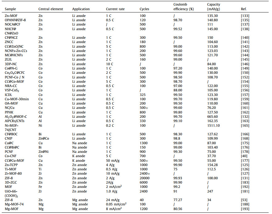
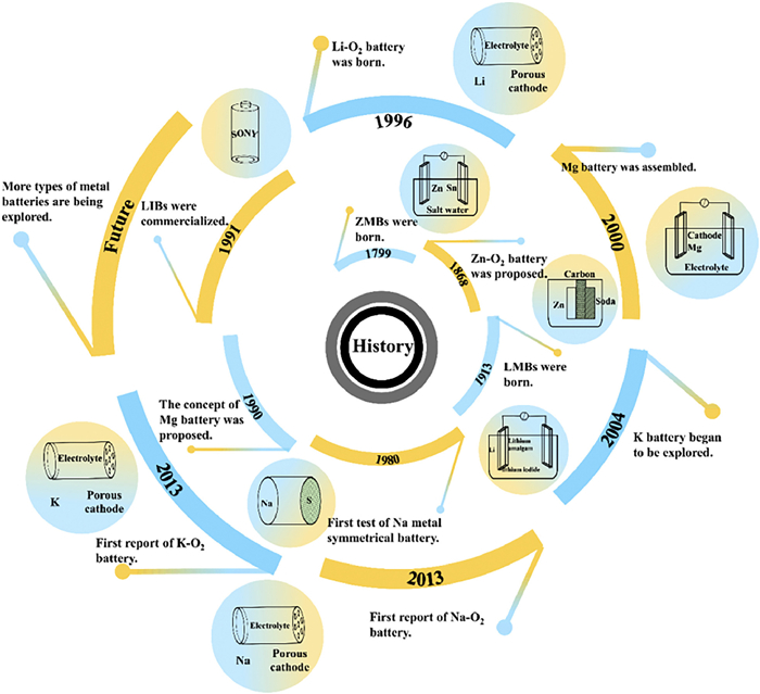
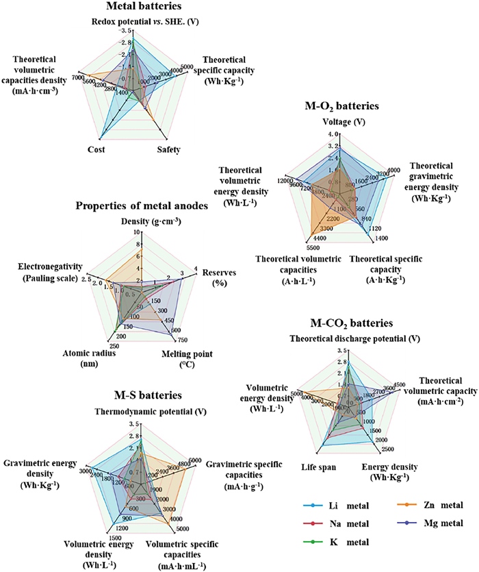
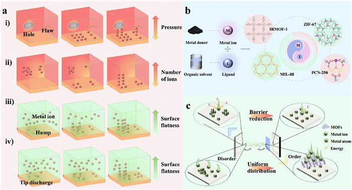
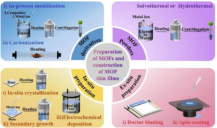
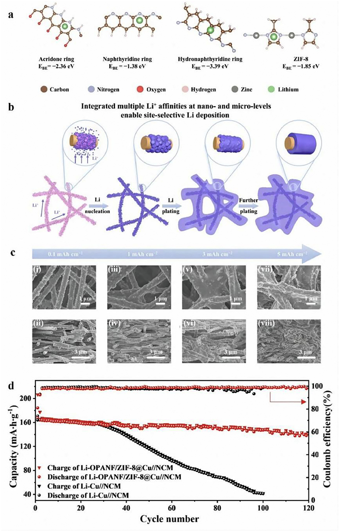
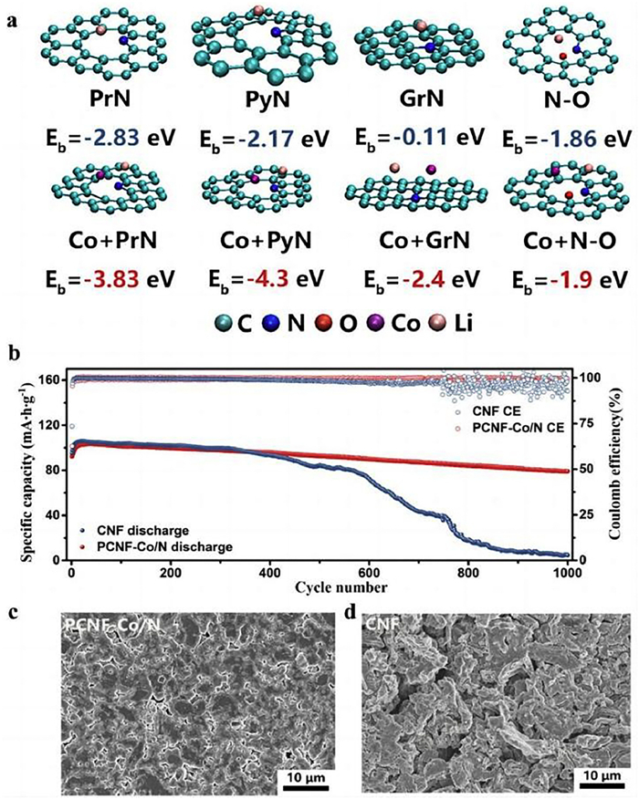
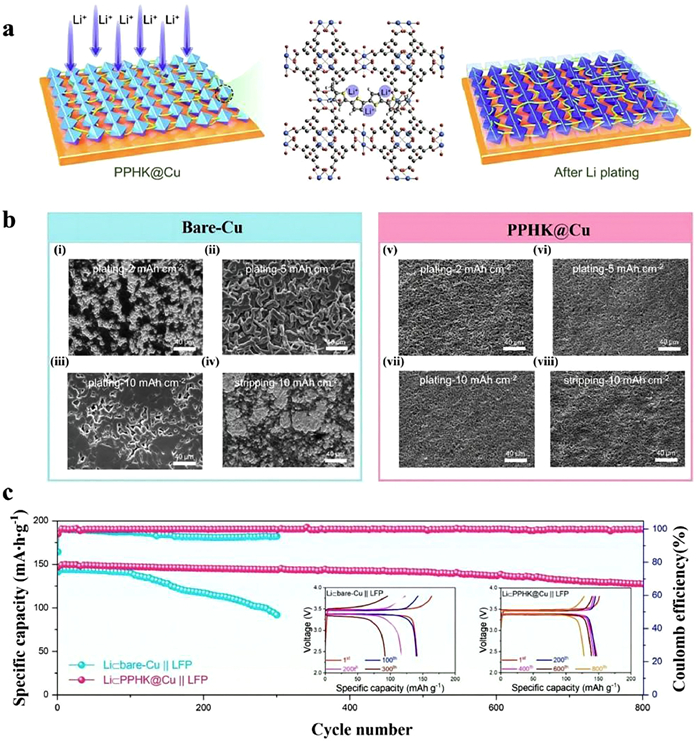
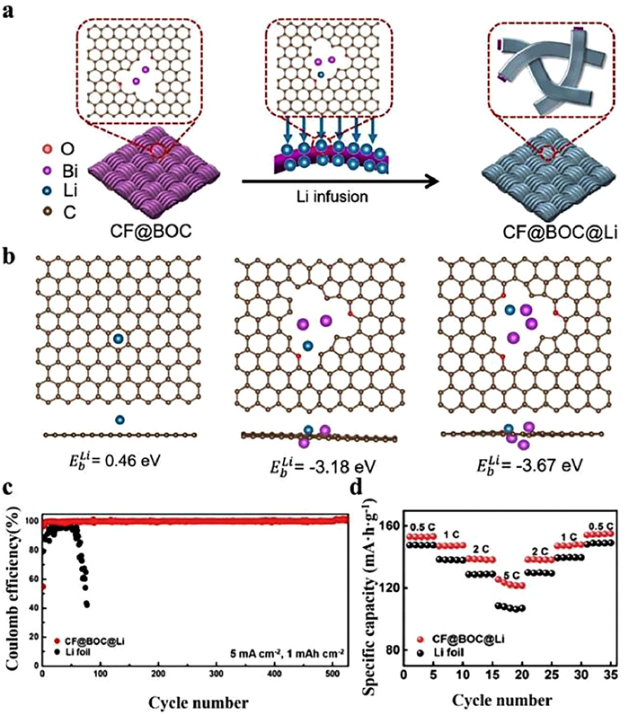
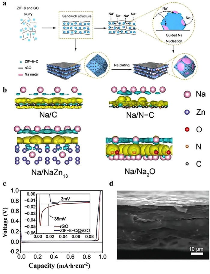
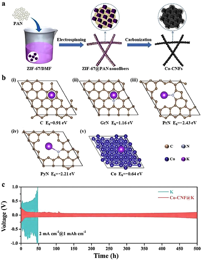
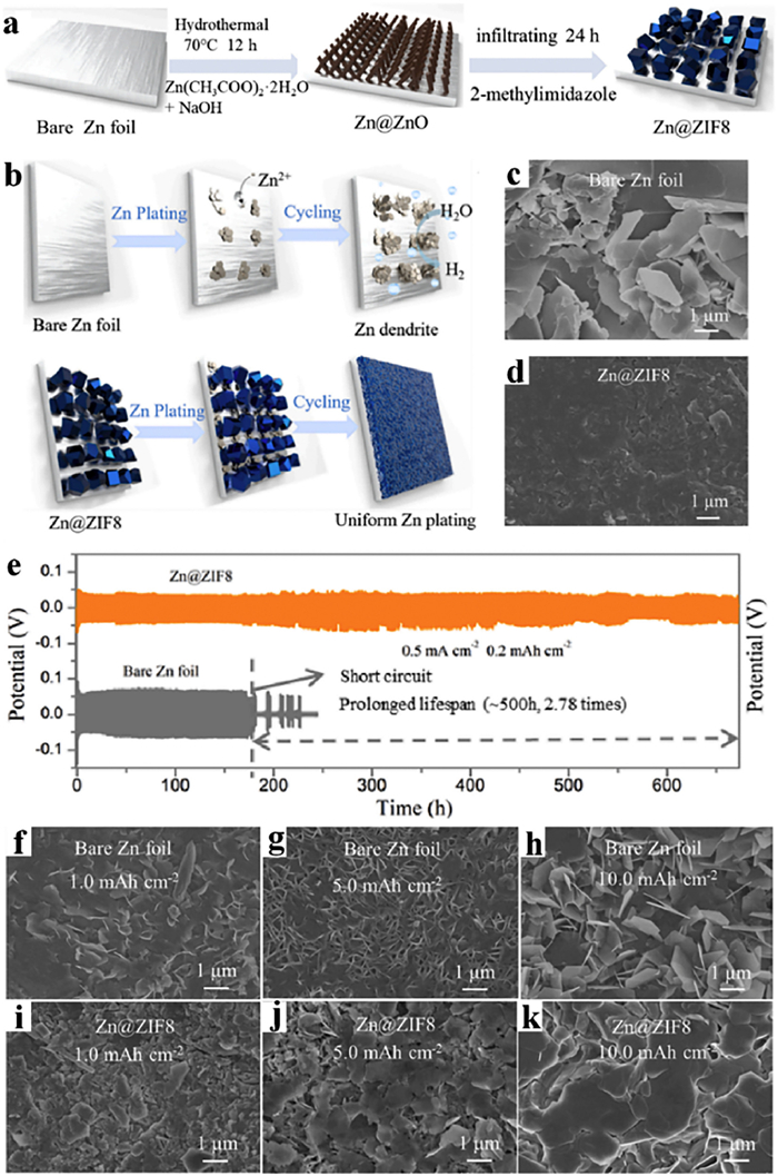
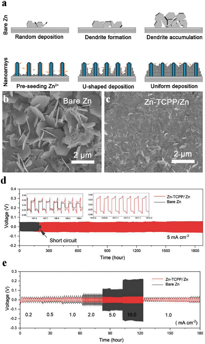
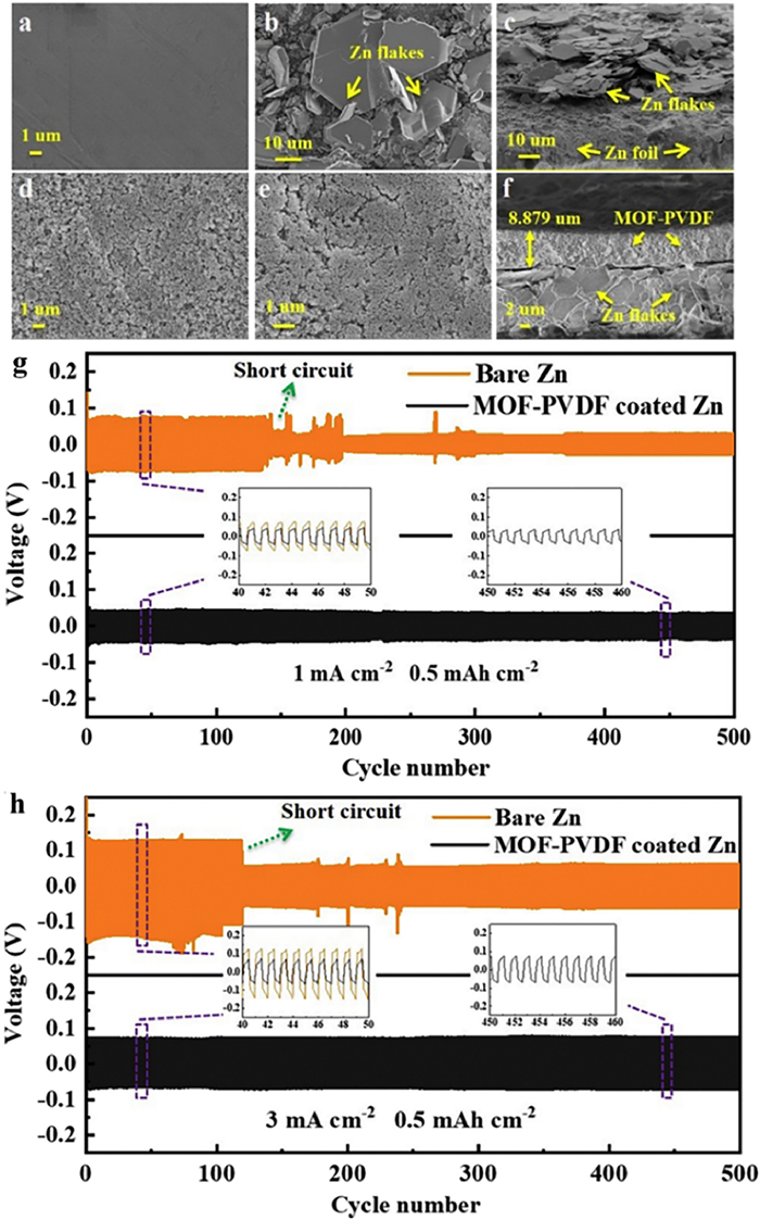
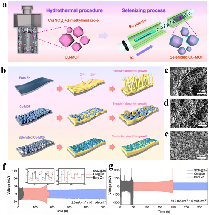
In this review, we discuss recent advances on the protection mechanisms of Zn-MOFs, Co-MOFs, Cu-MOFs as well as other monometallic MOFs and bimetallic MOFs on the anodes of Li, Na, K, and multivalent (Zn, Mg) metal batteries. The aim is to understand the challenges faced by anodes in metal batteries and thus to rationally construct protective materials to solve the problems faced by metal anodes in the cycling process. The metal anodes mainly face the following problems: (1) At the anode-electrolyte interface, the lack of affinity of the anode substrate for the metal elements leads to the inability of the metal elements to be uniformly deposited and nucleate on the anode surface, thus inducing the appearance of dendrites. (2) The metal ions in the electrolyte are surrounded by a large number of solvent molecules which can lead to slow metal ion migration. (3) The local current on the anode surface increases the ineffective consumption of power and weakens the actual current output.
Constructing MOF protective layers can be an effective way to address the challenges faced by metal anodes. (1) Metal elements and functional groups in MOFs can effectively improve the affinity of anode to metal elements. The central metal element can provide more negative charges, which helps to reduce the energy of metal ion nucleation. (2) According to Lewis acid-base theory, MOFs containing a large number of unsaturated coordination sites can adsorb anions in electrolytes, thus potentially increasing the metal ion transference number. Due to the timely replenishment of metal ions on the anode surface, the lifespan of the anode is extended. (3) The large specific surface area of MOFs can help to alleviate the impact of local currents and improve the output of actual currents (Fig. 15a).

|
Download:
|
| Fig. 15. (a) Design principles of MOF materials. (b) Future development of MOFs applied to anode interface. | |
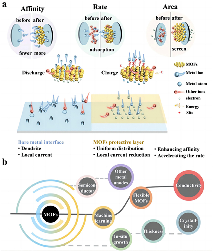
Despite the notable achievements of MOFs and their derivatives in protecting the anodes of metal batteries, MOFs and their derivatives still face many challenges, such as:
(1) Ex-situ coating and in situ growth are major assembly methods of MOFs on metal anodes. Each method has advantages and drawbacks. Ex-situ coating is versatile and it is easy to operate. However, it is difficult to ensure that the MOF layer on the anode surface is of the same thickness during lamination with the anode, which can lead to deviations in the experimental results. The effect of the thickness of the MOF layer on metal batteries performance is also an issue of concern. In addition, the use of adhesives may clog the aperture of MOFs and affect the migration of ions. In situ growth can effectively avoid the problem of blocking the channels. However, the in-situ growth method is not suitable for all anode materials and usually requires a complicated pretreatment process. Therefore, it is still necessary to find more concise and effective methods to assemble MOFs on anode materials.
(2) The lack of intrinsic electrical conductivity is a critical issue for MOFs themselves. At present, it is very common to enhance the conductivity of MOFs by carbonization process, which expands the specific surface area at the same time. The increased specific surface area helps to reduce the effect of localized currents and provide more nucleation sites, thus improving the cell performance. However, an excessive specific surface area would attract more electrolytes, and these adsorbed electrolytes would seize the active sites provided by the MOFs. This means that the deposition of metal ions would be difficult, and at the same time, the electrolyte would compete with the metal ions for priority use of the channel when occupying the active site. This could greatly reduce the migration rate of the metal ions. It is necessary to develop cost-effective means to increase the electrical conductivity of MOFs materials by introducing/altering functional groups or designing nanostructures.
(3) The crystallization degree affects the properties of MOF materials. However, there are few studies on the effects of the crystallization degree of MOFs as anode protection layer on metal batteries performance, which need to be further investigated.
(4) MOFs with the property of reversible structural transformation in response to external stimuli are called flexible MOFs, which can adjust their pore size according to guest molecules adsorption, temperature, mechanical pressure, and lighting irradiation. This kind of MOFs with "breathing" mode of operation is promising to control the metal ion migration in rechargeable metal batteries.
(5) The research on the protective effect of MOFs on metal anodes should not be limited to LMBs, SMBs, and ZMBs. The application of MOF materials to more metal anodes interface (such as K, Mg, Al, Fe, and Sn) has bright prospects. At present, most MOFs and their derivatives mainly exhibit better affinity for Li, Na, and Zn. Therefore, machine learning can be used to optimize metal components and introduce effective functional groups to construct novel MOFs with a better affinity for metals, such as K, Mg, and Fe. In addition, in the current era of developing novel energy devices, exploring the impact of combining MOF materials with newly developed semiconductor air battery anodes (Si and Ge) on battery performance also has broad prospects (Fig. 15b).
Declaration of competing interestThe authors declare that they have no known competing financial interests or personal relationships that could have appeared to influence the work reported in this paper.
AcknowledgmentsThe authors gratefully acknowledge financial support from the National Natural Science Foundation of China (No. 61904073), Spring City Plan-Special Program for Young Talents (No. K202005007), Yunnan Local Colleges Applied Basic Research Projects (Nos. 202101BA070001-138, 2018FH001-016), Yunnan Talents Support Plan for Yong Talents (No. XDYC-QNRC-2022-0482), Frontier Research Team of Kunming University 2023, and Yunnan Provincial Education Department (Nos. 2022Y732, 2022Y739).
| [1] |
J. Lin, X. Zhang, E. Fan, et al., Energy Environ. Sci. 16 (2023) 745. DOI:10.1039/D2EE03257K |
| [2] |
Y. Yu, S. Hu, Chin. Chem. Lett. 32 (2021) 3277-3287. DOI:10.1016/j.cclet.2021.04.049 |
| [3] |
Y. Zhang, S. Gao, T. Zhao, et al., Ara. J. Chem. 16 (2023) 105021. DOI:10.1016/j.arabjc.2023.105021 |
| [4] |
S. Waaijers-van der Loop, A. van Bruggen, N.R.M. Beijer, et al., Environ. Int. 160 (2022) 107055. DOI:10.1016/j.envint.2021.107055 |
| [5] |
D. Chen, X. Zhang, Y. Zhang, et al., Surf. Interfaces 284 (2023) 102777. |
| [6] |
C. Xu, P. Behrens, P. Gasper, et al., Nat. Commun. 14 (2023) 119. DOI:10.1038/s41467-022-35393-0 |
| [7] |
F. Maisel, C. Neef, F. Marscheider-Weidemann, N.F. Nissen, Resour. Conserv. Recy. 192 (2023) 106920. DOI:10.1016/j.resconrec.2023.106920 |
| [8] |
A. Rudola, R. Sayers, C.J. Wright, J. Barker, Nat. Energy 8 (2023) 215. DOI:10.1038/s41560-023-01215-w |
| [9] |
T. Zhao, Y. Zhang, D. Wang, et al., Carbon 205 (2023) 86. DOI:10.1016/j.carbon.2023.01.020 |
| [10] |
Y. Zhao, C. Yang, Y. Yu, Chin. Chem. Lett. 35 (2024) 108865. DOI:10.1016/j.cclet.2023.108865 |
| [11] |
K. Osmani, M. Alkhedher, M. Ramadan, et al., J. Clean. Prod. 389 (2023) 136024. DOI:10.1016/j.jclepro.2023.136024 |
| [12] |
Y. Zhang, T.T. Zuo, J. Popovic, et al., Mater. Today 33 (2020) 56. DOI:10.1016/j.mattod.2019.09.018 |
| [13] |
F. Arshad, J. Lin, N. Manurkar, et al., Resour. Conserv. Recycl. 180 (2022) 106164. DOI:10.1016/j.resconrec.2022.106164 |
| [14] |
W.Z. Huang, C.Z. Zhao, P. Wu, et al., Adv. Energy Mater. 12 (2022) 2201044. DOI:10.1002/aenm.202201044 |
| [15] |
S. Chen, S. Chen, D. Han, C.W. Bielawski, J. Geng, Chem. Eur. J. 28 (2022) e202201580. DOI:10.1002/chem.202201580 |
| [16] |
S. Wang, B. Peng, J. Lu, et al., Chem. Eur. J. 29 (2023) e202202380. DOI:10.1002/chem.202202380 |
| [17] |
Y. Wang, J. Wang, J. Nai, et al., Chin. Chem. Lett. 35 (2024) 108510. DOI:10.1016/j.cclet.2023.108510 |
| [18] |
G.N. Lewis, F.G. Keyes, J. Am. Chem. Soc. 35 (1913) 340. DOI:10.1021/ja02193a004 |
| [19] |
F. Deng, Y. Zhang, Y. Yu, Batteries 9 (2023) 13. |
| [20] |
M.S. Whittingham, Chem. Rev. 104 (2004) 4271. DOI:10.1021/cr020731c |
| [21] |
T. Ohzuku, R.J. Brodd, J. Power Sources 174 (2007) 449. DOI:10.1016/j.jpowsour.2007.06.154 |
| [22] |
Q. Wang, B. Liu, Y. Shen, et al., Adv. Sci. 8 (2021) e2101111. DOI:10.1002/advs.202101111 |
| [23] |
L. Li, S. Li, Y. Lu, Chem. Commun. 54 (2018) 6648. DOI:10.1039/C8CC02280A |
| [24] |
K. Chayambuka, G. Mulder, D.L. Danilov, P.H.L. Notten, Adv. Energy Mater. 10 (2020) 2001310. DOI:10.1002/aenm.202001310 |
| [25] |
N. Nakamura, S. Ahn, T. Momma, T. Osaka, J. Power Sources 558 (2023) 232566. DOI:10.1016/j.jpowsour.2022.232566 |
| [26] |
L. Zhao, Z. Hu, Z. Huang, et al., Adv. Energy Mater. 12 (2022) 2200990. DOI:10.1002/aenm.202200990 |
| [27] |
Q. Zhu, W. Li, J. Wu, et al., J. Power Sources 542 (2022) 231791. DOI:10.1016/j.jpowsour.2022.231791 |
| [28] |
W. Zhou, M. Chen, Y. Quan, et al., Chem. Eng. J. 457 (2023) 141328. DOI:10.1016/j.cej.2023.141328 |
| [29] |
C. Wei, L. Tan, Y. Zhang, et al., Energy Stor. Mater. 52 (2022) 299. |
| [30] |
J. Qiao, Z. Bao, L. Kong, et al., Chin. Chem. Lett. 34 (2023) 108318. DOI:10.1016/j.cclet.2023.108318 |
| [31] |
H. Su, H. Zhang, Z. Chen, et al., Chin. Chem. Lett. 34 (2023) 108640. DOI:10.1016/j.cclet.2023.108640 |
| [32] |
Q. Sun, L. Dai, T. Luo, et al., Carbon Energy 5 (2022) e276. |
| [33] |
J. Wu, C. Lin, Q. Liang, et al., InfoMat 4 (2022) e12288. DOI:10.1002/inf2.12288 |
| [34] |
J. Chen, Y. Peng, Y. Yin, et al., Energy Environ. Sci. 15 (2022) 3360. DOI:10.1039/D2EE01257J |
| [35] |
X. Wang, H. Wang, Adv. Powder Mater. 1 (2022) 100057. DOI:10.1016/j.apmate.2022.100057 |
| [36] |
Q. Wang, Q. Feng, Y. Lei, et al., Nat. Commun. 13 (2022) 3689. DOI:10.1038/s41467-022-31383-4 |
| [37] |
A. Rudola, A.J.R. Rennie, R. Heap, et al., J. Mater. Chem. A 9 (2021) 8279. DOI:10.1039/D1TA00376C |
| [38] |
Y. Yu, D. Wang, J. Luo, Y. Xiang, Colloids Surf. A 659 (2023) 130802. DOI:10.1016/j.colsurfa.2022.130802 |
| [39] |
J. Huang, Y. Zhu, Y. Feng, et al., Acta Phys. Chim. Sin. 38 (2022) 2208008. |
| [40] |
L. Wang, H. Wang, M. Cheng, et al., ACS Appl. Energy Mater. 4 (2021) 6245. DOI:10.1021/acsaem.1c01002 |
| [41] |
X. Yi, Y. Feng, A.M. Rao, et al., Adv. Mater. 35 (2023) 2302280. DOI:10.1002/adma.202302280 |
| [42] |
Y. Feng, A.M. Rao, J. Zhou, B. Lu, Adv. Mater. 35 (2023) 2300886. DOI:10.1002/adma.202300886 |
| [43] |
H. Ding, J. Wang, J. Zhou, C. Wang, B. Lu, Nat. Commun. 14 (2023) 2305. DOI:10.1038/s41467-023-38065-9 |
| [44] |
A. Duan, S. Luo, W. Sun, Chin. Chem. Lett. 35 (2024) 108337. DOI:10.1016/j.cclet.2023.108337 |
| [45] |
H. Yan, S. Li, H. Xu, et al., Adv. Energy Mater. 12 (2022) 2201599. DOI:10.1002/aenm.202201599 |
| [46] |
X. Ge, W. Zhang, F. Song, et al., Adv. Funct. Mater. 32 (2022) 2200429. DOI:10.1002/adfm.202200429 |
| [47] |
Z. Liu, X. Luo, L. Qin, G. Fang, S. Liang, Adv. Powder Mater. 1 (2022) 100011. DOI:10.1016/j.apmate.2021.10.002 |
| [48] |
M. Zhou, Y. Chen, G. Fang, S. Liang, Energy Stor. Mater. 45 (2022) 618. |
| [49] |
P. Jain, S. Raghav, A. Dhillon, D. Kumar, Zinc Batteries 11 (2020) 167. |
| [50] |
K. Feng, D. Wang, Y. Yu, Molecules 28 (2023) 2721. DOI:10.3390/molecules28062721 |
| [51] |
S. Guo, L. Qin, C. Hu, et al., Adv. Energy Mater. 12 (2022) 2200730. DOI:10.1002/aenm.202200730 |
| [52] |
M. Zhou, C. Fu, L. Qin, et al., Energy Stor. Mater. 52 (2022) 161. |
| [53] |
Y. Zhang, J. Li, W. Zhao, Adv. Mater. 34 (2022) e2108114. DOI:10.1002/adma.202108114 |
| [54] |
C. Zheng, Y. Lu, J. Su, et al., Small Methods 6 (2022) 2200667. DOI:10.1002/smtd.202200667 |
| [55] |
Y. Deng, J. Zheng, Q. Zhao, et al., Small 18 (2022) 2203409. DOI:10.1002/smll.202203409 |
| [56] |
G. Sun, Y. Wang, D. Yang, et al., Chin. Chem. Lett. 35 (2024) 108469. DOI:10.1016/j.cclet.2023.108469 |
| [57] |
J. Guo, J. Liu, Nanoscale Adv. 1 (2019) 2104. DOI:10.1039/C9NA00040B |
| [58] |
Y. Shen, Z. Pu, Y. Zhang, et al., J. Mater. Chem. A 10 (2022) 17199. DOI:10.1039/D2TA04797G |
| [59] |
H. Jiang, X. Lin, C. Wei, et al., Small 18 (2022) 2107637. DOI:10.1002/smll.202107637 |
| [60] |
D. Xie, Z.W. Wang, Z.Y. Gu, et al., Adv. Funct. Mater. 32 (2022) 2204066. DOI:10.1002/adfm.202204066 |
| [61] |
Z. Wang, J. Liu, M. Wang, et al., Nanoscale Adv. 2 (2020) 1828. DOI:10.1039/D0NA00174K |
| [62] |
W.L. Huang, N. Zhao, Z.J. Bi, et al., Mater. Today Nano 10 (2020) 100075. DOI:10.1016/j.mtnano.2020.100075 |
| [63] |
Y. Chen, Y. Jiang, S.-S. Chi, et al., J. Power Sources 521 (2022) 230921. DOI:10.1016/j.jpowsour.2021.230921 |
| [64] |
F. Zhao, Q. Sun, C. Yu, et al., ACS Energy Lett. 5 (2020) 1035. DOI:10.1021/acsenergylett.0c00207 |
| [65] |
W. Liu, P. Liu, D. Mitlin, Chem. Soc. Rev. 49 (2020) 7284. DOI:10.1039/D0CS00867B |
| [66] |
X. Zhang, A. Wang, X. Liu, J. Luo, Acc. Chem. Res. 52 (2019) 3223. DOI:10.1021/acs.accounts.9b00437 |
| [67] |
Y. Zhao, K. Zheng, X. Sun, Joule 2 (2018) 2583. DOI:10.1016/j.joule.2018.11.012 |
| [68] |
Z. Hou, B. Zhang, EcoMat 4 (2022) 12265. DOI:10.1002/eom2.12265 |
| [69] |
J. Liang, X. Li, Y. Zhao, et al., Adv. Energy Mater. 9 (2019) 1902125. DOI:10.1002/aenm.201902125 |
| [70] |
H. Ge, X. Feng, D. Liu, Y. Zhang, Nano Res. Energy 2 (2023) 9120039. DOI:10.26599/NRE.2023.9120039 |
| [71] |
H. Li, S. Guo, H. Zhou, Energy Stor. Mater. 56 (2023) 227. |
| [72] |
J. Zhu, X. Li, C. Wu, et al., Angew. Chem. Int. Ed. 60 (2021) 3781. DOI:10.1002/anie.202014265 |
| [73] |
Basappa R.Hongahally, T. Ito, T. Morimura, et al., J. Power Sources 363 (2017) 145. DOI:10.1016/j.jpowsour.2017.07.088 |
| [74] |
Z. Zhang, L. Zhang, Y. Liu, et al., ChemSusChem 11 (2018) 3774. DOI:10.1002/cssc.201801756 |
| [75] |
J. Li, Y. Li, J. Cheng, et al., Carbon 177 (2021) 52. DOI:10.1016/j.carbon.2021.01.159 |
| [76] |
Y. Song, L. Yang, W. Zhao, et al., Adv. Energy Mater. 9 (2019) 1900671. DOI:10.1002/aenm.201900671 |
| [77] |
D. Zeng, J. Yao, L. Zhang, et al., Nat. Commun. 13 (2022) 1909. DOI:10.1038/s41467-022-29596-8 |
| [78] |
J. Li, Y. Li, J. Cheng, et al., J. Power Sources 518 (2022) 230739. DOI:10.1016/j.jpowsour.2021.230739 |
| [79] |
Y. Liu, H. Su, M. Li, et al., J. Mater. Chem. A 9 (2021) 13531. DOI:10.1039/D1TA03343C |
| [80] |
J. Duan, L. Huang, T. Wang, et al., Adv. Funct. Mater. 30 (2020) 1908701. DOI:10.1002/adfm.201908701 |
| [81] |
S. Xiong, Y. Liu, P. Jankowski, et al., Adv. Funct. Mater. 30 (2020) 2001444. DOI:10.1002/adfm.202001444 |
| [82] |
Q. Yu, D. Han, Q. Lu, et al., ACS Appl. Mater. Interfaces 11 (2019) 9911. DOI:10.1021/acsami.8b20413 |
| [83] |
C. Wang, K.R. Adair, J. Liang, et al., Adv. Funct. Mater. 29 (2019) 1900392. DOI:10.1002/adfm.201900392 |
| [84] |
Y. Hu, Y. Zhong, L. Qi, H. Wang, Nano Res. 13 (2020) 3230. DOI:10.1007/s12274-020-2993-4 |
| [85] |
H. Liu, P. He, G. Wang, et al., Chem. Eng. J. 430 (2022) 132991. DOI:10.1016/j.cej.2021.132991 |
| [86] |
A. Wang, J. Li, M. Yi, et al., Energy Stor. Mater. 49 (2022) 246. |
| [87] |
B. Zhao, Y. Shi, J. Wu, et al., Chem. Eng. J. 429 (2022) 132411. DOI:10.1016/j.cej.2021.132411 |
| [88] |
V.V.K. Lanjapalli, F.J. Lin, S. Liou, et al., Electrochim. Acta 410 (2022) 139976. DOI:10.1016/j.electacta.2022.139976 |
| [89] |
C. Zu, J. Li, B. Cai, et al., J. Power Sources 555 (2023) 232336. DOI:10.1016/j.jpowsour.2022.232336 |
| [90] |
Y. Liu, T. Guo, Q. Liu, et al., Mater. Today Energy 28 (2022) 101056. DOI:10.1016/j.mtener.2022.101056 |
| [91] |
B. Cui, Y. Gao, X. Han, W. Hu, J. Mater. Sci. Technol. 117 (2022) 72. DOI:10.1016/j.jmst.2021.10.040 |
| [92] |
Y.J. Liu, R.Y. Fang, D. Mitlin, Tungsten 4 (2022) 316. DOI:10.1007/s42864-022-00183-0 |
| [93] |
J.M. Kim, M.H. Engelhard, B. Lu, et al., Adv. Funct. Mater. 32 (2022) 2207172. DOI:10.1002/adfm.202207172 |
| [94] |
M. Liu, J. Cai, J. Xu, et al., Small 18 (2022) 2201443. DOI:10.1002/smll.202201443 |
| [95] |
J. Wang, Z. Zhao, F. Hu, et al., Chem. Eng. J. 451 (2023) 139058. DOI:10.1016/j.cej.2022.139058 |
| [96] |
W. Liu, J. Liu, Sci. Bull. 67 (2022) 1732. DOI:10.1016/j.scib.2022.08.006 |
| [97] |
X. Zhang, P. Dong, M. Song, Batteries Supercaps 2 (2019) 591. DOI:10.1002/batt.201900012 |
| [98] |
T. Wang, X. Zhang, N. Yuan, C. Sun, Chem. Eng. J 451 (2023) 138819. DOI:10.1016/j.cej.2022.138819 |
| [99] |
L. Tu, Z. Zhang, Z. Zhao, et al., Angew. Chem. Int. Ed. 62 (2023) e202306325. DOI:10.1002/anie.202306325 |
| [100] |
C. Li, L. Liang, X. Liu, et al., Carbon Energy 5 (2022) e301. |
| [101] |
Y. Zhao, K. Feng, Y. Yu, Adv. Sci. (2023) 2308087. |
| [102] |
C. Wei, L. Tan, Y. Zhang, S. Xiong, J. Feng, ChemPhysMater 1 (2022) 252. DOI:10.1016/j.chphma.2021.09.003 |
| [103] |
Q. Man, Y. An, C. Liu, et al., J. Energy Chem. 76 (2023) 576. DOI:10.1016/j.jechem.2022.09.020 |
| [104] |
Y. An, Y. Tian, H. Shen, et al., Energy Environ. Sci. 16 (2023) 4191. DOI:10.1039/D3EE01841E |
| [105] |
A. Parkash, N. Solangi, S. Solangi, S. Almani, S.A. Soomro, J. Electrochem. Soc. 169 (2022) 054504. DOI:10.1149/1945-7111/ac6985 |
| [106] |
R.A. Shaukat, Q.M. Saqib, J. Kim, et al., Nano Energy 96 (2022) 107128. DOI:10.1016/j.nanoen.2022.107128 |
| [107] |
V. Siva, A. Murugan, A. Shameem, S. Thangarasu, S.A. Bahadur, J. Inorg. Organomet. P. 32 (2022) 4707. DOI:10.1007/s10904-022-02475-x |
| [108] |
L. Chen, F. Yang, RSC Adv. 13 (2023) 808. DOI:10.1039/D2RA07209B |
| [109] |
H. Zhang, X. Hu, T. Li, et al., J. Hazard. Mater. 429 (2022) 128271. DOI:10.1016/j.jhazmat.2022.128271 |
| [110] |
H. Du, X. Gao, Q. Ma, X. Yang, T.S. Zhao, ACS Omega 7 (2022) 16826. |
| [111] |
M. Ma, X. Lu, Y. Guo, L. Wang, X. Liang, Trends Anal. Chem. 157 (2022) 116741. DOI:10.1016/j.trac.2022.116741 |
| [112] |
Y. Du, X. Gao, S. Li, L. Wang, B. Wang, Chin. Chem. Lett. 31 (2020) 609. DOI:10.1016/j.cclet.2019.06.013 |
| [113] |
W. Xin, J. Xiao, J. Li, et al., Energy Stor. Mater. 56 (2023) 76. |
| [114] |
H. Yang, C. Guo, A. Naveed, et al., Energy Stor. Mater. 14 (2018) 199. |
| [115] |
Z. Jiang, A. Li, C. Meng, X. Chen, H. Song, Phys. Chem. Chem. Phys. 24 (2022) 26356. DOI:10.1039/D2CP04032H |
| [116] |
C.X. Bi, L.P. Hou, Z. Li, et al., Adv. Energy Mater. 4 (2023) 0010. DOI:10.34133/energymatadv.0010 |
| [117] |
F. Tao, Y. Liu, X. Ren, et al., J. Energy Chem. 66 (2022) 397. DOI:10.1016/j.jechem.2021.08.022 |
| [118] |
Y.Y. Hu, R.X. Han, L. Mei, Mater. Today Energy 19 (2021) 100608. DOI:10.1016/j.mtener.2020.100608 |
| [119] |
Z. Peng, Y. Li, P. Ruan, et al., Coord. Chem. Rev. 488 (2023) 215190. DOI:10.1016/j.ccr.2023.215190 |
| [120] |
Y. Ma, L. Wang, Z. Li, A. Wei, J. Alloys Compd. 922 (2022) 166276. DOI:10.1016/j.jallcom.2022.166276 |
| [121] |
D. Song, C. Hu, Z. Gao, et al., Materials 15 (2022) 5837. DOI:10.3390/ma15175837 |
| [122] |
Y. Hu, L. Dai, D. Liu, W. Du, Y. Wang, Renew. Sust. Energ. Rev. 91 (2018) 793. DOI:10.1016/j.rser.2018.04.103 |
| [123] |
M. Mechili, C. Vaitsis, N. Argirusis, et al., Energies 15 (2022) 5460. DOI:10.3390/en15155460 |
| [124] |
X. Zeng, Z. Yang, J. Meng, et al., J. Power Sources 438 (2019) 226986. DOI:10.1016/j.jpowsour.2019.226986 |
| [125] |
F. Wang, H. Lu, H. Li, et al., Energy Stor. Mater. 50 (2022) 641. |
| [126] |
Q. Xu, W. Zhou, T. Xin, et al., J. Mater. Chem. A 10 (2022) 12247. DOI:10.1039/D2TA02711A |
| [127] |
E. Kim, I. Choi, K.W. Nam, Electrochim. Acta 425 (2022) 140648. DOI:10.1016/j.electacta.2022.140648 |
| [128] |
H. Gan, J. Wu, R. Li, B. Huang, H. Liu, Energy Stor. Mater. 47 (2022) 602. |
| [129] |
T. Xin, Y. Wang, Q. Xu, et al., ACS Appl. Energy Mater. 5 (2022) 2290. DOI:10.1021/acsaem.1c03790 |
| [130] |
X. Liu, F. Yang, W. Xu, et al., Adv. Sci. 7 (2020) 2002173. DOI:10.1002/advs.202002173 |
| [131] |
M. Cui, B. Yan, F. Mo, et al., Chem. Eng. J. 434 (2022) 134688. DOI:10.1016/j.cej.2022.134688 |
| [132] |
S.J. Zhang, J.H. You, J.D. Chen, et al., ACS Appl. Mater. Interfaces 11 (2019) 47939. DOI:10.1021/acsami.9b16363 |
| [133] |
L. Fan, Z. Guo, Y. Zhang, et al., J. Mater. Chem. A 8 (2020) 251. DOI:10.1039/C9TA10405D |
| [134] |
Y. Hyeon, J. Lee, H. Qutaish, et al., Energy Stor. Mater. 33 (2020) 95. |
| [135] |
Z. Su, J. Zhang, J. Jin, S. Yang, G. Li, Chem. Eng. J. 430 (2022) 132865. DOI:10.1016/j.cej.2021.132865 |
| [136] |
J. Kim, J. Lee, J. Yun, et al., Adv. Funct. Mater 30 (2020) 1910538. DOI:10.1002/adfm.201910538 |
| [137] |
Y. An, Y. Tian, Y. Li, et al., Chem. Eng. J. 400 (2020) 125843. DOI:10.1016/j.cej.2020.125843 |
| [138] |
X.L. Zhang, Z.Q. Ruan, Q.T. He, et al., ACS Appl. Mater. Interfaces 13 (2021) 3078. DOI:10.1021/acsami.0c21747 |
| [139] |
Z. Zhuang, F. Zhang, Y. Zhou, et al., Mater. Today Energy 30 (2022) 101192. DOI:10.1016/j.mtener.2022.101192 |
| [140] |
J. Zhang, T. Chen, M. Chen, et al., Ind. Eng. Chem. Res. 61 (2022) 7303. DOI:10.1021/acs.iecr.2c00897 |
| [141] |
Z. Zhuang, C. Liu, Y. Yan, P. Ma, D.Q. Tan, J. Mater. Chem. A 9 (2021) 27095. DOI:10.1039/D1TA09070D |
| [142] |
L. Zeng, T. Zhou, X. Xu, et al., Sci. China Mater. 65 (2021) 337. |
| [143] |
W. Zeng, C. Yang, H. Zhu, et al., J. Alloys Compd. 938 (2023) 168542. DOI:10.1016/j.jallcom.2022.168542 |
| [144] |
X. Song, H. Wang, H. Wu, Appl. Surf. Sci. 565 (2021) 150589. DOI:10.1016/j.apsusc.2021.150589 |
| [145] |
Y. Shi, S. Yang, X. Sun, et al., Electrochim. Acta 417 (2022) 140333. DOI:10.1016/j.electacta.2022.140333 |
| [146] |
Z. Lyu, G.J.H. Lim, R. Guo, et al., Energy Stor. Mater. 24 (2020) 336. |
| [147] |
Z. Jiang, T. Liu, L. Yan, et al., Energy Stor. Mater. 11 (2018) 267. |
| [148] |
T. Zeng, Y. Yan, M. He, et al., Chem. Commun. 57 (2021) 12687. DOI:10.1039/D1CC03044B |
| [149] |
T.S. Wang, X. Liu, X. Zhao, et al., Adv. Funct. Mater. 30 (2020) 2000786. DOI:10.1002/adfm.202000786 |
| [150] |
H. Jiang, Y. Zhou, C. Guan, et al., Small 18 (2022) e2107641. DOI:10.1002/smll.202107641 |
| [151] |
Y.S. Feng, Y.N. Li, P. Wang, et al., Angew. Chem. Int. Ed. 62 (2023) 2023101. |
| [152] |
C. Zhao, S. Xiong, H. Li, et al., J. Power Sources 483 (2021) 229188. DOI:10.1016/j.jpowsour.2020.229188 |
| [153] |
Z. Guo, F. Wang, Z. Li, et al., J. Mater. Chem. A 6 (2018) 22096. DOI:10.1039/C8TA05013A |
| [154] |
T. Zhou, J. Shen, Z. Wang, et al., Adv. Funct. Mater. 30 (2020) 1909159. DOI:10.1002/adfm.201909159 |
| [155] |
T.S. Wang, X. Liu, Y. Wang, L.Z. Fan, Adv. Funct. Mater. 31 (2020) 2001973. |
| [156] |
X. Jia, S. Li, T. Sun, et al., Chinese J. Catal. 42 (2021) 1553. DOI:10.1016/S1872-2067(20)63755-X |
| [157] |
J. Man, W. Liu, H. Zhang, et al., J. Mater. Chem. A 9 (2021) 13661. DOI:10.1039/D1TA02951G |
| [158] |
J. Qian, Y. Li, M. Zhang, et al., Nano Energy 60 (2019) 866. DOI:10.1016/j.nanoen.2019.04.030 |
| [159] |
D. Yin, Z. Wang, Q. Li, et al., iScience 23 (2020) 101869. DOI:10.1016/j.isci.2020.101869 |
| [160] |
Q. Wu, Y. Zheng, X. Guan, et al., Adv. Funct. Mater. 31 (2021) 2101034. DOI:10.1002/adfm.202101034 |
| [161] |
D. Yin, G. Huang, S. Wang, et al., J. Mater. Chem. A 8 (2020) 1425. DOI:10.1039/C9TA10772J |
| [162] |
Y. Ma, L. Wei, Y. He, et al., Angew. Chem. Int. Ed. 61 (2020) e202116291. |
| [163] |
M. Ali, T. Zhao, S. Iqbal, et al., Chem. Eng. J. 431 (2022) 134294. |
| [164] |
Y. Yu, X. Zhang, Acta Chim. Sin. 78 (2020) 1434. DOI:10.6023/A20070290 |
| [165] |
L. Li, Y. Luo, Y. Wang, et al., Chem. Eng. J. 454 (2023) 140333. DOI:10.1016/j.cej.2022.140333 |
| [166] |
S. Xia, L. Luo, X. Zhang, et al., Energy Stor. Mater. 55 (2023) 517. |
| [167] |
Z.J. Zheng, Q. Su, Q. Zhang, et al., Nano Energy 64 (2019) 103910. DOI:10.1016/j.nanoen.2019.103910 |
| [168] |
X. Chen, Z. Li, Y. Li, et al., Chem. Eng. J. 442 (2022) 136256. DOI:10.1016/j.cej.2022.136256 |
| [169] |
T. Zhao, S. Li, F. Liu, et al., Energy Stor. Mater. 45 (2022) 796. |
| [170] |
Y. Wang, Q. Zhang, RSC Adv. 13 (2023) 18145. DOI:10.1039/D3RA02451B |
| [171] |
Z. Chang, Y. Qiao, H. Yang, Energy Environ. Sci. 13 (2020) 4122. DOI:10.1039/D0EE02769C |
| [172] |
Z. Chang, H. Yang, Y. Qiao, Adv. Mater. 34 (2022) 2201339. DOI:10.1002/adma.202201339 |
| [173] |
Z.J. Zheng, H. Ye, Z.P. Guo, Energy Environ. Sci. 14 (2021) 1835. DOI:10.1039/D0EE03181J |
| [174] |
Q. He, X. Jin, Z. Li, et al., ACS Appl. Mater. Interfaces 14 (2022) 1203. DOI:10.1021/acsami.1c21841 |
| [175] |
H. Li, H. Zhang, F. Wu, et al., Adv. Energy Mater. 12 (2022) 2202293. DOI:10.1002/aenm.202202293 |
| [176] |
J. Xu, Y. Xie, J. Zheng, et al., J. Electroanal. Chem. 903 (2021) 115853. DOI:10.1016/j.jelechem.2021.115853 |
| [177] |
S. Liu, Y. Yang, Y. Qian, et al., ChemElectroChem 9 (2022) 202101561. DOI:10.1002/celc.202101561 |
| [178] |
N. Mubarak, M. Ihsan-Ul-Haq, H. Huang, et al., J. Mater. Chem. A 8 (2020) 10269. DOI:10.1039/D0TA00359J |
| [179] |
L. Dong, W. Yang, W. Yang, et al., Chem. Eng. J. 384 (2020) 123355. DOI:10.1016/j.cej.2019.123355 |
| [180] |
M. Fayette, H.J. Chang, I.A. Rodrıǵuez-Pérez, X. Li, D. Reed, ACS Appl. Mater. Interfaces 12 (2020) 42763. DOI:10.1021/acsami.0c10956 |
| [181] |
M. Liu, L. Yang, H. Liu, ACS Appl. Mater. Interfaces 11 (2019) 32046. DOI:10.1021/acsami.9b11243 |
| [182] |
F. Tang, J. Gao, Q. Ruan, et al., Electrochim. Acta 353 (2020) 136570. DOI:10.1016/j.electacta.2020.136570 |
| [183] |
P. Xue, C. Guo, L. Li, et al., Adv. Mater. 34 (2022) 2110047. DOI:10.1002/adma.202110047 |
| [184] |
Y. Xiang, L. Zhou, P. Tan, ACS Nano 17 (2023) 19275. DOI:10.1021/acsnano.3c06367 |
| [185] |
S. Wang, W. Morris, Y. Liu, et al., Angew. Chem. Int. Ed. 54 (2015) 14738. DOI:10.1002/anie.201506888 |
| [186] |
C. Wang, C. Liu, X. He, Z.M. Sun, Chem. Commun. 53 (2017) 11670. DOI:10.1039/C7CC06652J |
| [187] |
Y. Zou, X. Yang, Z. Xue, et al., J. Phys. Chem. C 126 (2022) 21205. DOI:10.1021/acs.jpcc.2c07850 |
| [188] |
J. Luo, Y. Li, H. Zhang, et al., Angew. Chem. Int. Ed. 58 (2019) 15313. DOI:10.1002/anie.201908706 |
| [189] |
L. Lei, F. Chen, Y. Wu, et al., Sci. China Chem. 65 (2022) 2205. DOI:10.1007/s11426-022-1324-0 |
| [190] |
V.P. Singh, R. Ramani, V. Pal, A. Prakash, S. Alam, J. Appl. Polym. Sci. 131 (2014) 40162. DOI:10.1002/app.40162 |
| [191] |
S. Zhang, W. Tong, J. Wang, et al., J. Appl. Polym. Sci. 137 (2020) 48412. DOI:10.1002/app.48412 |
| [192] |
H. Sun, Y. Huyan, N. Li, et al., Nano Lett. 23 (2023) 1726. DOI:10.1021/acs.nanolett.2c04410 |
| [193] |
Y. Wang, F. Cheng, Y. Huang, C. Cai, Y. Fu, Energy Stor. Mater. 61 (2023) 102911. |