 2024, Vol. 35


MRBs are attracting the attention to the scientific community as a complement technology to the well-known Li-ion batteries [1,2]. Several cathodic compounds including Chevrel phase (Mo6S8) [3], transition metal oxides (V2O5, MnO2, Mn3O4) [4–6], layered chalcogenides (MoS2, TiS2 and WSe2) [7–10], spinels (MgMn2O4 and Mg2MnO4) [11–13], V-based sulfides [14], silicates (MgMnSiO4) [15,16], phosphates (Na3V2(PO4)3) [17,18], nanorod-encapsulated CuS quantum dots [19] among others, are under study targeting to find the most suitable material for this new approach. On the electrolyte part, the major challenge lies on developing safe electrolytes, which demonstrate appropriate electrochemical voltage window and compatibility with metallic Mg [20]. Undoubtedly, an interesting material for this type of emerging technology is the NASICON-type compound because among its virtues one can found it has stable framework and facile ion transportation [17,18,21].
Herein, to obtain multi-electron reaction cathode materials for Mg batteries, a two-metal doped vanadium-based compound with Na3V2-x-yAxBy(PO4)3 (A = Cr(Ⅲ) and B = Fe(Ⅲ) with x = 0.5 and y = 0.5) stoichiometry is proposed. It is worthy to note the previous study with Na3VCr(PO4)3 in Mg cell exhibiting sodium and/or magnesium co-intercalation reaction in the Mg cell where the energy density is increased due to the activation of the V4+/V5+ redox couple [21]. In the field of Na ion batteries such kind of structure received lot of attention in the last decade [22–25], but in the case of Mg batteries are still in the early stage [26].
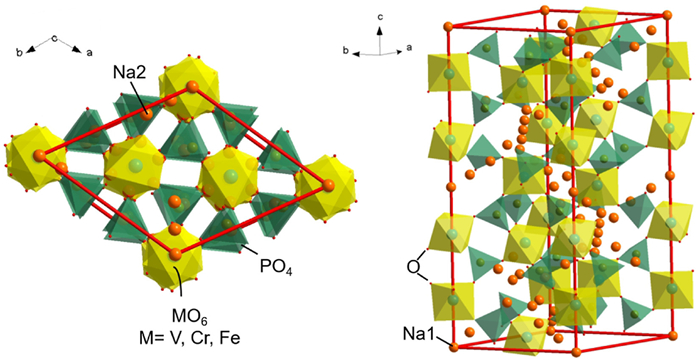
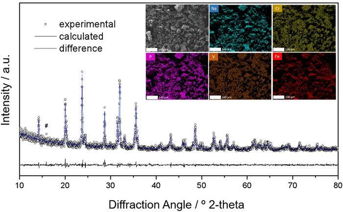
The Na3VCr0.5Fe0.5(PO4)3 is synthesized via a simple sol-gel method, followed by thermal annealing at 750 ℃ under argon atmosphere. The structure exhibits a lantern-like three-dimensional open framework that consists of corner-sharing MO6 octahedra (with M = V/Cr/Fe) and PO4 tetrahedra (Fig. 1). Six lanterns' units build up the primitive cell where two different oxygen environment interstitial sites exist. There are two types of Na sites: Na1 (6b) and Na2 (18e) having 6-fold and 8-fold coordination with oxygen atoms. XRD patterns show that the diffraction peaks can be indexed in a rhombohedral system with an R-3c space group (Fig. 2), and around 16° the peak has been assigned to a superstructure [27,28]. The detailed atomic positions are listed in Table S1 (Supporting information). The lattice parameters (Table 1) are similar to that reported by Li et al. [25], smaller than that of Na3V2(PO4)3 and bigger than those of Na3VCr(PO4)3, as expected due to the crystal radius of V3+ (0.78 Å), Fe3+ (0.785 Å), and Cr3+ (0.755 Å) [21,29].

|
Download:
|
| Fig. 1. Schematic representation of Na3VCr0.5Fe0.5(PO4)3. | |

|
Download:
|
| Fig. 2. XRD pattern and Rietveld refinement of Na3VCr0.5Fe0.5(PO4)3. The inset includes its EDS. | |
|
|
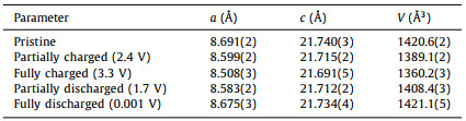
Table 1 Unit cell parameters in the R-3c space group for pristine, charged and discharged Na3VCr0.5Fe0.5(PO4)3, electrodes (Mg-rich phase). |
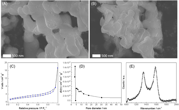
SEM image of the pristine sample shows that the particles surface is not rough, has rounded edges and an average diameter 0.5–1 µm (Fig. 3). The EDS images show that the elements (Na, V, Cr, Fe, P) are distributed uniformly on the particles and confirmed the atomic percentage of the compound (Fig. 2, inset). Moreover, the ICP results confirmed that the Na: V: Cr: Fe atomic ratio for the pristine electrode is 2.986:1.010:0.494:0.495.

|
Download:
|
| Fig. 3. SEM images of Na3VCr0.5Fe0.5(PO4)3: (A) Pristine and (B) after 5 cycles. (C) N2 adsorption/desorption isotherms, (D) pore size distribution and (E) Raman spectrum of Na3VCr0.5Fe0.5(PO4)3. | |
To investigate the textural properties, nitrogen adsorption-desorption measurements were performed (Fig. 3). The specific surface area, pore volume and pore diameter were 3.94 m2/g, 0.024 cm3/g, and 3.82 nm, respectively. In addition, Raman spectrum unveiled vibrational modes of the phosphate groups (~1050 cm−1) belonging to Na3VCr0.5Fe0.5(PO4)3 phase, and revealed that the carbon residua has a highly amorphous character. This carbon phase is characterized by two main bands at ca. 1345 ± 4 cm−1 and ca. 1582 ± 4 cm−1 known as D and G bands and they are assigned to the lack of long range translation symmetry in disordered domains and 'in plane' displacement of carbon atoms in the crystalline domains of graphene sheets with E2g symmetry, respectively [30,31]. The elemental CHNS analysis determined 5.6% of carbon content. Therefore, the addition of propanol during the formation of the gel yields, after further calcination, a carbonaceous residua which is helpful to improve the intrinsic electronic conductivity of Na3VCr0.5Fe0.5(PO4)3 particles.
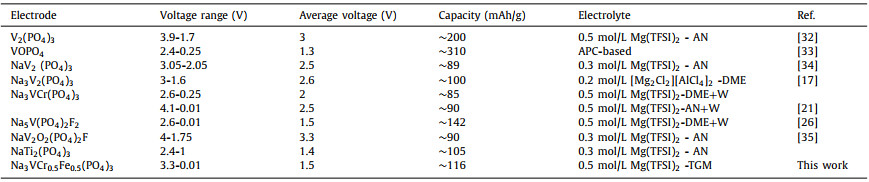
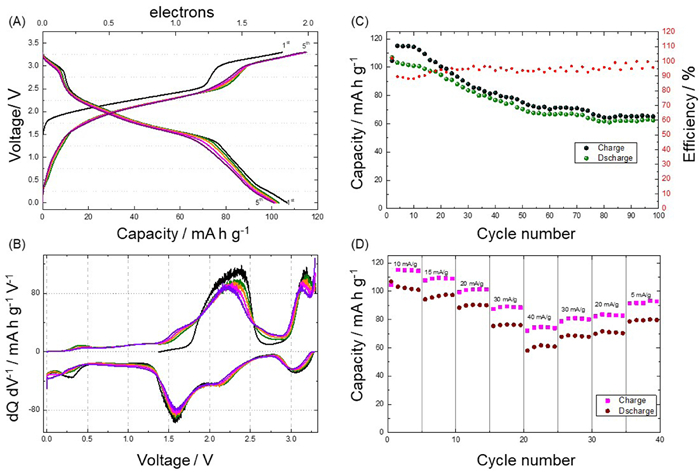
Figs. 4A and B show the galvanostatic and derivative curves obtained for Mg/Na3VCr0.5Fe0.5(PO4)3 cell. Upon charging, it exhibits two pseudo-plateaus at 2.25 and 3.15 V, whose derivative curves revealed a broad peak between 1.75-2.6 V and 3-3.3 V, respectively. It is worthy to note that the theoretical capacity for one electron reaction is 58.4 mAh/g (ca. extraction or insertion of one sodium ion). The first charge the capacity is 105.2 mAh/g (extraction of 1.8 Na+ ion per unit formula). Once that the Na+ ions are extracted, the electrode is washed to avoid the presence of sodium in the electrolyte during the following cycles (see experimental section in Supporting information). However, the rest of the mobile sodium ions (ca. 0.2 Na+ per unit formula) remained in the structure and may affect the cycling properties of the magnesium battery. In any case, the sodium content is low compared to the concentration of the magnesium electrolyte and can be treated as trace contents. On discharge, several reduction peaks are observed at around 3.05, 2.15, 1.6 and 0.23 V. The charge and discharge capacities from first to fifth cycles are around 106-116 and 107-101 mAh/g, respectively. These capacities match with the consumption of one Mg2+ per unit formula (theoretical capacity: 116.8 mAh/g). The cyclic voltammetry curves revealed the reversibility of the reaction in the range between 1.25 V and 2.5 V (Fig. S1 in Supporting information), but the peak at 0.23 V disappears in the the following cycles suggesting the irreversibility of magnesium ions at low potential which is in agreement with the galvanostatic and derivatives curves. A comparison of the different electrochemical properties of NASICON-type structures used in magnesium cells is shown in Table 2. Depending on the magnesium cell configuration (electrolyte, cathode and anode) the electrochemical behaviour showed different performances [17,21,26,32–35].

|
Download:
|
| Fig. 4. (A) Galvanostatic discharge/charge and (B) derivative curves of the Mg/Na3VCr0.5Fe0.5(PO4)3 cell cycled at 10 mA/g. (C, D) Its capacity retention and rate performance. | |
|
|
Table 2 A comparison of the different electrochemical properties of relevant NASICON-type structures used in magnesium cells. |
Regarding the cyclability and capability, the Na3VCr0.5Fe0.5(PO4)3 can be cycled at 30 ℃ with 65% capacity retention after 100 cycles, and afford good rate performance of 104.3, 97.5, 90.7, 77.7 and 60.5 mAh/g at 10, 15, 20, 30 and 40 mA/g, respectively (Figs. 4C and D). For the sake of comparison, the electrochemical performance of Na3VCr(PO4)3 with the same cell configuration has been studied (Fig. S2 in Supporting information). The first charge and discharge capacity is 112.5 and 97.5 mAh/g, respectively. Differently to the Na3VCr0.5Fe0.5(PO4)3 sample, the charge and discharge capacities of Na3VCr(PO4)3 decreased during the first 5 cycles to 73.7 and 70.5 mAh/g. This loss of the capacity at room temperature is ascribed to the loss of the high-voltage capacity due to the migration of V atoms [28,36]. Therefore, the presence of both (iron and chromium) in the vanadium sites provides structural stability when cycling the magnesium cell at 30 ℃ (Fig. 4A).
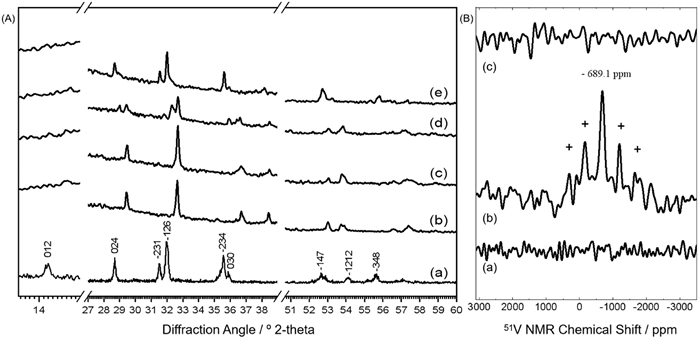
The changes in the structure, 51V local environment and chemical state are studied (Fig. 5). The Bragg peaks of the partially and fully charged electrodes shifted toward higher angles and some peaks disappeared indicating that the structure has changed (Fig. 3). A contraction of cell parameters is observed (Table 1) evidencing efficient extraction of sodium ions from 18e sites [21,28]. As the mobile sodium ions have been extracted from the structure and afterwards removed from the electrolyte, the magnesium ions are inserted during the cell discharge. It showed additional peaks (ca. 29° and 53°) due to the presence of a two-phase system with magnesium rich and poor phase. At the fully discharge state the values of the lattice parameters almost recovered, and hence the reversibility of the process. As Mg2+ (0.72 Å) is about 30% smaller than Na+ (1.02 Å) the former moves easier than sodium implying that the effect of ionic radii is important as recently found in olivine-type materials [16]. Then, a slight cell volume change of 4.2% during a complete cycle is observed. The ex-situ SEM image was recorded after five cycles and revealed that the average particle size is preserved, but the edges have changed. The particles tend to agglomerate with with less rounded edges. Therefore, no apparent volume variation is observed by SEM, in agreement with the ex-situ XRD.

|
Download:
|
| Fig. 5. (A) Ex-situ XRD patterns of Na3VCr0.5Fe0.5(PO4)3: (a) Pristine, (b) partially charged to 2.4 V, (c) fully charged to 3.3 V, (d) partially discharged to 1.4 V and (e) fully discharged to 0.01 V. (B) 51V-NMR of Na3VCr0.5Fe0.5(PO4)3: (a) Pristine, (b) fully charged to 3.3 V and (c) fully discharged to 0.01 V. | |
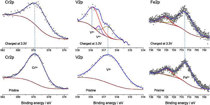
The above phenomena occurred together with oxidation/reduction of the transition metal in Na3V2-x-yAxBy(PO4)3 (with A = Cr(Ⅲ) and B = Fe(Ⅲ)). The XPS spectra at the Cr 2p, Fe 2p and V 2p showed initial oxidation state of Cr3+, Fe3+ and V3+ whose main components of the 2p3/2 core level are at 577.9, 712.5 and 516.5 eV, respectively [37–39]. This confirms the trivalent state of the transition metals in the initial structure (Fig. 6). After the charge at 3.3 V, the Cr 2p and Fe 2p core levels remained unchanged. Contrarily, the V 2p spectrum showed two new asymmetric peaks at 517.4 and 518 eV which could be ascribed to vanadium oxidation to tetravalent and pentavalent states, respectively [21].

|
Download:
|
| Fig. 6. XPS spectra of Na3VCr0.5Fe0.5(PO4)3 at the Cr 2p3/2, V 2p3/2, Fe 2p1/2 and Fe 2p3/2 core levels. | |
The 51V-NMR spectra of pristine, charged and charged/discharged electrodes are registered (Fig. 5B). It is worthy to note that the 51V-NMR signal of pentavalent vanadium compounds without localized d electron are detectable [21,28,40]. In consequence, the 51V signal of Na3VⅢCr0.5Fe0.5(PO4)3 is not observed, but for the fully charged electrode at 3.3 V the signal of V5+ in NaVVCr0.5Fe0.5(PO4)3 is detected at -689.1 ppm with their corresponding spinning sidebands (labeled as "+"). After a full discharge, the NMR signal disappeared entailing the presence of V3+ in NaMgVCr0.5Fe0.5(PO4)3 which should be the main phase present at this stage. It is obviously detected the presence of V5+ in the charged state of the electrode, implying that V5+ should be considered in the redox process. Therefore, while the redox couples such as V3+/V4+/V5+ participate in the electrochemical reaction, the other non-active redox couples such as Cr3+/Cr4+ and Fe2+/Fe3+ could serve as stabilizer to effectively buffer the volume change. These two electrons reaction (ca. by one Mg2+) induced 4.2% volume change which is smaller to the volume variation found in other NASICON-type cathodes such as Na3MnTi(PO4)3 or Na3V1.5Cr0.5(PO4)3 with ca. 8.1% and 7.8%, respectively [41,42].
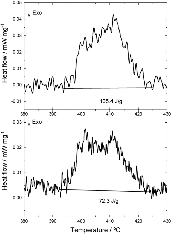
The DSC results of Na3VCr0.5Fe0.5(PO4)3 electrode charged to 3.3 V (104.6 mAh/g) revealed an exothermic process with the main peak appearing at 400–412 ℃ and a thermal effect of 72.3 J/g (Fig. 7). After the second charge to 3.3 V (116 mAh/g) the exothermic peak appeared at similar position, but the thermal effect is a little higher (ca. 105.4 J/g). The introduction of iron and chromium in the structure lead to an increase of the exothermic processes of ca. 32, 90 and 109 ℃ as compared to Na3V2(PO4)3, Na3V2(PO4)2F3 and Na4VMn(PO4)3 electrodes, respectively [43,44]. In view of these results, the choice of doping with iron and chromium could be a good option for batteries where high volumetric/gravimetric energy density and safety are important.

|
Download:
|
| Fig. 7. DSC of Na3VCr0.5Fe0.5(PO4)3 after the (A) first and (B) second charge at 3.3 V. | |
In conclusion, a Mg-coin-cell is fabricated using NASICON-type Na3VCr0.5Fe0.5(PO4)3 cathode exhibiting two-electrons reaction reaching 170 Wh/kg. The V3+/V4+/V5+ redox couple participated in the reaction while the non-active Fe2+/Fe3+ and Cr3+/Cr4+ provided structural stability minimizing strains as confirmed by ex-situ 51V-NMR, XRD and XPS. The cell showed a capacity retention of 65% over 100 cycles and good rate performance at 30 ℃. The dual doping provides different functions to develop advanced electrochemical behaviour.
Declaration of competing interestThere are no conflicts to declare.
AcknowledgmentsThis work was supported by the Scientific Research Funds of Huaqiao University and Xiamen University Foreign Young Talents Program (No. G2022149004L). Sincere thanks to Prof. Z. Wei and Prof. Y. Yang from the College of Materials Science and Engineering (Huaqiao University) and College of Chemistry and Chemical Engineering (Xiamen University) for supporting the research activities. The author thanks Peixuan Lu for the kind discussions.
Supplementary materialsSupplementary material associated with this article can be found, in the online version, at doi:10.1016/j.cclet.2023.109391.
| [1] |
D. Aurbach, Z. Lu, A. Schechter, et al., Nature 407 (2000) 724. DOI:10.1038/35037553 |
| [2] |
M. Zhang, S. Feng, Y. Wu, Y. Li, Acta Phys. Chim. Sin. 39 (2023) 2205050. |
| [3] |
D. Imamura, M. Miyayama, M. Hibino, T. Kudo, J. Electrochem. Soc. 150 (2003) A753. DOI:10.1149/1.1571531 |
| [4] |
R. Zhang, X. Yu, K.W. Nam, et al., Electrochem. Commun. 23 (2012) 110. DOI:10.1016/j.elecom.2012.07.021 |
| [5] |
C. Yuan, Y. Zhang, Y. Pan, et al., Electrochim. Acta 116 (2014) 404. DOI:10.1016/j.electacta.2013.11.090 |
| [6] |
L. Wang, Z.H. Wang, P.E. Vullum, et al., Nano Lett. 18 (2018) 763. DOI:10.1021/acs.nanolett.7b03978 |
| [7] |
Y.L. Liang, H.D. Yoo, Y.F. Li, et al., Nano Lett. 15 (2015) 2194. DOI:10.1021/acs.nanolett.5b00388 |
| [8] |
B. Liu, T. Luo, G. Mu, et al., ACS Nano 7 (2013) 8051. DOI:10.1021/nn4032454 |
| [9] |
H.D. Yoo, Y.L. Liang, H. Dong, et al., Nat. Commun. 8 (2017) 339. DOI:10.1038/s41467-017-00431-9 |
| [10] |
X.Q. Sun, P. Bonnick, L.F. Nazar, ACS Energy Lett. 1 (2016) 297. DOI:10.1021/acsenergylett.6b00145 |
| [11] |
R. Yokozaki, H. Kobayashi, I. Honma, Ceram. Int. 47 (2021) 10236-10241. DOI:10.1016/j.ceramint.2020.10.184 |
| [12] |
N. Kitamura, T. Imura, N. Ishida, C. Ishibashi, Y. Idemoto, ACS Omega 7 (2022) 46915-46921. DOI:10.1021/acsomega.2c06633 |
| [13] |
R. Ruiz, C. Pérez-Vicente, S. Rubio, et al., Energy Storage Mater. 48 (2022) 12-19. DOI:10.1016/j.ensm.2022.02.047 |
| [14] |
Y. Wang, Z. Liu, C. Wang, et al., Adv. Mater. 30 (2018) 1802563. DOI:10.1002/adma.201802563 |
| [15] |
S. Rubio, Z. Liang, Y. Li, et al., Electrochim. Acta 404 (2022) 139738. DOI:10.1016/j.electacta.2021.139738 |
| [16] |
C. Pérez-Vicente, S. Rubio, R. Ruiz, et al., Small 19 (2023) 2206010. DOI:10.1002/smll.202206010 |
| [17] |
Y. Li, Q. An, Y. Cheng, et al., Nano Energy 34 (2017) 188. DOI:10.1016/j.nanoen.2017.02.012 |
| [18] |
M. Cabello, R. Alcántara, F. Nacimiento, et al., Electrochim. Acta 246 (2017) 908-913. DOI:10.1016/j.electacta.2017.06.080 |
| [19] |
Y. Fei, Y. Man, J. Sun, et al., Small 19 (2023) 2301954. DOI:10.1002/smll.202301954 |
| [20] |
Y. Man, P. Jaumaux, Y. Xu, et al., Sci. Bull. 68 (2023) 1819-1842. DOI:10.1016/j.scib.2023.07.027 |
| [21] |
S. Rubio, R. Liu, X. Liu, et al., J. Mater. Chem. A 7 (2019) 18081-18091. DOI:10.1039/C9TA05608D |
| [22] |
Z. Jian, W. Han, X. Lu, et al., Adv. Energy Mater. 3 (2013) 156-160. DOI:10.1002/aenm.201200558 |
| [23] |
R. Liu, H. Liu, T. Sheng, et al., ACS Appl. Energy Mater. 1 (2018) 3603-3606. DOI:10.1021/acsaem.8b00889 |
| [24] |
X. Liu, G. Feng, E. Wang, et al., ACS Appl. Mater. Interfaces 11 (2019) 12421-12430. DOI:10.1021/acsami.8b21257 |
| [25] |
H. Li, Y. Wang, X. Zhao, et al., ACS Energy Lett. 8 (2023) 3666-3675. DOI:10.1021/acsenergylett.3c01183 |
| [26] |
S. Rubio, Z. Liang, X. Liu, et al., Energy Storage Mater. 38 (2021) 462-472. DOI:10.1016/j.ensm.2021.03.035 |
| [27] |
F. Lalere, J.B. Leriche, M. Courty, et al., J. Power Sources 247 (2014) 975-980. DOI:10.1016/j.jpowsour.2013.09.051 |
| [28] |
R. Liu, G. Xu, Q. Li, et al., ACS Appl. Mater. Interfaces 9 (2017) 43632. DOI:10.1021/acsami.7b13018 |
| [29] |
R.D. Shannon, Acta Crystal. A 32 (1976) 751-767. DOI:10.1107/S0567739476001551 |
| [30] |
A. Sadezky, H. Muckenhuber, H. Grothe, R. Niessner, U. Pöschl, Carbon 43 (2005) 1731-1742. DOI:10.1016/j.carbon.2005.02.018 |
| [31] |
A. Criado, P. Lavela, C. Pérez-Vicente, G.F. Ortiz, J.L. Tirado, J. Electroanal. Chem. 856 (2020) 113694. DOI:10.1016/j.jelechem.2019.113694 |
| [32] |
Z.D. Huang, T. Masese, Y. Orikasa, T. Mori, K. Yamamoto, RSC Adv. 5 (2015) 8598. DOI:10.1039/C4RA14416C |
| [33] |
L.M. Zhou, Q. Liu, Z.H. Zhang, et al., Adv. Mater. 30 (2018) 1801984. DOI:10.1002/adma.201801984 |
| [34] |
J. Zeng, Y. Yang, S.B. Lai, et al., Chem. Eur. J. 23 (2017) 16898-16905. DOI:10.1002/chem.201704303 |
| [35] |
J.J. Wang, S.S. Tan, G.B. Zhang, et al., Sci. China Mater. 63 (2020) 1651-1662. DOI:10.1007/s40843-020-1311-1 |
| [36] |
R. Liu, S. Zheng, Y. Yuan, et al., Adv. Energy Mater. 11 (2021) 2003256. DOI:10.1002/aenm.202003256 |
| [37] |
D. Park, Y.S. Yun, J.M. Park, J. Colloid Interface Sci. 317 (2008) 54. DOI:10.1016/j.jcis.2007.09.049 |
| [38] |
D. Dwibedi, R. Gond, P. Barpanda, Chem. Mater. 31 (2019) 7501-7509. DOI:10.1021/acs.chemmater.9b02220 |
| [39] |
M.J. Aragón, P. Lavela, G.F. Ortiz, J.L. Tirado, J. Electrochem. Soc. 162 (2015) A3077. DOI:10.1149/2.0151502jes |
| [40] |
T. Broux, T. Bamine, L. Simonelli, et al., J. Phys. Chem. C 121 (2017) 4103-4111. |
| [41] |
H. Li, M. Xu, C. Gao, et al., Energy Storage Mater. 6 (2020) 325-333. |
| [42] |
W. Zhang, Y. Wu, Z. Xu, et al., Adv. Energy Mater. 12 (2022) 2201065. DOI:10.1002/aenm.202201065 |
| [43] |
R.R. Samigullin, O.A. Drozhzhin, E.V. Antipov, ACS Appl. Energy Mater. 5 (2022) 14-19. DOI:10.1021/acsaem.1c03151 |
| [44] |
R.R. Samigullin, M.V. Zakharkin, O.A. Drozhzhin, E.V. Antipov, Energies 16 (2023) 3051. DOI:10.3390/en16073051 |