 2024, Vol. 35


b School of Chemical Engineering, Nanjing University of Science & Technology, Nanjing 210094, China;
c Nantong Junjiang Material Science and Technology Co., Ltd., Haimen 226136, China
Integrating TiO2 nanomaterials into film structures presents an efficient pathway to sustain stable photocatalysis or enhance performance through collaborative interactions with the support substrates [1–3]. The TiO2-based photocatalytic thin films are fabricated mainly into three forms: (1) TiO2 porous films through the sol-gel process using templates or TiO2 nanotube arrays via electrochemical deposition [4–6]. These films always need solid substrates to form or deposit TiO2 structures. As the film bulk is composed of TiO2, the films are robust without flexibility. (2) TiO2 nanoparticles (TiNP) combined with or grown on a flexible substrate [7]. The loading of TiO2 nanoparticles largely relies on the surface area of the substrates and the binding interactions between them. It thus still has the risk of TiO2 leakage during usage, which may bring severe effects to both human health and the environment [8]. (3) Aggregated TiO2 nanoparticles covered by other layers to form hybrid films [9,10]. Although the covered layers on TiO2 are generally transparent and unlikely to impact light exposure, they may impede the direct contact between reactant molecules and active TiO2 during catalysis processes. Therefore, developing TiO2 photocatalytic thin film with convenient flexibility, high activity, and well stability remains challenging for exploring their usage in various catalysis occasions.
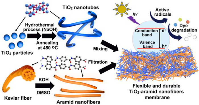
Inspired by the reports on flexible composite films [11–16], this work aims to fabricate a soft and durable TiO2-based photocatalytic membrane capable of efficiently degrading dyes. By using 1D TiO2 nanotubes (TiNT) and aramid nanofibers (ANF) as flexible substrates, we interweaved them into homogeneous TiNT-ANF membranes (TANFs) via a facile vacuum filtration process (Fig. 1). Due to similar 1D dimensions and hydrogen bondings interactions, the well-intercalated TiNT and ANF enabled the hybrid membranes show high mechanical strength and morphological stability, which can stand bending, sonication, and a long-time immersion in solution. The light adsorption range of TiO2 in TANFs also expanded to visible light with the active sites accessible to external molecules. The membrane thus exhibited excellent photocatalytic performance for the decomposition of various dyes and could maintain activity without a loss for repeated usage. Moreover, the membrane demonstrated strong antimicrobial properties, which also could support its prolonged usage for dye degradation in water. In contrast to other TiO2-based hybrid films for dye degradation, the TANF has the advantages as follows: (1) It avoids the leakage or aggregation risk of TiO2 nanomaterials; (2) It may achieve high TiO2 content with accessibility; (3) It possesses the flexibility to adapt to different reaction containers and conditions; (4) It could be easy recovered for repeated usage; (5) It could be easily prepared by relatively simple procedures.

|
Download:
|
| Fig. 1. The scheme for the fabrication of TiO2 nanotubes-aramid nanofibers hybrid films (TANFs) as photocatalysts for dye degradation. | |
Compared with nanoparticles, nanotubes may greatly reduce the risk of leakage or aggregation and facilitate the maintenance of accessible active sites during usage. Moreover, TiNT also could strengthen photocatalytic properties by enhancing electron transfer and light harvesting [17,18]. TiNPs with an average size of 30 nm converted into TiNTs with the same anatase crystalline phase after the hydrothermal process and annealing at 450 ℃ (Figs. S1 and S2 in Supporting information). Most synthesized TiNTs have open ends, possessing a diameter of about 15 nm, a wall thickness of 3–4 nm, and a length in micrometer dimension.
Although TiNTs possess a high aspect ratio, they are still difficult to form thin films solely due to their brittle nature. ANF whose composition is poly(paraphenylene terephthalamide) (PPTA), are fascinating nanomaterials with good electrical conductivity, flexibility, mechanical robustness, and chemical/physical stability [19]. They have been widely used as membrane matrices for various applications of separation, strain sensors, electronic devices, etc. [20–22]. However, ANF was rarely utilized as a support for photocatalysts. To the best of our knowledge, there is no report of soft TiNT-ANF composite film for the photocatalysis application of dye degradation.
Single ANF with a dimension of 3–30 nm in diameter and ~10 µm in length could be isolated from Kevlar fibers by KOH hydrolysis (Fig. S1). The TANFs with different mixing ratios were fabricated by a facile solution-based interweaving process and vacuum filtration (Table S1 in Supporting information). Due to similar fiber morphology, TiNTs and ANFs were inclined to intertwine together during the mixing process and form homogeneous mixture films after vacuum filtration on a porous substrate. In contrast to the pure ANF film, TANFs have more plane surfaces with fewer wrinkles (Fig. S3 in Supporting information). The colors of TANFs turned to light yellow-white. The thicknesses of TANFs increased with the additional amount of TiNTs. It is worth noting that the films with higher mixing ratios of TiNTs and ANFs (> 10:1) may become brittle and prone to breakage.
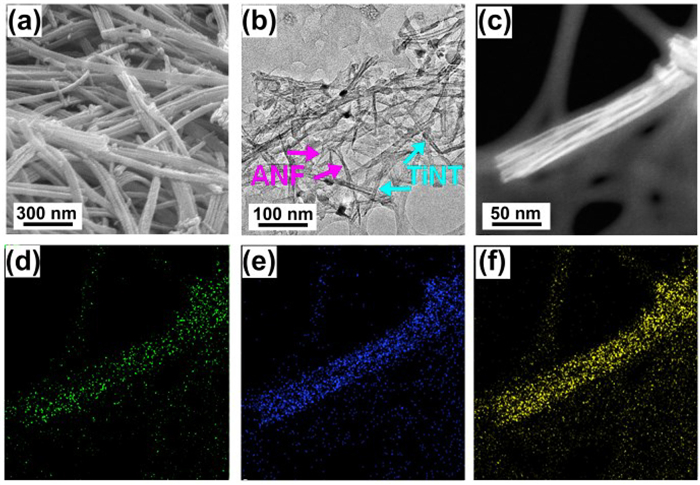
SEM observation of TANFs indicated the interwoven state of the nanotubes and nanofibers (Fig. 2a and Fig. S4 in Supporting information). There were plenty of pores in the films. From the TEM image, we can further observe the intercalated state of TiNTs with the bundles of ANFs. The ANFs displayed relatively low contrast in the TEM image, while TiNTs were darker (Fig. 2b). The elemental mappings of the TANFs illustrated the homogenous distribution of N, O, and Ti elements in the films (Figs. 2c-f) and the well-mixing state of ANFs and TiNTs.

|
Download:
|
| Fig. 2. (a) The SEM image, (b) TEM image and (c) high-angel annular dark-field (HAADF)-STEM image of T2ANF. The corresponding elemental mappings of displaying element distribution of (d) N, (e) O and (f) Ti. | |
The XRD patterns of TANFs exhibited the diffraction peaks at 25°, 39°, 48°, 54°, 55°, 63°, 70°, and 75° (Fig. S5 in Supporting information), which could be assigned as (101), (004), (200), (105), (211), (204), (220) and (215) phases from anatase TiO2 crystalline [23]. The ANFs could display a broad diffraction peak at 21° due to the axial orientation of PPTA molecules (Fig. S6 in Supporting information) [24]. However, the intense crystalline nature of TiO2 may mask the diffraction patterns from ANFs. Compared with TiNTs, the (101) diffraction peak of TANFs around 25° shifts to a higher degree. It implied the decrease of the lattice spacing after interwoven with ANFs, which might be due to the TiO2-PPTA interaction in TANFs.
The full-scan spectrum of T2ANF in the range of 0–1200 eV revealed the presence of C, O, N, and Ti elements (Fig. S7a in Supporting information). The high-resolution Ti 2p spectrum showed Ti 2p1/2 and Ti 2p3/2 splitting peaks at 458.2 and 463.9 eV (Fig. S7b). Compared to pure TiO2, the peaks were observed to shift towards the higher energy regions (Fig. S8 in Supporting information). This shift should result from the interactions between ANF and TiNT, which affect the electron density of TiO2 [25]. The O 1s XPS spectrum of T2ANF can deconvolute into three peaks (Fig. S7c in Supporting information). The peaks at 529.7 eV and 532.3 eV correspond to the lattice oxygen (Ti–O) in TiO2 and O=C-C in ANF [26]. The peak at 531.5 eV should be attributed to Ti-OHx from the hydrogen bonding with the amine group of PPTA (Fig. S9 in Supporting information), which was also shifted and strengthened compared to the O 1s XPS spectrum of TiO2 (Fig. S8). The C 1s XPS spectrum of T2ANF revealed the C–C/C = C coordination (284.6 eV), the C–N (285.4 eV), and C = O (287.9 eV) species in ANFs (Fig. S7d in Supporting information) [27].
The adsorption of pure TiNTs is primarily limited to the UV range of 200–350 nm (Fig. S10a in Supporting information). The calculated band gap was about 3.44 eV, indicating the wide band gap of anatase TiO2 [28]. ANFs exhibited three absorption peaks around 228, 287, and 400 nm, respectively. These peaks are associated with the π–π conjugations and the partial protonation of PPTA [29,30]. TANFs exhibited broader light adsorption, extending to the visible light range beyond 400 nm (Fig. S10b in Supporting information). According to the analysis, the band gap of T2ANF was 2.58 eV It has been suggested that an efficient photocatalyst should have a band gap of less than 3 eV, as it could lead to more efficient utilization of light energy [31].
Based on photoluminescence (PL) spectroscopy, we compared the charge-transfer efficiency in TANF and TiNT (Fig. S11 in Supporting information). The PL emission peak located at 515 nm is indicative of the band-to-band recombination process of electrons-holes [32]. The lower emission intensity means fewer electrons recombined within holes and higher separation efficiency of electrons and holes. Compared to TiNT, TANF exhibited a significant decrease in PL intensity. This implied that the integration of TiNT with ANF can inhibit the recombination of photo-generated electrons and holes.
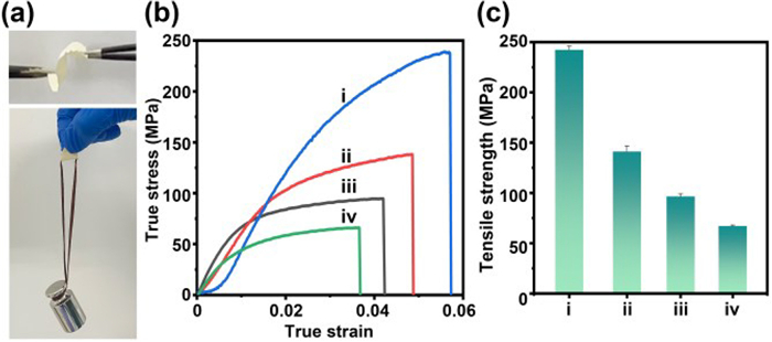
The interwoven ANFs with TiNT resulted in a substantial improvement in the mechanical strength of TANFs. TANFs have softness and could bend (> 90°) at least 1000 times without cracks. Suspending < 300 g weight in the middle of the films will not cause fractures or breaks (Fig. 3a). The true stress-strain curves and tensile strength results (Figs. 3b and c) showed the mechanical properties of TANFs with different TiNT: ANF ratios. The pure ANF film exhibited a tensile strength of 237 MPa and a low strain value of 0.06. With the increase in TiO2 amounts, the tensile strength showed a nearly linear decrease from 41.3% to 71.6%. However, the mechanical strength of the TANFs was still higher than the reported TiO2-based membranes or TiO2-filled polymer composite films [11,33].

|
Download:
|
| Fig. 3. The images of (a) bending TANF and weight suspension in the center of TANF. (b) The true stress-strain curve of (ⅰ) ANF, (ⅱ) T1ANF, (ⅲ) T2ANF, (ⅳ) T3ANF. (c) The tensile strength of TANFs.. | |
According to the photocatalysis mechanism, electrons and holes produced by light excitation of TiO2 could convert into •O2− and hydroxyl (•OH) radicals by reacting with oxygen and water. •O2− and •OH radicals could promote the degradation of the dyes [34]. To investigate the active radicals generated from TANFs during the photocatalysis process, EPR spin trapping technique was applied with DMPO as a spin trap (Fig. S12 in Supporting information). There was no EPR signal detected when the process was in the dark. After 20 min of illumination, TANF displayed a characteristic quadruplet with a signal-to-intensity ratio of 1:2:2:1. It demonstrated the generation of •OH radical from the films. The higher EPR signal intensity of TANF than TiNTs indicated that TANF could generate more •OH radicals during photocatalysis.
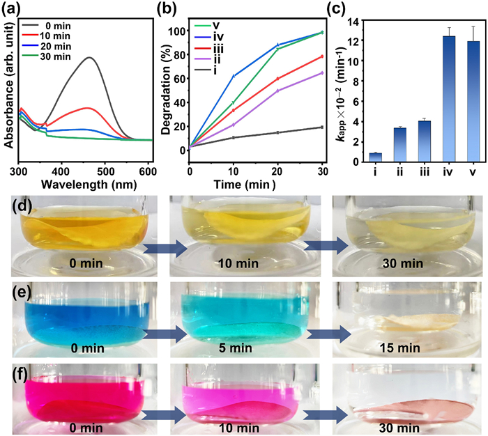
The photocatalytic efficiency of the TANFs was investigated and compared in terms of their ability to degrade dyes. With softness and strength, TANFs can conveniently incorporate into the dye solution as a photocatalyst. Fig. 4a and Fig. S13a (Supporting information) showed the UV–vis spectra of methyl orange (MO) solution (10 mL, 20 ppm) under UV irradiation (365 nm, 300 W) with and without T2ANF. The dye degradation was evaluated based on the intensity changes of the adsorption peak at 465 nm. In the absence of TiO2, dye molecules had low degradation efficiency under UV irradiation (Fig. S13 in Supporting information). The addition of wet TANFs in the dye solution led to a small decrease (3%) in the peak intensity (Fig. S14 in Supporting information). It implied the adsorption of dye molecules on the surface of the membrane, which may increase the local concentration and improve the catalysis efficiency. As the molecular adsorption on TiNT or ANF is mainly by van der Waals interactions, the products from dye degradation should desorb easily from the membrane and not affect the recovery of the photocatalyst. Promoted by the TANF, the intensity of MO at 465 nm rapidly decreased and almost completely faded within 30 min under UV irradiation (Figs. 4a and d). The degradation efficiency of various TANFs was 70% (T1ANF), 99% (T2ANF), and 99% (T3ANF) under 30 min of irradiation time (Fig. 4b). The order of the kinetic parameter (Kapp) values was T2ANF > T3ANF > T1ANF > TiNT > > ANF (Fig. 4c and Fig. S15 in Supporting information). Although increasing the amount of TiNTs in the film should increase the active sites, a high additional amount may also reduce the porous volume, which is not conducive to dye molecule penetration. T2ANF, which have lower density (0.45 g/cm3) exhibited higher catalytic efficiency compared to T1ANF (0.94 g/cm3) and T3ANF (1.2 g/cm3).

|
Download:
|
| Fig. 4. (a) The UV–vis spectra for the degradation of methyl orange with T2ANF under light irradiation. (b) The degradation curves of MO and (c) the Kapp values by using (ⅰ) ANF, (ⅱ) TiNT, (ⅲ) T1ANF, (ⅳ) T2ANF, and (ⅴ) T3ANF as photocatalysts. The color changes of (d) MO solution, (e) MB solution and (f) RhB solution during the photocatalysis process by T2ANF. | |
To further understand the catalytic mechanism of TANF, quenching experiments were conducted with tert–butyl alcohol as the •OH quencher and benzoquinone as the •O2− quencher, respectively (Fig. S16 in Supporting information). The addition of 5 mmol/L tert–butyl alcohol in the reaction system was shown to inhibit the dye degradation by about 40%, while the degradation percentage decreased about 70% in the presence of 5 mmol/L benzoquinone. These results confirmed that •O2− and •OH radicals produced from TiO2 were primary radical species for promoting dye degradation.
Besides MO, the effective degradation of other dyes, such as methylene blue (MB) and Rhodamine B (RhB), can also be achieved with comparable photocatalytic efficiency (Figs. 4e and f, and Fig. S17 in Supporting information). As TANF is highly durable, it can be reused multiple times by washing and drying (Fig. S18a in Supporting information). After being used five times, its efficiency can remain at almost no loss. The excellent stability of the catalytic activity can be attributed to the intricate integration of TiNTs and ANFs. It not only enhances the optical property but also avoids the leakage of TiO2 and facilitates the access of external molecules with active TiO2. After long-time immersion in water (> 3 days) or subjected to ultra-sonication, the adsorption peak from TiO2 was still not detected in the dispersion with TANF (Fig. S18b in Supporting information). By contrast, TiNPs in the ANF hybrid membrane fabricated by a similar process of TANF were prone to leakage, leading to a turbid and white supernatant (Fig. S19 in Supporting information).
ANFs are prone to degradation under UV light and weaken their mechanical strength. Nevertheless, the TiO2 addition can significantly enhance the UV-resistance capability of ANFs [35]. The FTIR spectra of the pure ANF membrane before and after UV irradiation, revealed significant changes within the range of 1000–2000 cm−1 (Fig. S20a in Supporting information). In contrast, T2ANF exhibited negligible changes in vibration peaks upon UV irradiation (Fig. S20b in Supporting information). The mechanical measurement on the T2ANF after repeated photocatalysis (5 times) also showed well maintenance (> 90%) of the tensile strength (Fig. S21 in Supporting information). This result further proved that TANFs possess durability for photocatalysis applications.
In order to ensure prolonged usage in water, the photocatalyst’s antimicrobial property is also important for effectively degrading dyes. We detected the antimicrobial effect of TANFs by checking the bacteria (E. coli) growth after cultivation with TANF. It was evident that the presence of T2ANF led to a significant decrease in the colonies of E. coli compared to the control group without T2ANF (Fig. S22 in Supporting information). The free hydroxyl radicals (•OH) produced from TiO2 may induce the biocidal action of TANF membrane [36].
In conclusion, we successfully fabricated a soft and durable photocatalyst membrane (TANF) by facile preparation strategy from TiNT and ANF. They could intricately interweave together in TANFs, which not only avoids the risk of TiO2 leakage but also bring good mechanical strength to the TiO2-based film. The interactions with aramid nanofiber effectively expand the optical adsorption range of TiO2 and suppress the electron-hole recombination during the photocatalytic process, leading to enhanced efficiency in dye degradation. With flexibility and durability, TANF can be easily recovered after usage and maintain its activity without a loss for repeated photocatalysis usage. Its antibacterial effect may also support long-time immersion in water. The work presents a new TiO2-based photocatalytic hybrid membrane with a flexible matrix, well durability without leakage of active TiO2, and an easily accessible network structure, which may facilitate their usage in different conditions over an extended time. The convenient fabrication process also permits the integration of additional functional additives to achieve more active photocatalytic thin films for other photocatalytic processes.
Declaration of competing interestThe authors declare that they have no known competing financial interests or personal relationships that could have appeared to influence the work reported in this paper.
AcknowledgmentsThank for the financial supports from the Instrument & Equipment Open Funding of Nanjing University of Science and Technology, National Natural Science Foundation of China (Nos. 21875108 and 22105103), the Natural Science Foundation of Jiangsu Province (No. BK20200471), the Fundamental Research Funds for the Central Universities (No. 30921013106), the technical cooperation project with Nantong Junjiang Material Science and Technology Co., Ltd. (No. 2022320104001955) and the Key R&D Project of Shanxi Province (No. 2022JBGS3–12).
Supplementary materialsSupplementary material associated with this article can be found, in the online version, at doi:10.1016/j.cclet.2023.109193.
| [1] |
N. Nalajala, K.K. Patra, P.A. Bharad, et al., RSC Adv. 9 (2019) 6094-6100. DOI:10.1039/C8RA09982K |
| [2] |
R.S. Pedanekar, S.K. Shaikh, K.Y. Rajpure, Curr. Appl. Phys. 20 (2020) 931-952. DOI:10.1016/j.cap.2020.04.006 |
| [3] |
X. Gao, M. Li, F. Zhou, et al., J. Colloid Interface Sci. 600 (2021) 127-137. DOI:10.1016/j.jcis.2021.05.005 |
| [4] |
B. Pant, M. Park, S.J. Park, Coatings 9 (2019) 613. DOI:10.3390/coatings9100613 |
| [5] |
R. Zazpe, R. Krumpolec, H. Sopha, et al., ACS Appl. Nano Mater. 3 (2020) 12034-12045. DOI:10.1021/acsanm.0c02553 |
| [6] |
Y. Ye, Y. Feng, H. Bruning, et al., Appl. Catal. B: Environ. 220 (2018) 171-181. DOI:10.1016/j.apcatb.2017.08.040 |
| [7] |
H. Shi, X. Wang, M. Zheng, et al., Adv. Mater. Interfaces 3 (2016) 1600588. DOI:10.1002/admi.201600588 |
| [8] |
O. Kose, M. Tomatis, L. Leclerc, et al., Chem. Res. Toxicol. 33 (2020) 2324-2337. DOI:10.1021/acs.chemrestox.0c00106 |
| [9] |
I. Martínez, R. Santillán, I.F. Camargo, et al., Polymers(Basel) 14 (2022) 4666. |
| [10] |
E. Bletsa, P. Merkl, T. Thersleff, et al., Chem. Eng. J. 454 (2023) 139971. DOI:10.1016/j.cej.2022.139971 |
| [11] |
H. Zhao, R. Su, L. Teng, et al., Nanoscale 14 (2022) 1653-1669. DOI:10.1039/D1NR06244A |
| [12] |
X. Li, K. Cai, M. Gao, et al., Nano Energy 89 (2021) 106309. DOI:10.1016/j.nanoen.2021.106309 |
| [13] |
S. Zhu, J. Forth, G. Xie, et al., ACS Nano 14 (2020) 11215-11224. DOI:10.1021/acsnano.0c02923 |
| [14] |
J. Fu, Q. Wang, J.B. Schlenoff, ACS Appl. Mater. Interfaces 7 (2015) 895-901. DOI:10.1021/am5074694 |
| [15] |
Y. Li, Y. Yu, L. Wu, et al., Appl. Surf. Sci. 273 (2013) 135-143. DOI:10.1016/j.apsusc.2013.01.213 |
| [16] |
M.I. Baig, J.D. Willott, W.M. de Vos, J. Membrane Sci. 615 (2020) 118502. DOI:10.1016/j.memsci.2020.118502 |
| [17] |
S. Ozkan, N.T. Nguyen, A. Mazare, et al., ChemElectroChem 5 (2018) 3183-3190. DOI:10.1002/celc.201801136 |
| [18] |
H.Y. Yang, W.Y. Rho, S.K. Lee, et al., Nanomaterials 9 (2019) 326. DOI:10.3390/nano9030326 |
| [19] |
Y. Zhao, X. Li, J. Shen, et al., J. Mater. Chem. A 8 (2020) 7548-7568. DOI:10.1039/D0TA01654C |
| [20] |
J. Wang, Y. Lin, A. Mohamed, et al., J. Mater. Chem. C 9 (2021) 575-583. DOI:10.1039/D0TC02983A |
| [21] |
Z. Zhang, S. Yang, P. Zhang, et al., Nat. Commun. 10 (2019) 2920. DOI:10.1038/s41467-019-10885-8 |
| [22] |
S. Zhu, Z. Lei, Y. Dou, et al., Chem. Eng. J. 452 (2023) 139403. DOI:10.1016/j.cej.2022.139403 |
| [23] |
D. Reyes-Coronado, G. Rodríguez-Gattorno, M.E. Espinosa-Pesqueira, et al., Nanotechnology 19 (2008) 145605. DOI:10.1088/0957-4484/19/14/145605 |
| [24] |
H. Kong, C. Teng, X. Liu, et al., RSC Adv. 4 (2014) 20599-20604. DOI:10.1039/C4RA00801D |
| [25] |
X. Niu, W. Yan, C. Shao, et al., Appl. Surf. Sci. 466 (2019) 882-892. DOI:10.1016/j.apsusc.2018.10.019 |
| [26] |
X. Wu, S. Yin, Q. Dong, et al., Appl. Catal. B: Environ. 142- 143 (2013) 450-457. |
| [27] |
Y.L. Pang, A.Z. Abdullah, Chem. Eng. J. 214 (2013) 129-138. DOI:10.1016/j.cej.2012.10.036 |
| [28] |
Ł. Haryński, K. Grochowska, J. Karczewski, et al., ACS Appl. Mater. Interfaces 12 (2020) 3225-3235. DOI:10.1021/acsami.9b19206 |
| [29] |
M. Yang, Q.K. Cao, B. Yeom, et al., J. Compos. Mater. 49 (2015) 1873-1879. DOI:10.1177/0021998315579230 |
| [30] |
J. Luo, M. Zhang, B. Yang, et al., Appl. Nanosci. 9 (2019) 631-645. DOI:10.1007/s13204-018-0722-z |
| [31] |
H. Yan, X. Wang, M. Yaon, et al., Prog. Nat. Sci. 23 (2013) 402-407. DOI:10.1016/j.pnsc.2013.06.002 |
| [32] |
G.P. Agrawal, N.K. Dutta, Recombination mechanisms in semiconductors, in: G.P. Agrawal, N.K. Dutta (Eds.), Semiconductor Lasers, Springer, New York, 1993, pp. 74–146.
|
| [33] |
A. Holm, M. Hamandi, F. Simonet, et al., Appl. Catal. B: Environ. 253 (2019) 96-104. DOI:10.1016/j.apcatb.2019.04.042 |
| [34] |
N. Bao, Y. Li, Z. Wei, et al., J. Phys. Chem. C 115 (2011) 5708-5719. DOI:10.1021/jp1100939 |
| [35] |
X. Liu, W. Yu, N. Pan, J. Appl. Poly. Sci. 120 (2011) 552-556. DOI:10.1002/app.33200 |
| [36] |
A. Kubacka, M.S. Diez, D. Rojo, et al., Sci. Rep. 4 (2014) 4134. DOI:10.1038/srep04134 |