 2024, Vol. 35


b School of Life Science, Jinggangshan University, Ji’an 343009, China;
c CAS Key Laboratory of Green Process and Engineering, National Engineering Research Center of Green Recycling for Strategic Metal Resources, Institute of Process Engineering, Chinese Academy of Sciences, Beijing 100190, China;
d Biomass Molecular Engineering Center and Anhui Provincial Key Laboratory of Microbial Pest Control, Anhui Agricultural University, Hefei 230036, China;
e Jiangxi Ganfeng Recycling Technology Co. LTD., Xinyu 338004, China
In recent years, the demand for ternary lithium-ion batteries (LIBs) has risen dramatically [1–3], so it is necessary to effectively recycle the cathode materials of discarded ternary lithium batteries in order to minimize the resource depletion and at the same time reduce the environmental pollution [4]. Battery active cathode materials are mainly lithium transition metal oxides, such as LiNi1−x−yCoxMnyO2 (NCM) [5]. Therefore, during the recycling process of retired Li-ion ternary batteries, a large amount of solid waste residue containing precious metals such as Ni, Co, and Mn is generated. The metal contents are usually 5%−30% Co, 0–10% Ni, 5%−12% Mn and 7%−17% Cu, etc. [6,7]. All these metals have recycling value [8,9], and the recovery of valuable metal elements from solid waste residues can maximize the use of resources [10,11]. Compared with the traditional stepwise metal ion recovery process, the directly recovery of Cu, Ni, Co, and Mn ions as cathode copper and ternary precursors for the preparation of ternary lithium batteries have more extensive market prospect [12].
In general, copper slag derived from traditional hydrometallurgy has been separated and recovered by chemical precipitation, ion exchange, adsorption, solvent extraction, etc. [13,14]. Leila Miganei et al. [15] recovered 80%−90% copper from copper slag through separation, roasting, hydrochloric acid leaching, carbonate precipitation, precipitation complexation, and metal solvent extraction. Obviously, this kind of recycling process is cumbersome, the purity of the product is difficult to improve, and high drug consumption. Prem et al. [16] also reported the recovery potential of copper slag, due to its low content of precious metals, the experiments were conducted to recover cement additives and metal salt solutions directly, and the product is not economically efficient. Guorui Qu et al. [17] recovered Co, Cu, Ni, and Fe from copper slag in the form of alloys, which provided an opportunity for the recovery of copper from the smelted products to prepare high value-added products. Copper slag recycling has realized the transformation from shortening the process to improving the product value and economic benefits [18]. However, the problems of low product purity, low metal recovery rate, and high pharmaceutical consumption are still a great challenge for the efficient utilization of solid waste resources [19–22].
Herein, we proposed a novelty recycling mode to achieve the recovery of highly pure cathode copper and widely used ternary precursors from complex CuS slag. The environment-friendly technology of acid leaching-selective electrodeposition of copper-deep impurity removal-regeneration of the ternary precursors was adopted to recover and treat CuS slag. The experimental results showed that copper cathode and NCM523 have been synthesized successfully. In addition, the technological conditions of acid leaching, electrodeposition of copper, and impurity removal were optimized and evaluated comprehensively. This technology provides an effective method for recycling of waste ternary lithium battery residue.
CuS slag samples were obtained from Jiangxi Ganfeng Lithium Co., LTD. (the specific source of production of CuS slag is given in Fig. S1 in Supporting information). The cathode of electrodeposited copper comes from copper foil stripped from waste lithium batteries (waste lithium batteries from Jiangxi Ganfeng Lithium Co., LTD.). The CuS slag is manually ground and dried in the oven through a 100-mesh sieve to obtain uniform CuS slag powder. The metal element composition of CuS slag was analyzed by means of vitriolic acid digestion and ICP-MS. The chemical reagents used in the experiment, such as sulfuric acid and sodium hydroxide, come from Xilong Chemical Co., LTD. (Shantou, China) and are analytical pure. Mn powder was 99.9% pure and was from Shanghai Aladdin Biochemical Technology Co., LTD. Various chemical solutions are prepared and diluted with deionized water.
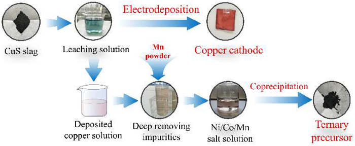
The technological process of preparing cathode copper and ternary precursor from CuS slag powder can be roughly divided into the following four stages (Fig. 1): acid leaching-selective electrodeposition of copper-deep impurity removal-regeneration of the ternary precursors.

|
Download:
|
| Fig. 1. Technological process of preparing cathode copper and ternary precursor from CuS slag. | |
Stage 1: Acid leaching was performed by adding 100 mL of 2 mol/L H2SO4 and 5 g of CuS in a beaker. The leaching parameters were optimized, including leaching time (4 h, 6 h, 8 h, 10 h, and 12 h), leaching temperature (normal temperature, 60 ℃, 70 ℃, 80 ℃, and 90 ℃) and whether to add H2O2. All acid leaching experiments were carried out in a constant temperature heating agitator. The optimum leaching conditions and leaching rates of Ni, Co, Mn, and Cu were obtained by discussing the results.
Stage 2: Potentiation deposition of leach solution using an electrochemical workstation. The electrochemical deposition conditions were optimized, including deposition voltage (−0.35 V, −0.45 V, −0.55 V, −0.65 V, and −0.75 V), deposition time (0.5 h, 1.0 h, 1.5 h, and 2 h), and other conditions were room temperature and 50 mL of solution.
Stage 3: The solution is divided into three steps to remove impurities: removing iron and aluminum, removing calcium and magnesium, and deep impurity removal. The conditions of removing iron and aluminum are as follows: slowly adjust pH with NaOH, stir reaction at room temperature for 1 h, and filter. Filtrate residue is washed with dilute sulfuric acid of different pH. The removal conditions of calcium and magnesium are appropriate amount of NaF, 70 ℃, stirring reaction 1.5 h, filtration. Conditions for deep removal of impurities are excessive Mn powder, 70 ℃, stirring reaction 1.5 h, filtration. Analyze and test the filtrate at each step.
Stage 4: The refined solution of Ni/Co/Mn salt was obtained by evaporation/ concentration/ cooling crystallization and filtration. According to the molar ratio of Ni: Co: Mn = 5:2:3, an appropriate amount of missing Ni/Co/Mn salt was added. A certain concentration of the salt solution and alkali solution was continuously added into the reaction system at an appropriate flow rate. The process conditions of synthesis were controlled, inert gas was introduced, pH was controlled at about 11, and the reaction was stirred at 70 ℃ for 4 h, drying. The ternary precursor powder was obtained by co-precipitation.
Inductively coupled plasma mass spectrometry (ICP-MS, OPTIMA 8300, Thermo Scientific, USA) was used to determine the metal content of CuS slag digested by H2SO4-H2O2, as well as the content of each metal in the solution obtained at each step. An electrochemical workstation (CHI 760e) with three electrodes (reference electrode saturated calomel electrode, waste copper foil as the working electrode, and platinum network as the counter electrode) was used for Potentiation deposition experiment. The E-pH variation of iron and aluminum removal process was calculated with HSC 6.0 software. XRD (D8 Advance) was used to analyze the phase composition and crystallization degree of experimental materials and products. The experimental materials and products were characterized by scanning electron microscopy (SEM, JEOL JSM 7401) and transmission electron microscopy (TEM, TalosF200X).
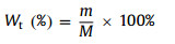
The calculation formula of metal element leaching rate is as follows (Eq. 1):
|
(1) |
where M is the mass of metal ions in CuS slag, and m is the mass of metal ions finally leached from the filtrate after acid leaching.
Cu recovery rate after electrodeposition is calculated as follows (Eq. 2):
|
(2) |
W1 is the change of copper concentration before and after electrodeposition, and W2 is the concentration of Cu in leach solution [23].
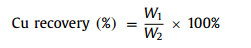
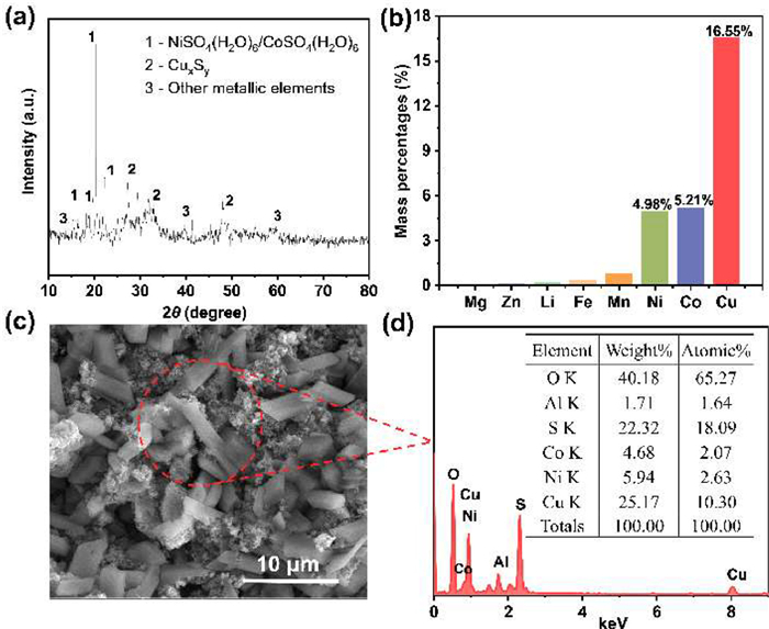
Analysis of CuS slag samples with XRD. the result was shown in Fig. 2a. It is obvious that the phase composition of CuS slag is mainly NiSO4, CoSO4, CuxSy, Mn, Mg, Zn, Al, and other metals are mixed in the solid slag. The chemical composition of CuS slag was analyzed by ICP-MS (Fig. 2b), the contents of Cu, Ni, Co, and Mn were 16.55%, 4.98%, 5.21% and 0.813%, respectively. The content of Al element was 1.543%, and Fe, Li, Mg and other metal elements were all below 0.4% (Table S1 in Supporting information). The above results show that this is a typical battery waste residue, and its main metal element types are basically the same as the ternary lithium battery, which further indicates that this waste residue has potential recycling value.

|
Download:
|
| Fig. 2. (a) XRD patterns of CuS slag. (b) Content of metal elements in CuS slag after digestion (wt%). (c) SEM spectra and (d) EDS of CuS slag. | |
The morphology of CuS slag was characterized by SEM. As shown in Fig. 2c, the micromorphological image of raw material slag, which mainly showed that regular polyhedral structure and irregular flocculent structure. EDS (Fig. 2d and Fig. S2 in Supporting information) results showed that CuS slag clearly contains Cu, Ni, Co, and other metal elements, and the element content is similar to ICP-MS detection results. Therefore, the direct conversion of Cu, Ni, Co, Mn, and other metal ions into battery-grade products using a short-flow in situ enrichment method would be a feasible way to recover CuS slag.
The recovery of valuable metals (Ni, Co, Mn, and Cu) from CuS slag should initially be made to the maximum extent of leaching [24]. As shown in Fig. S3 (Supporting information), the acid leaching conditions were optimized. The maximum leaching rates of Ni, Co, Mn and Cu ions in H2SO4-H2O2 acid leaching system can reach 89.06%, 89.91%, 98.27% and 92.40% at 80 ℃ for 12 h.
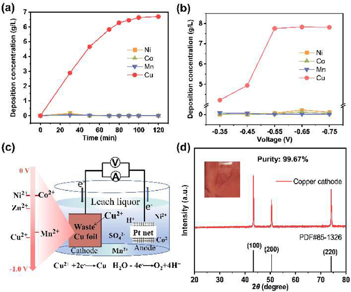
Electrodeposition was used to recover copper ions selectively and efficiently from acid leaching solution (Fig. 3a). With the increase of time, the recovery efficiency of Cu2+ in the acid leaching solution also gradually increased and reached stability after 90 min. After 2 h of electrodeposition, the recovery rate of Cu2+ in the acid leaching solution reached the maximum. Subsequently, in order to further improve the recovery efficiency of Cu, we optimized the electrodeposition voltage. It can be seen from Fig. 3b that when the voltage is −0.55 V, −0.65 V and −0.75 V, the Cu2+ concentration doesn’t change much, but at the same time, in order to minimize the change of other impurity ion concentration, −0.55 V is chosen as the best deposition voltage. Under the optimal conditions, the recovery of Cu2+ in the acid leaching solution reached more than 98% (Table S2 in Supporting information). It is noteworthy that Ni, Co, and Mn exhibit very low deposition concentrations throughout the electrodeposition process, despite their high ionic concentrations. This is attributed to the different redox potentials of the metal elements [25,26]. As shown in Fig. 3c, Cu2+ in solution was deposited on the scrap copper foil by adjusting the reduction working voltage of the cathode.

|
Download:
|
| Fig. 3. (a) Deposition concentration of Ni, Co, Mn, and Cu at different times. (b) Deposition concentration of Ni, Co, Mn, and Cu at different voltages. (c) Schematic representation of selective electrochemical deposition of copper. (d) XRD patterns and purity of cathode copper products. | |
The cathode copper product is reddish brown in appearance, and the product did not dissolve in the acidic solution. XRD was used to analyze the recovered products. As shown in Fig. 3d, the diffraction peaks of cathode copper products obtained by electrodeposition were exactly the same as those of Cu elements in standard card (Cu, PDF#85–1326), with sharp peaks and no other impurity peaks [27]. The results showed that Cu2+ was deposited on the electrode surface in the form of simple copper. The obtained copper cathode product was dissolved and the Cu2+ concentration in it was detected up to 99.67%, and there are almost no impurity ions. Therefore, high purity cathode copper products can be obtained by electrochemical deposition enrichment and selective recovery of Cu in CuS slag, with Cu recovery of over 90% (Table S2). Cu2+ in CuS slag were successfully converted into cathode copper products, which realized the resource recovery of Cu element.
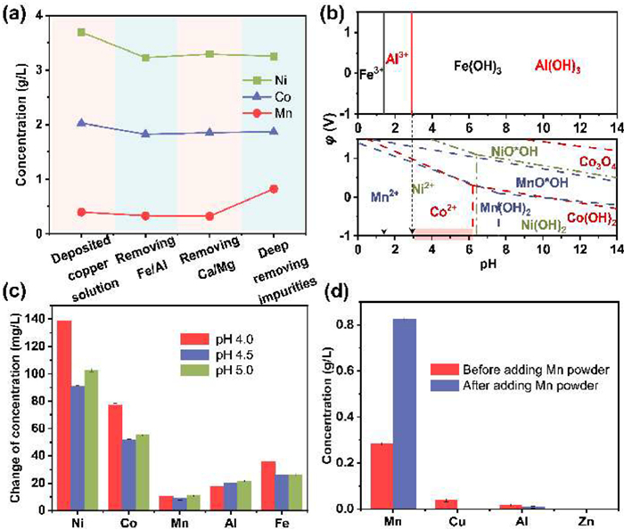
After recovering copper, there were still valuable metals such as Ni, Co, and Mn in the solution. However, some impurities remain (Fe3+, Al3+, Ca2+, Mg2+, etc.) in the solution, so it is necessary to remove impurities from the solution [28]. The change of ion concentration in the whole process of removing impurities is shown in Table S3 (Supporting information), the metal ion impurities are basically removed. From Fig. 4a, Ni, Co, and Mn ions are partially lost in the Fe and Al removal step. In order to increase the recovery of Ni, Co and Mn, we should reduce the loss of the required elements as much as possible. The φ-pH diagram of HSC Chemistry 6.0 software was used to analyze the possible causes of Ni, Co, and Mn ion loss. Fig. 4b shows Fe3+ and Al3+ were completely precipitated in the pH range of 3–6, while there no great overlap between Ni2+, Co2+ and Mn2+ regions. Therefore, the loss of Ni, Co, and Mn ions may be caused by the fact that these ions are removed simultaneously in Fe(OH)3 and Al(OH)3 precipitation due to the local pH is too high during the alkali addition. Therefore, in order to reduce the loss of these critical ions and improve the recovery rates of Ni, Co, and Mn, the removal steps of Fe and Al were optimized in the following experiment.

|
Download:
|
| Fig. 4. (a) The concentration of Ni/Co/Mn ions in the whole process of impurity removal. (b) φ-pH diagram of Fe/Al/Ni/Co/Mn-H2O (25 ℃). (c) The change of concentration of metal ions after washing filter residue with dilute sulfuric acid (4.0, 4.5, 5.0) of different pH. (d) Concentration of metal ions before and after addition of Mn powder. | |
Firstly, the influence of temperature on the change of metal ion precipitation concentration was explored. As shown in Fig. S4 (Supporting information), the results show that the temperature has little influence on the concentration changes of Ni, Co, and Mn ions. Then, the solution pH can significantly adjust the precipitation state of metal ions. According to the φ-pH diagram of Ni, Co, and Mn (Fig. 4b), when pH is less than 6, Ni, Co and Mn exist in the form of ionic state in the solution. Therefore, if the dilute acid at pH 3–6 was used to wash the Fe/Al precipitates, the residual Ni, Co, and Mn metal ions in the precipitates can be dissolved again under the premise that Fe(OH)3 and Al(OH)3 will not be decomposed. From Fig. 4c, it can be seen that the concentration increment of Ni, Co, and Mn metal ions is the largest when pH 4.0, indicating that the loss of Ni, Co, and Mn can be reduced and the recovery of Ni, Co, and Mn ions can be improved by washing the Fe/Al precipitate with dilute acid.
The last step of the process of deep impurity removal is the addition of Mn powder as a removal agent. According to the order of metal activity, Mn may react with impurity metal ions in the solution. The possible reactions of Mn in solution (Eqs. 3 and 4):
|
(3) |

|
(4) |
From Fig. 4d, as a new impurity remover, Mn powder can completely remove the residual impurity Cu2+ in the solution and reduce the concentration of impurity Al3+. More importantly, it also increases the manganese content, thereby increasing the proportion of manganese in the ternary precursor. Therefore, it is an economical and feasible method to use Mn powder as an impurity remover because the cost of raw material is reduced without introducing other impurity ions.
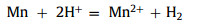
At the end of impurity removal, the metal salt solid of the missing element is supplemented according to the ratio of NCM523, and the refined solution of Ni, Co, and Mn is obtained. The synthesized ternary precursor was characterized and analyzed. The XRD pattern of the regenerated ternary precursor 523 (R-NCM523) is shown in Fig. 5a, where the characteristic peaks correspond to the diffraction peak of the standard NCM523 and has a high consistency. Fig. 5b is the selected area electron diffraction (SAED) patterns of R-NCM523, which clearly shows the orderly lattice arrangement, which indicates the successfully synthesized of R-NCM523. The Fig. 5c shows that the ternary precursor is spherical and granular with dense surface morphology and relatively uniform size. Figs. 5d-g are the element distribution diagrams of R-NCM523, it consistent with TEM plot results (Fig. S5 in Supporting information). It can be clearly seen from the diagrams that Ni, Co, and Mn are evenly distributed in the crystal, which also proves that the ternary precursor has been successfully synthesized. The mass fraction of metal ions in R-NCM523 was detected as shown in Table S4 (Supporting information), which matched the industry standard for NCM523 (WR/WI-SY-30). The rest of the metrics were also in accordance with this technical standard (Table S5 and Fig. S6a in Supporting information). The R-NCM523 was made into a simple battery, and the charge/discharge specific capacity of the material was measured to be above 150 mAh/g (Fig. S6b in Supporting information), which is up to the standard of ordinary commercial batteries. Therefore, the CuS slag generated from recycling ternary cathode materials can be reused through secondary recycling treatment to regenerate NCM523 ternary precursor materials, which better meets the current recycling needs of the lithium battery industry and has high application value [29].

|
Download:
|
| Fig. 5. (a) XRD patterns and (b) SAED patterns (the inset in c is FFT mode) of R-NCM523. Morphological characterization and element distribution of synthesized R-NCM523 particles. (c) SEM image of the R-NCM523. (d-g) Element mapping of O, Mn, Co, and Ni. | |
In order to further understand and evaluate the impact of the process on the environment, the process is compared with the traditional wet process (Fig. S7 in Supporting information), and the carbon emission and energy consumption are studied [30,31]. The source part of raw materials is mainly consumed during transportation process. Therefore, the production of cathode copper and ternary precursor, and the disposal of waste are the main contents of this evaluation. The specific calculation results are shown in Fig. S8 (Supporting information). The carbon emission of raw material transportation is 0.234 kg CO2-eq, and the energy consumption is 3.14 kWh/kg. The carbon emission generated by the recycling process is 2.614 kg CO2-eq, and the energy consumption is 4.867 kWh/kg. The carbon emission from waste treatment is 3.3 kg CO2-eq, and the energy consumption is 1 kWh/kg. This indicates that the experimental process has lower carbon emission and less energy consumption (Figs. 6a and b). Recovery of CuS slag can not only reduce the pollution of heavy metals to the environment, but also reduce the consumption of primary mineral resources. Additionally, from a sustainability point of view, the environmental impact will be mitigated as the consumption of primary mineral resources decreases, leading to a reduction in mining demand [32].

|
Download:
|
| Fig. 6. Comparison of this work with traditional hydrometallurgy in terms of (a) energy consumption and (b) CO2 emissions. (c) Cost, benefit and profit comparisons of this experimental work with traditional hydrometallurgy of copper slag per kg. (d) Radar diagram of economy, energy consumption, CO2 emissions, product purity and process duration of this experimental work compared with traditional hydrometallurgy. | |
In addition to environmental evaluation, the economic benefit of the recovery process was evaluated as well. The total cost of recovering Cu and ternary precursors from CuS slag includes the consumption of raw materials, energy, and reagents. Among them, the reagent refers to sulfuric acid, sodium hydroxide, sodium fluoride, Mn powder, and Ni/Co/Mn metal salt, etc. The detailed cost of treating 1 ton of CuS slag is shown in Fig. S9 (Supporting information). The total cost, profit, and income of the recovery process were compared with traditional hydrometallurgy in Fig. 6c. For this work, the total cost of the recovery process is 0.4388 $/kg, the profit is calculated as 0.5255 $/kg, and the net profit is 0.0867 $/kg. However, the net profit of the traditional hydrometallurgy technology was 0.0308 $/kg by the same calculation. Therefore, the process is economically feasible which has better economic benefits. Finally, the radar diagram shown in Fig. 6d evaluates this work and conventional recycling methods in terms of economy, energy consumption, CO2 emissions, product purity, and process duration. In these five indicators, the design of this work can effectively shorten the process flow, reduce energy consumption, improve the purity of the product, and eliminate environmental pollution. This process has high efficiency and green industrial application prospect, and provides an economical and feasible route for treating the slag of lithium-ion batteries during the recycling process.
In summary, CuS slag was used to prepare high-value cathode copper and valuable ternary precursors through a short-flow in situ enrichment method. The optimal conditions for selective electrodeposition of Cu were as follows: voltage −0.55 V, time 2 h, and the purity of 99.67% copper cathode product was obtained. In the process of impurity removal, washing the precipitate used by dilute acid at pH 4.0 enable reduce the loss of Ni, Co and Mn ions. The impurity was deeply removed after adding Mn powder and achieve the acquisition of Ni/Co/Mn refined solution, and then NCM523 was obtained by co-precipitation. More importantly, through the assessment of its economic and environmental impact, this study provides a practical method for the recovery of valuable metal products from CuS slag.
Declaration of competing interestThe authors declare that they have no known competing financial interests or personal relationships that could have appeared to influence the work reported in this paper.
AcknowledgmentsThis study was financially supported by the Key Project of Research and Development Plan of Jiangxi Province (Nos. 20223BBG74006 and 20201BBE51007), the National Science Foundation of China (No. 52060018), and the National Science Fund for Distinguished Young Scholars (No. 52125002).
Supplementary materialsSupplementary material associated with this article can be found, in the online version, at doi:10.1016/j.cclet.2023.109172.
| [1] |
G. Harper, R. Sommerville, E. Kendrick, et al., Nature 575 (2019) 75-86. DOI:10.1038/s41586-019-1682-5 |
| [2] |
W. Wu, Y. Bai, X. Wang, et al., Chin. Chem. Lett. 32 (2021) 1309-1315. DOI:10.1016/j.cclet.2020.10.009 |
| [3] |
L. Yang, Z. Gao, T. Liu, et al., Environ. Sci. Technol. 57 (2023) 4591-4597. DOI:10.1021/acs.est.3c00287 |
| [4] |
X. Zhong, W. Liu, J. Han, et al., J. Clean. Prod. 263 (2020) 121439. DOI:10.1016/j.jclepro.2020.121439 |
| [5] |
V. Gupta, X. Yu, H. Gao, et al., Adv. Energy Mater. 13 (2023) 2203093. DOI:10.1002/aenm.202203093 |
| [6] |
X. Zeng, J. Li, N. Singh, Environ. Sci. Technol. 44 (2014) 1129-1165. DOI:10.1080/10643389.2013.763578 |
| [7] |
A. Porvali, M. Aaltonen, S. Ojanen, et al., Resour. Conserv. Recycl. 142 (2019) 257-266. DOI:10.1016/j.resconrec.2018.11.023 |
| [8] |
L. Yang, Y. Tu, H. Li, et al., Angew. Chem. Int. edit. (2023) e202308702. |
| [9] |
K. He, Z.Y. Zhang, L. Alai, et al., J. Hazard. Mater. 375 (2019) 43-51. DOI:10.1016/j.jhazmat.2019.03.120 |
| [10] |
D. Song, X. Wang, E. Zhou, et al., J. Power Sources 232 (2013) 348-352. DOI:10.1016/j.jpowsour.2012.10.072 |
| [11] |
Y. Shi, G. Chen, F. Liu, et al., ACS Energy Lett 3 (2018) 1683-1692. DOI:10.1021/acsenergylett.8b00833 |
| [12] |
W. Chu, Y.L. Zhang, X. Chen, et al., J. Power Sources 449 (2020) 227567. DOI:10.1016/j.jpowsour.2019.227567 |
| [13] |
E. Hsu, K. Barmak, A.C. West, et al., Green Chem 21 (2019) 919-936. DOI:10.1039/C8GC03688H |
| [14] |
H. Li, J. Eksteen, E. Oraby, Resour. Conserv. Recy. 139 (2018) 122-139. DOI:10.1016/j.resconrec.2018.08.007 |
| [15] |
L. Miganei, E. Gock, M. Achimovičová, et al., J. Clean. Prod. 164 (2017) 534-542. DOI:10.1016/j.jclepro.2017.06.209 |
| [16] |
P.R. Prem, M. Verma, P.S. Ambily, J. Clean. Prod. 193 (2018) 43-58. DOI:10.1016/j.jclepro.2018.04.245 |
| [17] |
G. Qu, B. Li, Y. Wei, Chem. Eng. J. 451 (2023) 138897. DOI:10.1016/j.cej.2022.138897 |
| [18] |
E. Fan, L. Li, Z. Wang, et al., Chem. Rev. 120 (2020) 7020-7063. DOI:10.1021/acs.chemrev.9b00535 |
| [19] |
P. Zhang, S. Ouyang, P. Li, et al., J. Clean. Prod. 246 (2020) 118728. DOI:10.1016/j.jclepro.2019.118728 |
| [20] |
E.A. Vestola, M.K. Kuusenaho, H.M. Närhi, et al., Hydrometallurgy 103 (2010) 74-79. DOI:10.1016/j.hydromet.2010.02.017 |
| [21] |
W. Utetiwabo, L. Yang, M.K. Tufail, et al., Chin. Chem. Lett. 31 (2020) 1474-1489. DOI:10.1016/j.cclet.2020.01.003 |
| [22] |
D. Zhao, Z. Zhang, X. Tang, et al., Energies 7 (2014) 3121-3135. DOI:10.3390/en7053121 |
| [23] |
K. Liu, J. Yang, H. Hou, et al., Environ. Sci. Technol. 53 (2019) 2748-2757. DOI:10.1021/acs.est.8b06081 |
| [24] |
Y. Liu, W. Lv, X. Zheng, et al., ACS Sustain. Chem. Eng. 9 (2021) 3183-3194. DOI:10.1021/acssuschemeng.0c08163 |
| [25] |
G. Prabaharan, S.P. Barik, N. Kumar, et al., Waste Manage 68 (2017) 527-533. DOI:10.1016/j.wasman.2017.07.007 |
| [26] |
R. Gonçalves, P. Sharma, P. Ram, et al., J. Alloy. Compd. 853 (2021) 157208. DOI:10.1016/j.jallcom.2020.157208 |
| [27] |
L. Wei, J. Li, C. Zhou, et al., Chin. Chem. Lett. 34 (2023) 107893. DOI:10.1016/j.cclet.2022.107893 |
| [28] |
S. Virolainen, T. Wesselborg, A. Kaukinen, et al., Hydrometallurgy 202 (2021) 105602. DOI:10.1016/j.hydromet.2021.105602 |
| [29] |
X. Ma, J. Hou, P. Vanaphuti, et al., Chem 8 (2022) 1944-1955. DOI:10.1016/j.chempr.2022.03.007 |
| [30] |
L.A.W. Ellingsen, G. Majeau-Bettez, B. Singh, et al., J. Ind. Ecol. 18 (2014) 113-124. DOI:10.1111/jiec.12072 |
| [31] |
J. Chen, Z. Wang, Y. Wu, et al., Resour. Conserv. Recy. 146 (2019) 35-44. DOI:10.1016/j.resconrec.2019.03.020 |
| [32] |
Z. Liang, C. Cai, G. Peng, et al., ACS Sustain. Chem. Eng. 9 (2021) 5750-5767. DOI:10.1021/acssuschemeng.1c00942 |