 2024, Vol. 35


b Innovation Laboratory for Sciences and Technologies of Energy Materials of Fujian Province (IKKEM), Xiamen 361005, China;
c The Higher Educational Key Laboratory for Biomedical Engineering of Fujian Province, Department of Biomaterials, Research Center of Biomedical Engineering of Xiamen, College of Materials, Xiamen University, Xiamen 361005, China;
d Key Laboratory of Multifunctional Nanomaterials and Smart Systems, Advanced Materials Division, Suzhou Institute of Nano-Tech and Nano-Bionics, Chinese Academy of Sciences, Suzhou 215123, China;
e Institute of Artificial Intelligence, Xiamen University, Xiamen 361005, China;
f Department of Physics, Research Institute for Biomimetics and Soft Matter, Fujian Provincial Key Laboratory for Soft Functional Materials Research, Jiujiang Research Institute, College of Physical Science and Technology, Xiamen University, Xiamen 361005, China;
g Engineering Research Center of Electrochemical Technologies of Ministry of Education, Xiamen University, Xiamen 361005, China
In the era of advancing information technology, digital circuits have evolved into a pivotal component of contemporary electronic technology, finding extensive application across domains such as computing, communication, control systems, consumer electronics, and medical instruments. In conventional electronics, semiconductor state switching relies on the alteration of electron and hole charge quantities, resulting in substantial energy consumption during information processing and data transmission [1-4]. Within biological systems, ions serve as the charge carriers, facilitating crucial processes such as information transfer, material exchange, and energy conversion through diverse ion channels within membrane proteins situated on the cell membrane [5-8]. Numerous membrane protein pores possess switch-like functionality, constituting vital control hubs within the biological circuit of the cell, akin to the central roles of “diodes and transistors” within microelectronic integrated circuits. The asymmetric characteristics inherent in the structural and chemical composition of distinct channels form the critical material foundation for governing ion channel gating, consequently enabling a multitude of physiological functions [9-12]. Inspired by the biological ion channels, an increasing number of researchers have commenced investigations into the creation of biomimetic asymmetric ion channels and have explored their applications in ionic circuits [13-19].
Currently, a substantial body of research focuses on the modification of responsive molecules on channel surfaces, subsequently using external fields to manipulate the channel's interface properties or its effective dimensions, thereby regulating ion transport [20-26]. For instance, altering external factors such as pH [27,28], concentration [29,30], temperature gradients [31], light and electrical fields [32] to govern interface characteristics like charge and wetting properties in order to modulate ion transport. Additionally, investigations have delved into straightforward mechanically responsive ion channels [33-36], such as the exploration of pressure-dependent ion current rectification in conical-shaped glass nanopores [37,38], and high-density elastomeric channels capable of ultra-mechanosensitive chloride ion transport [39]. Nevertheless, the fabrication techniques for these externally-responsive ion channels rely on costly scientific equipment and intricate material processing steps, thereby constraining progress in current-stage research within the field of ionic devices. Consequently, there is an imperative need for the development of low-cost and straightforward fabrication methodologies. CNTF offer an attractive solution as a macroscopic assembly of carbon nanotubes (CNTs), replete with an intricate network of channels formed by interwoven CNTs, characterized by a high length-to-diameter ratio and mechanical flexibility. This makes CNTF an ideal material for ion channels [40-44].
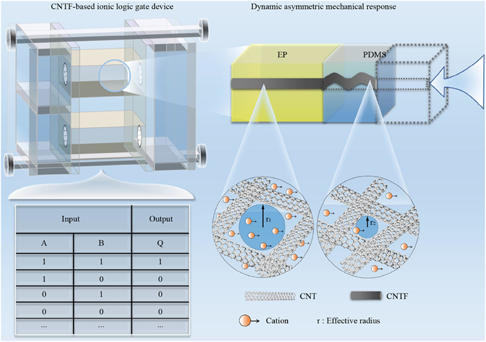
The dynamic asymmetric mechanical response CNTF-based channels with regulatable ion rectification for ionic logic gate devices are revealed in Fig. 1. We composited different polymers on the axis of CNTF. When the mechanical stress was applied to the axis of the CNTF-based channels, due to the different elastic modulus of the polymer at the left (epoxy resin (EP)) and right (polydimethylsiloxane (PDMS)) ends, the CNTF covered in them formed asymmetric deformation. To better understand the mechanism of mechanical stress on ion transport, the channels inside CNTF were idealized. When mechanical stress was applied to CNTF, the effective radius of the channel at the high elastic modulus part (r1) was larger than that at the low elastic modulus part (r2), resulting in the formation of asymmetric channels at the left and right ends, which can adjust the ion transport and made it have a rectification effect. These macroscale asymmetric mechanical response channels can be assembled into an integrated multifunctional logic device, realizing the logic operations of “AND” and “OR”, which shows the potential application in complex highly integrated ionic circuits.

|
Download:
|
| Fig. 1. The scheme of dynamic asymmetric mechanical response CNTF-based materials with regulatable ion rectification for ionic logic gate device. The channels are composed of polymers with different elastic modulus at the left (EP) and right (PDMS) ends of CNTF. Under axial mechanical force, asymmetric deformation occurs at the left and right ends of the channels. The r1 and r2 are the CNTF-based effective radius in high and low elastic modulus, respectively. | |
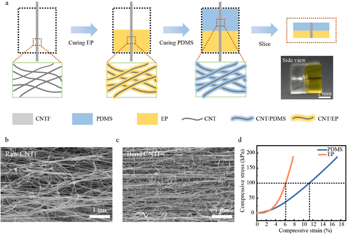
The CNTF can serve as a kind of 1D macroscopic assembly of CNT, which has a high aspect ratio, so it is convenient for axial composite control (Fig. S1a in Supporting information). It also has good mechanical flexibility, as shown in Figs. S1b and c (Supporting information). It can be bent arbitrarily and not broken under hanging weight, so it is suitable for the preparation of ion channels with dynamic mechanical response. The fabrication procedures of the asymmetric CNTF-based channels are shown in Fig. 2a and Fig. S2 (Supporting information), we respectively composite EP and PDMS with CNTF to prepare ion channels (Fig. 2a inset photo). As can be seen from Figs. 2b and c, the diameter of the channel formed by the interlacing of CNTs inside the CNTF after bending is significantly smaller. Therefore, the size of the channel can be regulated by different mechanical stress, so as to realize the construction of the channel with the dynamic asymmetric mechanical response. The EP and PDMS contact angles of CNTF were 56.1° and 51.9°, respectively (Fig. S3 in Supporting information). It was revealed that EP and PDMS have good infiltrability to CNTF, and thus can be well combined on CNTs. The SEM images of CNTF/EP and CNTF/PDMS were shown in Fig. S4 (Supporting information). As can be seen from the EDS characterization and element mapping test, CNTs were covered with EP (Figs. S5 and S6 in Supporting information) and PDMS (Figs. S7 and S8 in Supporting information), and the composite of EP and PDMS was uniform. The two ends of CNTF-based channels were compounded with different polymers. When the compressive stress was applied in the axial direction, the compressive strain of EP and PDMS was different due to their different elastic modulus. It can be seen from Fig. 2d that when the compressive stress was 100 kPa, the compressive strain of EP and PDMS was ~6% and ~11% respectively. Thus, the CNTF wrapped in them can be deformed asymmetrically.

|
Download:
|
| Fig. 2. The preparation and characterization of CNTF-based channels. (a) The fabrication procedures of the asymmetric CNTF-based channels (Inset: photo of CNTF-based channels). SEM images of (b) raw and (c) bend CNTF. (d) The compressive stress curves of PDMS and EP. | |
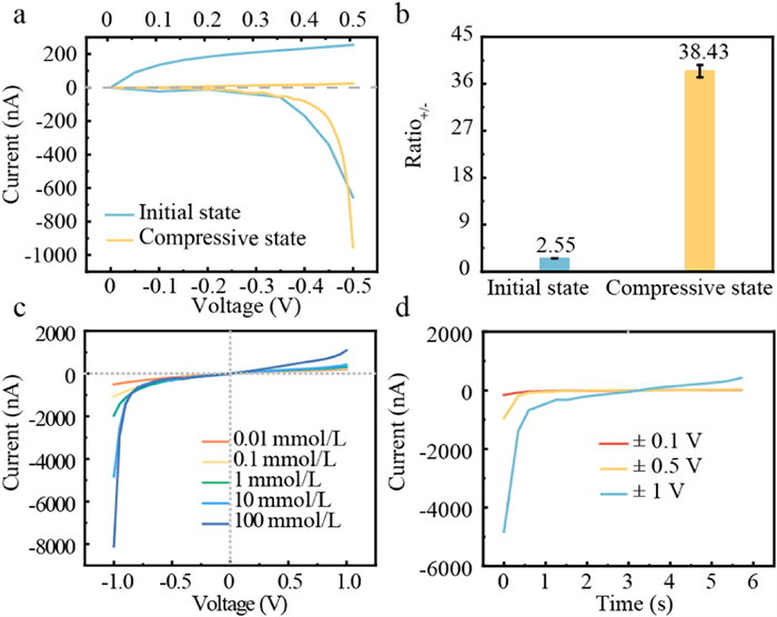
In order to test the ion transport characteristics of CNTF-based channels, a typical I-V curve test was performed and the results were shown in Figs. 3a and b. The ion rectification ratio of the CNTF-based channels before and after compression was 2.55 and 38.43, respectively. The ion rectification of CNTF-based channels after compression was 15 times higher than that before compression (KCl concentration: 10 mmol/L). We hypothesize that the dynamic axial compression would cause the asymmetric deformation of the CNTF-based channels, thereby regulating the ion transport within the channel and improving the rectification effect. To demonstrate the rationality of the dynamic asymmetric mechanical response design and the mechanism, three different composite CNTF-based channels (EP/EP, PDMS/PDMS, and EP/PDMS) were prepared. As can be seen from Fig. S9 (Supporting information), the ion rectification ratio of EP/EP, PDMS/PDMS, and EP/PDMS composite CNTF-based channels after compression were 1.49, 2.37, and 38.43, respectively. It can be seen that only CNTF-based channels that composited different elastic modulus polymers can produce asymmetric deformation after compression and had the highest ion rectification ratio. Therefore, to achieve ion transport regulation of CNTF-based channels under mechanical stress and rectification effect, the difference elastic modulus of polymer which composited at the left and right ends of CNTF is a necessary condition.

|
Download:
|
| Fig. 3. The mechanical responsive properties of CNTF-based channels. (a) The I-V scanning curves of CNTF-based channels before and after compression. (b) The rectification ratio+/− of ion current dependence on the compressive state. (c) The I-V curves of CNTF-based channels at different KCl concentration. (d) The I-T curves of CNTF-based channels at different applied voltages. | |
Considering the effect of the concentration of KCl, applied voltage and electrolytes type on the ion transport in CNTF-based channels, we have optimized these conditions. We have fixed the applied voltage at ± 1 V and changed the concentration of KCl. It can be seen from Fig. 3c and Fig. S10 (Supporting information) that when the concentration of KCl was 10 mmol/L, the ion rectification ratio was the largest, which is 11.32. For concentration, the higher ion concentration brought repulsive interactions while the lower ion concentration brought attractive interactions. Thus, there was an optimum concentration of 10 mmol/L resulting in the best rectification effect [45,46]. Then we fixed the concentration of the KCl (10 mmol/L) and changed the applied voltage. Compared with other applied voltages, when the applied voltage is ±0.5 V, the corresponding rectification ratio is the largest, which was 38.43 (Fig. 3d and Fig. S11 in Supporting information). For applied voltage, it affects the axial ionic concentration distribution and electric potential distribution in the channels, thus, there was an optimum applied voltage (±0.5 V) resulting in the best rectification effect [47,48]. We changed the electrolyte type, and it can be seen from Fig. S12 (Supporting information) that when the electrolyte was KCl, the corresponding rectification ratio was the highest.
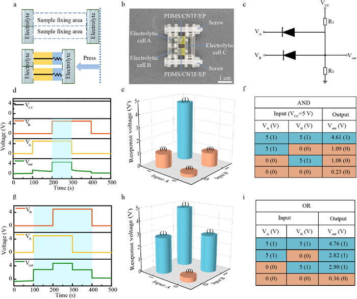
Through the above KCl concentration, applied voltage and electrolytes type, this dynamic asymmetric mechanical response ion channel CNTF-based channels have a good rectification effect, so it can be used as an ionic diode to perform logic functions in ionic devices. As shown in Figs. 4a and b, the ionic logic gate device consists of three electrolytic cells, two sample areas, and two screws. Electrolytic cells A and B were used as inputs for VA and VB, and electrolytic cell C was used as outputs for Vout. Screws were used to fix the two samples in the middle of the electrolytic cells and applied mechanical stress to the samples for the regulation of rectification. The design of simple and highly integrated ionic logic gate device was based on the logic circuit diagram of the “AND” and “OR” gates (Fig. 4c and Fig. S13 in Supporting information). This integrated ionic device can achieve “AND” and “OR” gate function transformation by simply adjusting the orientation of the samples.

|
Download:
|
| Fig. 4. Demonstration of the “AND” and “OR” logic gates. (a) Schematic diagram and (b) picture of logic gate device. (c) Schematic of an “AND” gate integrating two CNTF-based channels ionic diodes. (d) The experimental data, (e) the corresponding logic functions scheme, and (f) the truth table of the input and output signals of the “AND” gate. (g) The experimental data, (h) corresponding logic functions scheme, and (i) the truth table of the input and output signals of the “OR” gate. | |
For the “AND” gate, the experimental input and output signals were shown in Fig. 4d. The “AND” gate contained two resistors in series: R1 =10 MΩ and R2 = 100 MΩ and was powered by a constant Vcc of 5 V. The input and output signals with the status “high” were highlighted with a light blue background, ion “AND” gate realized relatively stable operation similar to the electronic logic circuit. From Figs. 4e and f, we can see that only two high input signals (5 V) can output a high voltage, while the other three cases can only provide a low output voltage. Fig. 4f showed a truth table of an “AND” gate, where the “high” state of the input and output signals was set to the “1” state, highlighted by a dark blue background, while the “low” state was represented by an orange background and a binary number “0” in parentheses. This result demonstrated that the device realizes the “AND” gate function.
For the “OR” gate, the input and output signals with the status “high” were highlighted with a light blue background, from the voltage change curve over time in Fig. 4g, it can indicate the continuous and stable operation of the “OR” gate. In addition, from Figs. 4h and i we can see that only two low input signals (0 V) can output a low voltage, while the other three cases can only provide a high output voltage. Fig. 4i showed a truth table of the “OR” gate, where the “high” state of the input and output signals was set to the “1” state, highlighted by a dark blue background, while the “low” state was represented by an orange background and a binary number “0” in parentheses. This result demonstrated that the device realizes the “OR” gate function.
In conclusion, we have prepared dynamic asymmetric mechanical ion channels by combining EP and PDMS with CNTF. When the mechanical stress was applied to the channel axially, the CNTF covered by EP and PDMS was deformed asymmetrically due to their different elastic modulus, so they had the rectification effect in the process of dynamic compression, the maximum ion rectification ratio was 38.43. The wide range of channel ion rectification ratio (2.46–38.43) can be controlled through the change of KCl concentration and applied voltage. The ion rectification ratio of CNTF-based channels before and after compression can be different by 15 times. Based on this property, we designed a simple and highly integrated logic gate device and integrated the CNTF-based channel in it to realize the basic “AND” and “OR” gate functions. The fabrication method of the dynamic asymmetric mechanical responsive ion channel is straightforward, cost-effective, and versatile, which shows its potential application in complex and highly integrated ionic circuits. For example, the CNTF-based channel can be used as artificial synapses, neuromorphic transistors, biosensors, etc., to achieve human health monitoring, human-computer communication, neuromorphic computing, and various wearable or implantable ionic electronic devices.
Declaration of competing interestThe authors declare that they have no known competing financial interests or personal relationships that could have appeared to influence the work reported in this paper.
AcknowledgmentsThis work was supported by the National Natural Science Foundation of China (Nos. 52273305, 21975209, 52025132, T2241022, 21621091, 22021001, and 22121001), the 111 Project (Nos. B17027, B16029), the Fundamental Research Funds for the Central Universities (No. 20720230037), the National Science Foundation of Fujian Province of China (Nos. 2022J02059, 2023J05012), Natural Science Foundation of Xiamen, China (No. 3502Z20227010), the New Cornerstone Science Foundation through the XPLORER PRIZE.
Supplementary materialsSupplementary material associated with this article can be found, in the online version, at doi:10.1016/j.cclet.2023.109421.
| [1] |
S. Kim, G.W. Baek, J. Jeong, et al., J. Mater. Res. Technol. 12 (2021) 243-256. DOI:10.1016/j.jmrt.2021.02.074 |
| [2] |
Y. Zhao, Q. Li, X. Xiao, et al., ACS Nano 10 (2016) 2193-2202. DOI:10.1021/acsnano.5b06726 |
| [3] |
D. Li, B.A. Wang, M.Y. Chen, et al., Small 13 (2017) 1603726. DOI:10.1002/smll.201603726 |
| [4] |
Q. Cao, M.G. Xia, M. Shim, et al., Adv. Funct. Mater. 16 (2006) 2355-2362. DOI:10.1002/adfm.200600539 |
| [5] |
L. Yang, L. Wen, Cell Rep. Phys. Sci. 3 (2022) 101167. DOI:10.1016/j.xcrp.2022.101167 |
| [6] |
Q. Ma, Y. Li, R. Wang, et al., Nat. Commun. 12 (2021) 1573. DOI:10.1038/s41467-021-21507-7 |
| [7] |
D. Gordon, R. Chen, S.H. Chung, Physiol. Rev. 93 (2013) 767-802. DOI:10.1152/physrev.00035.2012 |
| [8] |
V. Salari, H. Naeij, A. Shafiee, Sci. Rep. 7 (2017) 41625. DOI:10.1038/srep41625 |
| [9] |
Z. Zhang, L.P. Wen, L. Jiang, Chem. Soc. Rev. 47 (2018) 322-356. DOI:10.1039/c7cs00688h |
| [10] |
E. Garcia-Gimenez, A. Alcaraz, V.M. Aguilella, et al., J. Membr. Sci. 331 (2009) 137-142. DOI:10.1016/j.memsci.2009.01.026 |
| [11] |
D.A. Doyle, J.M. Cabral, R.A. Pfuetzner, et al., Science 280 (1998) 69-77. DOI:10.1126/science.280.5360.69 |
| [12] |
B. Su, Y. Tian, L. Jiang, J. Am. Chem. Soc. 138 (2016) 1727-1748. DOI:10.1021/jacs.5b12728 |
| [13] |
C.C. Zhu, Y.F. Teng, G.H. Xie, et al., Chem. Commun. 56 (2020) 8123-8126. DOI:10.1039/d0cc01313g |
| [14] |
Y. Hou, X. Hou, Science 373 (2021) 628-629. DOI:10.1126/science.abj0437 |
| [15] |
J. Hao, W. Wang, J. Zhao, et al., Chin. Chem. Lett. 33 (2022) 2291-2300. DOI:10.1016/j.cclet.2021.10.011 |
| [16] |
J. Yang, Y. Xu, Chin. Chem. Lett. 33 (2022) 2799-2806. DOI:10.1016/j.cclet.2021.09.066 |
| [17] |
L. Yang, P. Liu, C. Zhu, et al., Chin. Chem. Lett. 32 (2021) 822-825. DOI:10.1016/j.cclet.2020.04.047 |
| [18] |
S. Yu, Y. Wang, S. Chatterjee, et al., Chin. Chem. Lett. 32 (2021) 179-183. DOI:10.1016/j.cclet.2020.11.055 |
| [19] |
S. Zhang, I. Boussouar, H. Li, Chin. Chem. Lett. 32 (2021) 642-648. DOI:10.1016/j.cclet.2020.06.035 |
| [20] |
Y. Zhou, J. Hao, J. Zhou, et al., Matter 5 (2022) 281-290. DOI:10.1016/j.matt.2021.11.024 |
| [21] |
K. Xiao, L. Chen, R. Chen, et al., Nat. Commun. 10 (2019) 74. DOI:10.1038/s41467-018-08029-5 |
| [22] |
M. Wang, X. Hou, Joule 7 (2023) 251-253. DOI:10.1016/j.joule.2023.01.012 |
| [23] |
J. Jiang, M.Y. Li, X.Y. Wu, et al., Nat. Chem. 15 (2023) 578-586. DOI:10.1038/s41557-023-01139-8 |
| [24] |
T. Xiong, C. Li, X. He, et al., Science 379 (2023) 156-161. DOI:10.1126/science.adc9150 |
| [25] |
S. Zhang, J. Zhou, H. Li, Angew. Chem. Int. Ed. 61 (2022) e202204012. DOI:10.1002/anie.202204012 |
| [26] |
C. Li, L. Wen, X. Sui, et al., Sci. Adv. 7 (2021) eabg2183. DOI:10.1126/sciadv.abg2183 |
| [27] |
E. Madrid, Y. Rong, M. Carta, et al., Angew. Chem. Int. Ed. 53 (2014) 10751-10754. DOI:10.1002/anie.201405755 |
| [28] |
T.W. Lin, J.P. Hsu, C.Y. Lin, et al., J. Phys. Chem. C 123 (2019) 12437-12443. DOI:10.1021/acs.jpcc.8b11707 |
| [29] |
L. Cao, W. Guo, Y. Wang, et al., Langmuir 28 (2012) 2194-2199. DOI:10.1021/la203837q |
| [30] |
C.Y. Lin, E. Turker Acar, J.W. Polster, et al., ACS Nano 13 (2019) 9868-9879. DOI:10.1021/acsnano.9b01357 |
| [31] |
S. Park, G. Yossifon, Nanoscale 10 (2018) 11633-11641. DOI:10.1039/c8nr02389a |
| [32] |
G. Lu, N. Lin, Z. Chen, et al., Chin. J. Chem. 41 (2023) 1374-1384. DOI:10.1002/cjoc.202200718 |
| [33] |
F.H.J. van der Heyden, D.J. Bonthuis, D. Stein, et al., Nano Lett. 7 (2007) 1022-1025. DOI:10.1021/nl070194h |
| [34] |
T. Mouterde, A. Keerthi, A.R. Poggioli, et al., Nature 567 (2019) 87-90. DOI:10.1038/s41586-019-0961-5 |
| [35] |
S. Marion, A. Radenovic, Nat. Mater. 19 (2020) 1043-1044. DOI:10.1038/s41563-020-00811-5 |
| [36] |
A. Marcotte, T. Mouterde, A. Niguès, et al., Nat. Mater. 19 (2020) 1057-1061. DOI:10.1038/s41563-020-0726-4 |
| [37] |
W.J. Lan, D.A. Holden, H.S. White, J. Am. Chem. Soc. 133 (2011) 13300-13303. DOI:10.1021/ja205773a |
| [38] |
L. Jubin, A. Poggioli, A. Siria, et al., Proc. Natl. Acad. Sci. U. S. A. 115 (2018) 4063-4068. DOI:10.1073/pnas.1721987115 |
| [39] |
C. Li, P. Liu, Y. Zhi, et al., J. Am. Chem. Soc. 145 (2023) 19098-19106. DOI:10.1021/jacs.3c07675 |
| [40] |
J. Di, X. Zhang, Z. Yong, et al., Adv. Mater. 28 (2016) 10529-10538. DOI:10.1002/adma.201601186 |
| [41] |
M. Li, M. Zu, J. Yu, et al., Small 13 (2017) 1602994. DOI:10.1002/smll.201602994 |
| [42] |
X. Zhang, W. Lu, G. Zhou, et al., Adv. Mater. 32 (2020) 1902028. DOI:10.1002/adma.201902028 |
| [43] |
S.H. Lee, J.H. Park, S.M. Kim, J. Korean Ceram. Soc. 58 (2021) 148-159. DOI:10.1007/s43207-020-00106-0 |
| [44] |
Y.K. Zhu, H.J. Yue, M.J. Aslam, et al., Nanomaterials 12 (2022) 3478. DOI:10.3390/nano12193478 |
| [45] |
M. Wang, H. Meng, D. Wang, et al., Adv. Mater. 31 (2019) 1805130. DOI:10.1002/adma.201805130 |
| [46] |
Y. Qiao, J. Lu, W. Ma, et al., Chem. Commun. 56 (2020) 3508-3511. DOI:10.1039/d0cc00082e |
| [47] |
J.F. Pietschmann, M.T. Wolfram, M. Burger, et al., Phys. Chem. Chem. Phys. 15 (2013) 16917-16926. DOI:10.1039/c3cp53105h |
| [48] |
C.Y. Lin, C. Combs, Y.S. Su, et al., J. Am. Chem. Soc. 141 (2019) 3691-3698. DOI:10.1021/jacs.8b13497 |