 2024, Vol. 35


b Key Laboratory of Advanced Display and System Application, Ministry of Education, Shanghai University, Shanghai 200072, China;
c National Key Laboratory of Autonomous Intelligent Unmanned Systems, Tongji University, Shanghai 201804, China
Data processing and storage processes are separated in the traditional von Neumann computer system, which may lead to the bottleneck of computing efficiency when dealing with unstructured data, such as speech and image recognition tasks [1–6]. In contrast, the human brain that contains about 1011 neurons and 1015 synapses has the capability of processing and storing data simultaneously [7,8]. Moreover, these three-dimensional neural networks composed of neurons and synapses in the human brain can process unstructured data more efficiently compared with the von Neumann computer system [9,10]. Therefore, developing the electronics with neuronal and synaptic characteristics is of great significance in the era of today's rapid advancement of artificial intelligence and big data.
Different types of brain-like devices have been explored till now [11–20], among which three/multi-terminal organic electrochemical transistors (OECTs) have attracted extensive attention owing to their similarity with the characteristics of biological neurons and synapses [21–25]. During the operation of OECTs, the ions in the electrolyte can act on the channel layer for modulating the conductivity of OECTs when a gate bias is applied, which is conducive to simulating a series of neuronal and synaptic behaviors. For the dielectric layer of OECTs, two kinds of electrolytes have been explored, namely liquid electrolytes and solid electrolytes. Liquid electrolytes with the characteristic of rapid response to external stimulation can achieve microsecond-level response and operate at the frequency range of tens of thousands of hertz (Hz) [26–28], which are sufficient for recording physiological signals in the biosensing application. However, it is also necessary for liquid electrolytes to consider preservation when applied in complex circuits and practical applications. For example, liquid electrolytes are required to be packaged for preventing the leakage and volatilization of solvents. To deal with this difficulty, stable solid electrolytes composed of organic ion gels are expectantly proposed, which have been extensively employed as the dielectric layer of OECTs [29–34], while most of them have still faced the probability of being damaged by external mechanical forces. As a result, the durability and operation life of OECTs will be reduced, and synchronously the maintenance cost and the amount of discarded electronic components will be increased. Therefore, developing solid electrolytes with self-healing performance is essential for the construction of OECTs with robustness and reliability.
Here, we designed a self-healing polymer electrolyte material by incorporating tris(2-hydroxyethyl)methylammonium methylsulfate ([MTEOA][MeOSO3]) into the composite polymers of poly(2-hydroxypropyl methacrylate) (PHPMA) and poly(ethyleneimine) (PEI). The OECTs were fabricated based on this proposed self-healing polymer electrolyte as the dielectric layer, which successfully simulated important synaptic behaviors, such as excitatory postsynaptic current (EPSC) and paired-pulse facilitation (PPF). Benefitting from the capability of self-healing through dynamic hydrogen bonds in the polymer electrolyte, the electrical properties of the OECTs could still be restored and synaptic behaviors could be entirely emulated even after the dielectric layer was cut in half. Furthermore, simplified neuronal behaviors including both the dendritic integration and sublinear spatial summation were also achieved. More significantly, flexible OECTs were demonstrated based on the self-healing polymer electrolyte, which exhibited almost consistent electrical properties and synaptic behaviors even if the bending radius was reduced to 1 mm, illustrating that our OECTs owned outstanding robustness to external mechanical damages. Therefore, the designed OECTs with self-healing polymer electrolytes have great potential in building neuromorphic computing and wearable electronics in the future.
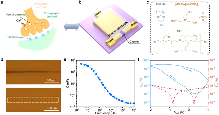
Synapses are the fundamental units in the biological nervous system, which play an important role in transmitting, processing, and memorizing information. Fig. 1a shows a schematic diagram of the synapse. After receiving an electrical impulse, the presynaptic membrane generates an action potential, enhancing its permeability to calcium ions [21]. Then, calcium ions enter the presynaptic membrane and trigger the release of neurotransmitters into the synaptic cleft. The neurotransmitters diffuse and interact with receptors on the postsynaptic membrane, thereby changing its ion permeability. The postsynaptic current will be generated after ions enter the postsynaptic membrane, thus forming information transmission. Inspired by this, an OECT was demonstrated (Fig. 1b), in which the gate terminal, channel, and ions in the dielectric layer corresponded to the presynaptic membrane, postsynaptic membrane, and neurotransmitters, respectively. The channel layer adopts poly(3, 4-ethylene dioxythiophene): poly(styrene sulfonate) (PEDOT: PSS) doped with [MTEOA][MeOSO3] ionic liquid (Fig. 1c). The morphology and electrical properties of PEDOT: PSS can be modulated by the ion doping of [MTEOA][MeOSO3], which is beneficial for carrier transport [35]. Fig. S1 (Supporting information) shows the morphology and thickness of the channel layer characterized by atomic force microscopy (AFM). The smooth surface and continuous structure of the channel layer ensure good contact with the subsequently deposited dielectric layer. Normally, the PHPMA and PEI blend polymer system that contains many dynamic hydrogen bonds can be served as the polymer electrolyte of OECTs for achieving self-healing characteristic, while these hydrogen bonds in the blend polymer system cannot be readily moved into the channel layer (Fig. 1c) [33]. Therefore, the [MTEOA][MeOSO3] containing hydroxyl groups was skillfully added into the PHPMA and PEI blend polymer system, which increased the number of ions that can migrate to dope the channel. X-ray photoelectron spectroscopy (XPS) was employed to characterize the [MTEOA][MeOSO3] in the polymer electrolyte. The obtained sulfur (S) 2p spectrum indicated the presence of the S element in the [MTEOA][MeOSO3] (Fig. S2 in Supporting information). Fig. S3 (Supporting information) displays the Fourier transform infrared (FTIR) spectrum of the polymer electrolyte, which reveals the presence of C=O stretching vibration in the PHPMA at 1721 cm−1, N–H bending vibration in the PEI at 1560 cm−1, and –CH2 symmetric and antisymmetric stretching vibrations at 2848 and 2933 cm−1, respectively. The hydrogen bond of O–H and N–H is confirmed at 3213 cm−1, which is the foundation for the self-healing performance of the polymer electrolyte. Fig. 1d illustrates the self-healing process of the polymer electrolyte with the thickness of about 193 µm (Fig. S4 in Supporting information). A blade was used to scratch the surface of the polymer electrolyte, creating a wound about 10 µm wide. The scratches vanished after heating the damaged polymer electrolyte for 5 min at 50 ℃, demonstrating its rapid and outstanding self-healing ability. To further explore the self-healing ability of the polymer electrolyte after scratching, the ionic conductivity of the electrolyte was investigated by electrochemical impedance spectroscopy. The polymer electrolyte between the two planar electrodes was completely cut. As depicted in Fig. S5 (Supporting information), the ionic conductivity after self-healing was 2.89 × 10⁻³ S/m, which demonstrated almost no attenuation compared with that before damage (2.98 × 10⁻³ S/m). Besides, an electric double layer with the effective capacitance of 50.57 nF at the frequency of 25 Hz was formed owing to the migration of ions in the polymer electrolyte to electrodes under an electric field (Fig. 1e). The effective capacitance decreased as the frequency of the electric field increased originating from the low ion migration rate in the polymer electrolyte responding to the electric field with high frequency. Fig. 1f and Fig. S6 (Supporting information) depict the transfer and output curves of the OECT, respectively. The device resembled an enhancement-mode transistor that remained off when the VGS was set at 0 V. The contact between the PEI in the polymer electrolyte and PEDOT: PSS induced a redox reaction that converted PEDOT+ to PEDOT0 and compensated PSS− by the amine group of PEI, which resulted in a dedoped process that decreased the conductance of PEDOT: PSS, forming a semiconducting channel with reduced charge transport [36–39]. Besides, as the ionic liquid proportion increased and the PEI proportion decreased, the threshold voltage of the OECT gradually shifted to the positive direction, transforming from an enhancement mode to a depletion mode (Fig. S7 in Supporting information). It should be noticed that synaptic behaviors can be simulated in the off-state of the enhancement-mode transistor, which can further decrease the energy consumption. In addition, with the decrease of the proportion of ionic liquid in the polymer dielectric, the on-state current of the OECT decreased. Therefore, the polymer electrolyte with the mass ratio of ionic liquid to blend polymer component of 50% as the dielectric layer of OECTs in this work.

|
Download:
|
| Fig. 1. (a) Schematic diagram of a biological synapse and (b) the structure of the OECT. (c) Molecular structures of [MTEOA][MeOSO3], PHPMA, and PEI, respectively. (d) Optical microscopy images of the polymer electrolyte after blade scratch and after self-healing. (e) Effective capacitance of the polymer electrolyte at different frequencies ranging from 25 Hz to 106 Hz. (f) Transfer curve of the OECT. | |
Fig. S8 (Supporting information) shows the disconnecting and splicing processes of the gate terminal and channel layer of the OECT, simulating presynaptic and postsynaptic disconnection and reconnection. The electrical performance of the OECT before and after repairing was characterized to verify the self-healing ability of the polymer dielectric. The transfer and output curves of the OECT after self-healing were almost consistent with those before damage, indicating that the transistor characteristics were almost completely restored after repairing (Fig. S9 in Supporting information).
Besides, the synaptic behaviors were also simulated in the OECT. In biological synapses, the EPSC is commonly generated by the influx of positive ions into the postsynaptic membrane upon stimulation. Fig. 2a shows the EPSC behavior induced by applying a negative presynaptic spike to the gate terminal. The EPSC peaked at 5.3 µA after stimulation, and then gradually decayed to the baseline before stimulation, well mimicking the dynamics of the EPSC behavior observed in biological synapses [40]. This resulting behavior can be attributed to the mechanism that under a negative presynaptic spike, positively charged [MTEOA]+ ions are attracted to the gate terminal and negatively charged [MeOSO3]− ions are concurrently injected into the channel layer, which oxidizes PEDOT0 that is previously dedoped by PEI to PEDOT+, thus increasing the source-drain current (IDS) of the OECT. As the presynaptic spike is removed, [MeOSO3]− and [MTEOA]+ ions can be slowly recombined in the electrolyte and restore equilibrium. To further evaluate the emulated synaptic behaviors, the presynaptic spikes with different intensities and widths were also applied to the OECT. As depicted in Figs. 2b and c, ΔEPSC (the change of EPSC) increased with the increase of the presynaptic spike intensity or presynaptic spike width owing to the more anions injected into the channel under the spikes with higher intensity or longer width. More significantly, ΔEPSC could be largely maintained even after two consecutive processes of damage and self-healing to the dielectric layer (Fig. S10 in Supporting information). Besides, to simulate the PPF behavior of biological synapses, two presynaptic spikes with an interval of 100 ms were applied (Fig. 2d). After the first EPSC (A1) was induced by the first presynaptic spike, the ions of the polymer electrolyte could not diffuse back to the equilibrium state before the second presynaptic spike was applied, and thus a larger ΔEPSC was achieved in the second EPSC (A2) induced by the second presynaptic spike. Moreover, the OECT with the channel containing [MTEOA][MeOSO3] and PEDOT: PSS produced a larger A2 amplitude than that produced in the OECT with the channel containing pure PEDOT: PSS alone, indicating that the PEDOT: PSS doped with ionic liquids could be more readily modulated by the polymer electrolyte under the electric field (Fig. S11 in Supporting information). Fig. 2e shows that the PPF index (A2/A1 × 100%) decayed as the spike interval increased, which could be fitted by a double exponential function (Eq. 1)

|
(1) |

|
Download:
|
| Fig. 2. (a) EPSC induced by a single presynaptic spike (−2 V, 100 ms). Regulation of EPSCs by presynaptic spikes with different (b) intensities and (c) widths. (d) EPSCs induced by a pair of presynaptic spikes (−2 V, 100 ms) with an interval of 100 ms. (e) PPF index as a function of spike interval. (f) EPSC gain plotted as a function of presynaptic spike number. | |
where ΔT was the spike interval, and τ1 and τ2 represented the initial fast and slow phase facilitation magnitudes, respectively. After self-healing, τ1 and τ2 were extracted to be 298 and 2976 ms, respectively, which were close to τ1 (310 ms) and τ2 (3364 ms) extracted before damage.
By applying multiple consecutive stimuli rapidly to biological neural pathways, the EPSC amplitude can enhance continuously. As depicted in Fig. S12 (Supporting information), the ΔEPSC gradually increased from −0.41 µA to −19 µA induced by the presynaptic spikes with the increase of the presynaptic spike number from 1 to 100, which illustrated the exceptional regulation for the EPSC amplitude in the OECT. Furthermore, the EPSC gain (ΔAn/ΔA1) as a function of the presynaptic spike number was introduced, where An denoted the EPSC induced by the nth presynaptic spike. As shown in Fig. 2f, a 47-fold gain was attained after the stimulation of 100 spikes. Moreover, the EPSC gain significantly increased as the presynaptic spike frequency increased (Fig. S13 in Supporting information). Notably, the EPSC gains achieved after self-healing were quite similar to those achieved before damage, indicating the excellent self-healing ability and robustness of the OECT (Fig. 2f). Noticeably, this work solely focuses on constructing OECTs based on self-healing dielectric layers, and it is expected to develop fully self-repairing OECTs by utilizing self-healing materials for each component in devices.
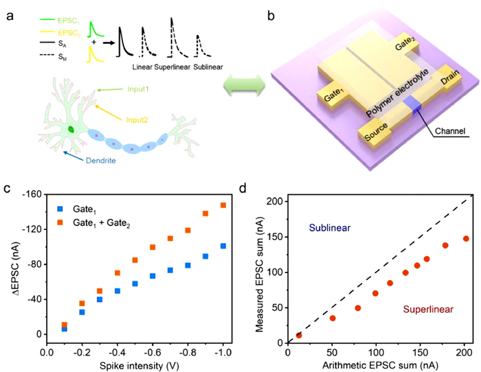
Dendrites are short, branched protrusions in neurons that act as portals for incoming information from other neurons. They receive thousands of impulses from other neurons, which can be integrated and modulated before transmitting to post-synaptic neurons. Spatial summation is the integration of synchronous single events from different regions, while temporal summation is the integration of asynchronous single events [41]. Fig. 3a shows a schematic of the spatial summation of two inputs into a dendrite. The EPSC1 and EPSC2 represent the EPSC triggered by a single presynaptic spike from double gate terminals separately. Their arithmetic sum (SA) is indicated by the black dashed line (EPSC1 + EPSC2), which can be achieved by the summation of the EPSC induced by each presynaptic spike from the single gate terminal of Gate1 or Gate2. The solid black line represents the measured sum (SM) of the EPSC induced by two simultaneous presynaptic spikes from both Gate1 and Gate2 terminals. The superlinear integration is achieved when the SM exceeds the SA (SM > SA). Conversely, the sublinear integration occurs when the SM is smaller than the SA (SM < SA). Fig. 3b illustrates an OECT with an analog spatial summation function, whose Gate1 and Gate2 are symmetrically distributed concerning the channel of the OECT. Fig. 3c shows the ΔEPSCs obtained by the stimulations from single gate terminal and double gate terminals with the increase of presynaptic spike intensity from -0.1 V to -1 V. Obviously, the ΔEPSC obtained by the stimulation from double gate terminals was larger than that obtained by the stimulation from single gate terminal. Fig. 3d plots the SM as a function of the SA, and the result of SM < SA indicates that the spatially sublinear integration can be realized in the in-plane dual-gate OECTs.

|
Download:
|
| Fig. 3. Schematic diagram of the spatial summation of two inputs in (a) a dendrite and (b) the dual-gate OECT. (c) ΔEPSC obtained by applying presynaptic spikes with different intensities on the gate terminal(s) individually and simultaneously. (d) Comparison of the SM and SA of EPSCs. | |
Furthermore, flexible OECTs can be fabricated on a polyethylene terephthalate (PET) substrate with the same structure as the above device (Fig. 4a). The transfer curves of the flexible OECT changed slightly under different bending radii (Fig. 4b). In order to show the comparison of EPSC behaviors under different bending states intuitively, the ΔEPSC and PPF index obtained in the bending state were normalized to those obtained in the plane state. As depicted in Figs. 4c and d, both the induced ΔEPSC and PPF index illustrated almost no attenuation under different bending radii compared with those induced in the plane state, which indicated the outstanding flexibility of the OECT and demonstrated its potential in wearable electronic devices.

|
Download:
|
| Fig. 4. (a) Optical image of the flexible OECT during the bending test. (b) Transfer curves of the flexible OECT under different bending radii. Normalized (c) ΔEPSC and (d) PPF index (normalized to test data in plane state) as a function of bending radius. The standard deviations of error bars were obtained by three independent measurements. | |
In summary, we developed the OECTs based on the self-healing polymer electrolyte as the dielectric layer, which simulated typical synaptic behaviors, dendritic integration of neurons, and spatially sublinear summation. More importantly, after repairing the damage to the dielectric layer, electrical performance of the OECTs and emulated synaptic behaviors could be restored. Furthermore, the flexible OECTs could also maintain almost consistent electrical performance and synaptic behaviors under different bending radii. This work provides promising guidance for advancing flexible and bioimplantable neuromorphic electronics using OECTs with self-healing capability.
Declaration of competing interestThe authors declare that they have no known competing financial interests or personal relationships that could have appeared to influence the work reported in this paper.
AcknowledgmentsThis work was supported by the National Key Research and Development Program of China (No. 2021YFA1101303), the National Natural Science Foundation of China (Nos. 62074111, 62088101), the Science & Technology Foundation of Shanghai (No. 20JC1415600), Shanghai Municipal Science and Technology Major Project (No. 2021SHZDZX0100), and the Innovation Program of Shanghai Municipal Education Commission (No. 2021-01-07-00-07-E00096).
Supplementary materialsSupplementary material associated with this article can be found, in the online version, at doi:10.1016/j.cclet.2023.108582.
| [1] |
R.F. Service, Science 345 (2014) 614-616. DOI:10.1126/science.345.6197.614 |
| [2] |
P.A. Merolla, J.V. Arthur, R. Alvarez-Icaza, et al., Science 345 (2014) 668-673. DOI:10.1126/science.1254642 |
| [3] |
M.A. Zidan, J.P. Strachan, W.D. Lu, Nat. Electron. 1 (2018) 22-29. DOI:10.1038/s41928-017-0006-8 |
| [4] |
D. Kuzum, S. Yu, H.S. Wong, Nanotechnology 24 (2013) 382001. DOI:10.1088/0957-4484/24/38/382001 |
| [5] |
J. Zhang, P. Guo, Z. Guo, et al., Adv. Func. Mater. 33 (2023) 2302885. DOI:10.1002/adfm.202302885 |
| [6] |
Z. Xu, Y. Ni, H. Han, et al., Chin. Chem. Lett. 34 (2023) 107292. DOI:10.1016/j.cclet.2022.03.015 |
| [7] |
D.A. Drachman, Neurology 64 (2005) 2004-2005. DOI:10.1212/01.WNL.0000166914.38327.BB |
| [8] |
X. Wang, D.D. Hao, J. Huang, Sci. China Mater. 65 (2022) 2521-2528. |
| [9] |
J.K. Han, S.Y. Yun, S.W. Lee, et al., Adv. Func. Mater. 32 (2022) 2204102. DOI:10.1002/adfm.202204102 |
| [10] |
Q. Zhang, T.Y. Jin, X. Ye, et al., Adv. Func. Mater. 31 (2021) 2106151. DOI:10.1002/adfm.202106151 |
| [11] |
C. Jin, W. Liu, Y. Xu, et al., Nano Lett. 22 (2022) 3372-3379. DOI:10.1021/acs.nanolett.2c00599 |
| [12] |
J.Y. Zhang, D.P. Liu, Q.Q. Shi, et al., npj Flex. Electron. 6 (2022) 30. DOI:10.1038/s41528-022-00163-x |
| [13] |
W. Huang, Y. Zhang, M. Song, et al., Chin. Chem. Lett. 33 (2022) 2281-2290. DOI:10.1016/j.cclet.2021.08.086 |
| [14] |
Y. Nie, P. Xie, X. Chen, et al., J. Semicond. 43 (2022) 112201. DOI:10.1088/1674-4926/43/11/112201 |
| [15] |
T. Liu, Q. Lin, Y. Ma, et al., Adv. Optical Mater. 10 (2022) 2201104. DOI:10.1002/adom.202201104 |
| [16] |
C. Jin, W. Liu, Y. Huang, et al., Appl. Phys. Lett. 120 (2022) 233701. DOI:10.1063/5.0092968 |
| [17] |
J. Zhang, Y. Lu, S. Dai, et al., Research 2021 (2021) 7131895. |
| [18] |
S. Wang, H. Chen, T. Liu, et al., Angew. Chem. Int. Ed. 62 (2023) e202213733. DOI:10.1002/anie.202213733 |
| [19] |
H. Chen, L. Lv, Y. Wei, et al., Cell Rep. Phys. Sci. 2 (2021) 100507. DOI:10.1016/j.xcrp.2021.100507 |
| [20] |
J.Y. Zhang, Q.Q. Shi, R.Z. Wang, et al., InfoMat 3 (2021) 904-916. DOI:10.1002/inf2.12198 |
| [21] |
S. Dai, Y. Wang, J. Zhang, et al., ACS Appl. Mater. Interfaces 10 (2018) 39983-39991. DOI:10.1021/acsami.8b15063 |
| [22] |
C. Lubrano, U. Bruno, C. Ausilio, et al., Adv. Mater. 34 (2022) e2110194. DOI:10.1002/adma.202110194 |
| [23] |
S.J. Han, S.L. Yu, S.J. Hu, et al., J. Phys. Chem. C 9 (2021) 11801-11808. |
| [24] |
J.L. Ji, H.W. Wang, R. Liu, et al., Nano Energy 87 (2021) 106116. DOI:10.1016/j.nanoen.2021.106116 |
| [25] |
P.C. Harikesh, C.Y. Yang, D.Y. Tu, et al., Nat. Commun. 13 (2022) 901. DOI:10.1038/s41467-022-28483-6 |
| [26] |
J. Rivnay, S. Inal, A. Salleo, et al., Nat. Rev. Mater. 3 (2018) 17086. DOI:10.1038/natrevmats.2017.86 |
| [27] |
J. Song, H. Liu, Z. Zhao, et al., Sci. Adv. 9 (2023) eadd9627. DOI:10.1126/sciadv.add9627 |
| [28] |
J.T. Friedlein, M.J. Donahue, S.E. Shaheen, et al., Adv. Mater. 28 (2016) 8398-8404. DOI:10.1002/adma.201602684 |
| [29] |
Y. Cao, Y.J. Tan, S. Li, et al., Nat. Electron. 2 (2019) 75-82. DOI:10.1038/s41928-019-0206-5 |
| [30] |
D. Liu, Q. Shi, S. Dai, et al., Small 16 (2020) e1907472. DOI:10.1002/smll.201907472 |
| [31] |
Y.W. Liu, Y.F. Wang, X. Li, et al., Chin. Chem. Lett. 34 (2023) 107842. DOI:10.1016/j.cclet.2022.107842 |
| [32] |
R. Granelli, I. Alessandri, P. Gkoupidenis, et al., Small 8 (2022) e2108077. |
| [33] |
W. Huang, K. Besar, Y. Zhang, et al., Adv. Funct. Mater. 25 (2015) 3745-3755. DOI:10.1002/adfm.201404228 |
| [34] |
M. Zabihipour, R. Lassnig, J. Strandberg, et al., npj Flex. Electron. 4 (2020) 15. DOI:10.1038/s41528-020-0078-9 |
| [35] |
T. Li, J.Y. Cheryl Koh, A. Moudgil, et al., ACS Nano 16 (2022) 12049-12060. DOI:10.1021/acsnano.2c02191 |
| [36] |
S.T. Keene, A. Melianas, Y. van de Burgt, et al., Adv. Electron. Mater. 5 (2018) 1800686. |
| [37] |
Y. Xuan, M. Sandberg, M. Berggren, et al., Org. Electron. 13 (2012) 632-637. DOI:10.1016/j.orgel.2011.12.018 |
| [38] |
Y. van de Burgt, E. Lubberman, E.J. Fuller, et al., Nat. Mater. 16 (2017) 414-418. DOI:10.1038/nmat4856 |
| [39] |
S.T. Keene, T.P.A. van der Pol, D. Zakhidov, et al., Adv. Mater. 32 (2020) e2000270. DOI:10.1002/adma.202000270 |
| [40] |
J.R. Yu, Y.F. Wang, S.S. Qin, et al., Mater. Today 60 (2022) 158-182. DOI:10.1016/j.mattod.2022.09.012 |
| [41] |
C.J. Wan, L.Q. Zhu, Y.H. Liu, et al., Adv. Mater. 28 (2016) 3557-3563. DOI:10.1002/adma.201505898 |