 2024, Vol. 35


b College of Chemistry and Chemical Engineering, Hubei University, Wuhan 430062, China
Photocatalytic overall water splitting is considered as one of the most important and attractive green hydrogen production methods to solve the global energy demand. The photocatalytic reaction of splitting water into hydrogen and oxygen through solar energy has received widespread attention since it is possible to convert solar energy into promising energy [1-5]. However, the rate of water splitting based on single photocatalyst is extreme slow due to the low energy of visible light, resulting in an extreme low energy conversion efficiency from solar to hydrogen (STH). The most possible form of artificial photosynthesis is the two-step light excitation called "Z-scheme", which mimics the natural light system. Photogenerated holes with strong oxidizing ability and electrons with strong reducing ability are retained in the unique Z-scheme photocatalytic systems. Z-scheme photocatalytic systems are mainly divided into indirect and direct types according to whether electronic media are required [6-8]. One of the most important characteristics of indirect Z-scheme photocatalyst is the Z-scheme transport path of photogenerated carriers, which is realized indirectly by means of electronic medium [9,10]. According to the types of electronic media used, indirect Z-scheme photocatalytic systems are mainly divided into two types, namely, traditional liquid phase systems and all solid Z-scheme systems [11-13]. All solid Z-scheme system employs conductor as electron mediator between the two photocatalysts to promote the charge transform. Direct Z-scheme system relies on the interfacial electric field for charge transform without electron mediator [14-19]. Then the concept of "S-scheme" was proposed to overcome the shortcomings like dynamical repulsion and energy loss which were exposed in Z-scheme systems [20-22].
Enhancing or extending the range of light absorption [23-26], promoting charge separation [27-34], and loading co-catalysts [35-41] are main strategies to improve the performance of photocatalytic water splitting in the Z(S)-scheme systems. The photocatalyst with high light absorption efficiency are the basis of developing Z(S)-scheme photocatalytic water splitting devices. In order to obtain a wider range of light absorption, it is necessary to extend the light absorption of the material to the visible band or even the near infrared region. Reducing surface reflection and adopting multiple absorption are effective methods to improve the absorption efficiency. Nano-structure and porous structure can effectively reduce surface reflection, and optical scattering and reflection structure can provide multiple absorption process of light [42-45]. In order to promote Z(S)-scheme photocatalytic water splitting in an efficient and simple way, it is urgent to design a suitable heterogeneous catalyst. Therefore, it is critical of comprehensive understanding of the electronic structure and reactivity of these heterogeneous structures. In the last few years, several photocatalysts have been used to develop Z(S)-scheme technologies using multiple redox media [28,46-52]. Guo et al. successfully constructed boron-doped nitrogen-deficient carbon nitride-based Z(S)-scheme heterojunction with 1.16% of solar-hydrogen energy conversion efficiency for pure water splitting [29]. To deeply understand the physical and chemical processes of catalytic reactions, master the activation mechanism of co-catalysts, and construct the system of hydrogen and oxygen generation co-catalysts are also important to promote Z(S)-scheme photocatalytic water splitting [53-58].
Designing novel outstanding Z(S)-scheme heterojunctions to achieve large-scale practical application is also highly desired. Despite the laudable advances in seeking high-efficiency and robust Z(S)-scheme photocatalytic energy conversion systems in the last few years, the exploration is still at the primary stage. There are numerous challenges to overcome in the exploration of remarkably boosting activity, selectivity and long-time durable Z(S)-scheme systems [59-63]. Compared with modifications on single photocatalyst, the strategies used to polish up the ability of Z-scheme photocatalytic systems will be more effective [64,65]. This review mainly introduces various engineering strategies to improve the photocatalytic water splitting performance of Z(S)-scheme photocatalytic systems. These strategies mainly focus on enhancing or extending the range of light absorption, promoting charge separation, and loading co-catalyst in the mechanism of Z(S)-scheme systems. Finally, the main challenges of Z(S)-scheme heterojunctions and their future development directions are pointed out. This review would be beneficial to understand the challenges and opportunities faced by the research field of Z(S)-scheme photocatalytic reaction system, and has important guiding significance for the development and utilization of high-performance Z(S)-scheme photocatalytic system in the future.
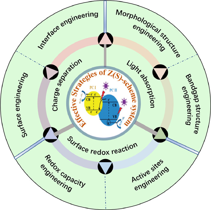
2. Various strategiesThe working mechanism of Z(S)-scheme heterojunction in photocatalytic hydrogen production and oxygen production is mainly divided into three steps- light absorption, charge separation and surface redox reaction [43,66-68]. Therefore, as shown in Fig. 1, the strategies to promote Z(S)-scheme photocatalytic water splitting should focus on enhancing or extending the range of light absorption, promoting charge separation and enhancing surface redox reaction in the working mechanism of Z(S)-scheme photocatalytic water splitting systems [69-76]. The energy of sunlight is mainly concentrated in the visible and infrared regions, in which the proportion of visible light is about 43% and the proportion of infrared light is 53%. Therefore, the development of visible light or even infrared light response photocatalysts is of great significance for the full utilization of solar energy [77-79]. In order to improve the efficiency of Z(S)-scheme photocatalytic water splitting, it is necessary to develop catalytic materials with high light absorption efficiency.

|
Download:
|
| Fig. 1. Various strategies to promote Z(S)-scheme photocatalytic water splitting systems (PC Ⅰ: Photocatalyst Ⅰ for reduction; PC Ⅱ: Photocatalyst for oxidation). | |
In the working process of the Z(S)-scheme system, the first significant step is the light absorption. Hence, how to enhance the ability of the light absorption in the Z(S)-scheme system is a common dimension to polish up the capacity for overall water splitting. Morphological structure engineering and bandgap structure engineering are the most effective strategies to strengthen the light absorption of the Z(S)-scheme system. Here we will list several examples to show the strategies for improving the efficiency of the Z(S)-scheme system in the way of morphological structure engineering and bandgap structure engineering.
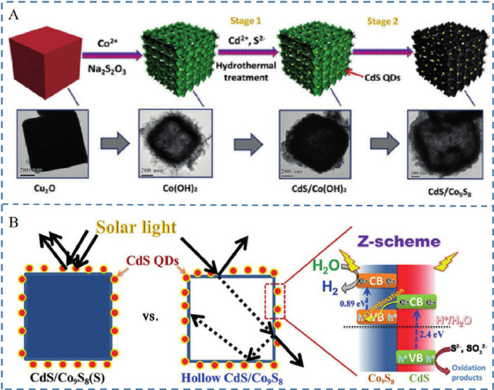
2.1.1. Morphological structure engineering in Z(S)-scheme systemThe design of the morphological material structure can promote light absorption of semiconductors that make up heterojunctions to improve the Z(S)-scheme photocatalytic performance. Hollow cubes have the characteristic of exhibiting anisotropic shapes which exposing more edges and faces to fully absorbs light energy by multiple scattering. Therefore, Qiu et al. proposed an idea that the use of Co9S8 hollow cube is a splendid application for the construction of a redox-mediator-free Z-scheme system [25]. Fig. 2A shows the design and synthesis of a Co9S8 hollow cube modified by CdS quantum dots. Using dimethyl sulfoxide (DMSO) as the solvent and hollow Co(OH)2 cube as the template, a simple hydrothermal method was used to obtain a hybrid Z-scheme system. A "mediatorless" Z-scheme photocatalytic system is directly constructed by loading CdS quantum dots on the surface of the Co9S8 hollow cube. TEM images clearly show that highly dispersed CdS/Co9S8 hollow cubes were successfully prepared. Due to the excellent advantages of hollow structure, the multiple reflections after the preparation of the CdS/Co9S8 hollow cubes for the Z-scheme system is illustrated in the Fig. 2B. Hollow structures allow lights to be more scattered and refracted compared to solid structures. The hollow CdS/Co9S8 hollow cube exhibits efficient solar light collection capabilities due to multiple scattering and refraction, making the Z-scheme system exhibit incredible HER activity and stability under sunlight. Taking advantage of the high position of the Co9S8 conduction band and the large electron reduction potential, fully combined with the "light multiple reflection" effect of the hollow structure, the strong interfacial force between CdS and Co9S8 promotes the transfer of CdS conduction band electrons to the Co9S8 valence band in the absence of a mediator, effectively inhibits the occurrence of photogenerated charge inverse reaction and improves the activity and stability of the catalyst.

|
Download:
|
| Fig. 2. (A) The preparative process for CdS/Co9S8 and corresponding TEM images; scale bar (200 nm). (B) Illustration of multiple reflections within the CdS/Co9S8 hollow structure and the photoexcited charge-carrier distribution. Reprinted with permission [25]. Copyright 2017, Wiley-VCH Verlag GmbH & Co. KGaA, Weinheim. | |
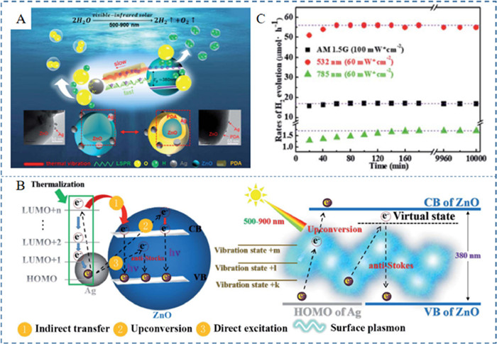
The semiconductor photocatalysts used in the Z(S)-scheme system are limited by their inherent energy band characteristics and only respond to specific wavelength photons. It is urgent to develop photocatalysts that can absorb visible and near-infrared light to improve the separation efficiency of photogenerated electron-hole pairs in the Z(S)-scheme system. Therefore, Xue et al. use the local surface plasmon resonance effect (LSPR) of noble metal nanoparticles to achieve large-scale solar spectral absorption and significantly extend the plasmon lifetime by designing the polydopamine passivation layer [26]. Fig. 3A shows a plasma layer-passivated ternary particle photocatalytic water separation system. The system includes light-harvesting antennas, oxygen evolution active sites (Ag clusters), surface passivation layer (PDA) and hydrogen production active sites (ZnO). The Ag node is embedded in the PDA and the connection between the PDA and Ag node are non-covalent bonds. Some Ag atoms clump together to maintain a strong LSPR effect. The passivation effect of PDA is an enhancement of the thermodynamics and kinetics of the plasma system. The thermal vibration induced reverse transfer process lasts much longer than the LSPR excitation process in the presence of PDA passivation layer. As a result, the excited electrons and holes can continue to respectively accumulate and participate in subsequent HER and OER reactions. Fig. 3B illustrates the thermodynamic electron transfer mode of the system. Path 1 corresponds to the indirect transfer process between Ag and ZnO, and although this path satisfies the laws of thermodynamics, only a few electrons will eventually be transferred to the CB of ZnO. Therefore, a more efficient up-conversion mechanism in path 2 is particularly important to compensate for the lack of electron transfer in path 1. Path 3 transfers electrons directly to the Raman virtual state of ZnO through the high vibrational energy level of the plasma exciton. The catalytic activity of the system is significantly enhanced under the joint action of the three pathways. The results of Fig. 3C confirm the excellent catalytic activity and stability of the system. Under the 532 nm light source, the deactivation rate of the carrier was balanced with the generation rate at about 60 min, under 785 nm it was about 170 min, and under AM 1.5 G it was about 70 min. The performance of the material remained stable after continuous catalysis for 10,000 min. The energy pool effect of the PDA passivation layer can greatly extend the charge lifetime generated by the plasma exciton, thus solving the problem of time mismatch between the plasma exciton and numerous physical/chemical process.

|
Download:
|
| Fig. 3. (A) The experimental system and schematic illustration of Ag-PDA/ZnO for water splitting in the visible-infrared solar irradiation. (B) The schematic illustration for plasmonic upconversion and direct excitation. (C) The stability test of Ag-PDA/ZnO. Reprinted with permission [26]. Copyright 2022, Chemistry A. Royal Society of Chemistry. | |
After the first step of light absorption in the working process of the Z(S)-scheme system, the second key factor of the system is the speed of charge separation. The fast charge transfer rate of Z(S)-scheme system significantly inhibits the recombination of photoinduced electron-hole pairs, thereby improving the separation efficiency of effective carriers [80-82]. The separation of carriers can promote the spatial separation of reducing and oxidizing active sites, ensuring that specific photocatalytic reactions can take place on the corresponding active sites. Also, conjugated skeleton structures of the porous organic and organic-inorganic hybrid materials are beneficial for the transport of reactants and carriers in the Z(S)-scheme systems. In general, the main strategies to promote the charge separation in the Z(S)-scheme system can be divided into two types: surface engineering of the photocatalysts and interface engineering between the photocatalysts.
2.2.1. Surface engineering in Z(S)-scheme systemOn the surface of photocatalysts, uncontrollable charge recombination reactions are the main factors leading to the low efficiency of Z(S)-scheme photocatalytic systems. The two uncontrollable back electron transfer processes as shown by red arrows in Fig. 4A would induce the poor efficiency of the energy conversion. Fig. 4A clearly shows the mechanism of charge transfer in the Z(S)-scheme for overall water splitting. Therefore, how to suppress these two back electron transfer reactions has become a major challenge to improve the efficiency of the Z(S)-scheme photocatalytic system. Al2O3 and anionic polystyrene sulfonate polymer (PSS) were used to modify the surface of the dye-sensitized photocatalyst to inhibit the reverse reaction process in Fig. 4B. On the one hand, the back electron transfer reaction (I3– + e– → I– + I2) was suppressed due to the electrostatic repulsion between the anionic polymer of PSS. On the other hand, Al2O3 can inhibit the reverse electron transfer reaction from oxide to adsorption dyes. The difference in Z(S)-scheme activity among the differently modified nanosheet photocatalysts was found to be much clearer when the Z(S)-scheme reactions were conducted under simulated sun-light. Fig. 4C exhibits STH energy conversion efficiencies under different light intensity conditions using different samples. It is clear that the STH of the modification with Al2O3 and PSS increasing nearly a hundredfold compared with the original Ru/Pt/HCa2Nb3O10 nanosheets. The STH of the optimized system is 0.12% which is the highest value in the modified way of the surface-modified and dye-sensitized nanosheets solar-driven Z(S)-scheme for overall water splitting. This work will lead the development of dye-sensitized photocatalysts as solar energy conversion materials and are also expected to promote the development of this field.

|
Download:
|
| Fig. 4. (A) Electron transfer mechanism. Schematic electron transfer mechanism and energy level diagram of the Ru/Pt/HCa2Nb3O10 nanosheets for H2 evolution and PtOx/H—Cs-WO3 for O2 evolution. (B) Schematic reaction mechanism of PSS/Ru/Al2O3/Pt/HCa2Nb3O10 nanosheets during visible-light H2 evolution. (C) STH energy conversion efficiencies of Ru/Pt/HCa2Nb3O10 nanosheets with different modifications for Z-scheme water splitting. Reprinted with permission [27]. Copyright 2022, American Association for the Advancement of Science. | |
Multi-mediator modulation is one of the significant measures in surface engineering to promote the overall water splitting performance of Z(S)-scheme system. Based on the principle of natural photosynthesis, Li et al. successfully realized the highly efficient photocatalytic overall water splitting process inspired by the Z(S)-mechanism of natural photosynthesis by adopting a multi-media regulation surface engineering strategy [28]. By coupling inorganic oxide based photoanodes and organic-polymer based photocathodes with multiple charge transfer media, a photoelectrochemical cell for efficient unbiased overall water splitting was assembled as shown in Fig. 5. It is found that the organic polymer in this system has discrete energy level characteristics, which makes the spectral absorption of organic photocathode and inorganic photocathode complementary, and greatly improves the utilization of solar energy. In addition, in the system, a bionic charge transport chain containing multiple charge transport media was constructed between the light harvesting material and the electron acceptor/donor. Driven by the electrochemical potential gradient, photogenerated electrons transfer effectively through these charge transfer media, which improves the charge transfer rate and reduces the charge recombination rate, thus achieving efficient charge separation and transmission. Therefore, the solar hydrogen conversion efficiency reaches 4.3%.

|
Download:
|
| Fig. 5. Schematic diagram of natural photosynthesis and the photoelectrochemical platform with multi-mediator modulation. Reprinted with permission [28]. Copyright 2021, American Chemical Society. | |
Photogenerated charge separation is the core scientific problem of artificial photosynthetic solar fuel on the surface of photocatalysts. The design and development of efficient photogenerated charge separation strategies to promote the separation and transmission of photogenerated charges has always been a hot spot and difficulty in this research field. Wang et al. found that the polarity-induced surface electric field effectively promoted the spatial separation of photogenerated charges, which could greatly improve the activity of Z(S)-scheme photocatalytic overall water splitting [33]. To realize the improvement of the system, the preparation process of the semiconductor gallium nitride (GaN) system was shown in Fig. 6A. The GaN nanorod array structure with clear surface polarity qualities was prepared by metal-organic vapor deposition method. The array structure exposes the polar planes at the top and the non-polar surfaces on the vertical side, respectively. From the working mechanism of the system, the GaN nanoarray structures exhibit significant photogenerated charges separation characteristics between the polar and non-polar surfaces. Photogenerated electrons selectively gather on the non-polar surface of the nanorod while photogenerated holes gather on the polar surface. Fig. 6B shows the photogenerated charge separation efficiency of GaN nanorods with polar and non-polar surfaces exceeds 80% via further discovery by photoelectron-chemistry and photocatalytic reaction characterization, which is more than ten times higher than the charge separation efficiency of GaN films. The performance of the system has the highest charge separation efficiency reported by similar materials. The amounts of hydrogen production and oxygen production were presented in Fig. 6C. The optimized system not only has high reactivity but also has long-term chemical stability. This work proposes a new strategy of universal photogenerated charge separation which lays a theoretical foundation for the construction of an efficient artificial photosynthesis system. Meanwhile, it also provides new ideas for further deepening the understanding of the essential driving forces of photogenerated charge separation.

|
Download:
|
| Fig. 6. (A) Schematic representation of Z-scheme process in the semiconductor gallium nitride (GaN) system. (B) The corresponding quantum efficiency of oxygen evolution reaction (OER) and hydrogen evolution reaction (HER). (C) Multi-cycles of photocatalytic OWS on the Rh-CoOx/GaN nanorod arrays. All the photocatalytic reactions were conducted under illumination of 300-W Xe lamp. For comparison, the activities were normalized to that on 1 cm2 of GaN wafer. Reprinted with permission [33]. Copyright 2020, John Wiley & Sons. | |
The idea of building cascade charge transfer and single-atom catalytic sites on the surfaces of photocatalysts can not only facilitate the charge transfer but also provide active sites in the working process of Z(S)-scheme system. Peng et al. used graphene oxide as a template to prepare BiVO4 nanosheets (NSs) with a thickness of ~3.76 nm by hydrothermal method [34], and then deposited a layer of Zn/Pt heterometallic monoatomic porphyrin based on polymer with a thickness of ~1.26 nm on its surface in situ to construct a new two-dimensional composite as shown in Fig. 7A. Photogenerated charge transfer mechanism of this composite was proved to be Z(S)-scheme by means of photoelectrochemical properties, active species detection and near edge absorption. In ZnPtP-CP/BiVO4 composite, BiVO4 NSs and ZnPtP-CP polymer are in close contact at the interface through Zn-O-V bond bridging. The excellent apparent quantum yield (9.85%) was obtained at 400 nm. The highly efficient overall water splitting performance of ZnPtP CP/BiVO4 is mainly attributed to its unique structural characteristics. First of all, the BiVO4 NSs prepared with a large number of exposed (010) crystal faces have a large specific surface area, which not only provides a large number of active sites for the photocatalytic reaction, but also enables them to closely contact with the ZnPtP-CP polymer at the interface, thus accelerating the transfer efficiency of photoelectrons. Secondly, the ultra-thin BiVO4 NSs effectively shortens the migration distance of internal photogenerated electrons to its surface, hinders the recombination of photogenerated charges, and promotes the separation of photogenerated charges in the photocatalytic system along the two-step excitation Z(S)-scheme path. In addition, type Ⅱ heterojunction will be formed between two adjacent porphyrin molecules in the ZnPtP-CP polymer, that is, type Ⅱ heterojunction arrays are periodically distributed in the ZnPtP-CP. Fig. 7B is the band structure of the Z-scheme water splitting system. In the process of photocatalysis, the photogenerated electrons are transferred from BiVO4 NSs to the ZnPorBr core of ZnPtP-CP, and then transferred to the PtPorF core in ZnPtP-CP for the reduction reaction of water, while the holes finally remain on BiVO4 NSs for the oxidation reaction of water. The improvement of the Z-scheme water splitting performance is shown in the Fig. 7C. It is apparent to find that the catalytic activity of the system is optimal when 20wt% ZnH2P-CP /BiVO4. This highly ordered electron transport path enables a more efficient electron utilization efficiency than traditional Z(S)-scheme catalysts, so as to achieve an efficient Z(S)-scheme charge separation mechanism for overall water splitting without sacrificing agents or external bias. The results of this study provide a way for the construction of Z(S)-scheme bifunctional photocatalysis system based on monatomic active sites.

|
Download:
|
| Fig. 7. (A) Schematic diagram of the synthesis route, structure and charge transfer mechanism of the ZnPtP-CP/BiVO4 composite. (B) Schematic diagram of energy band structures and direct Z-scheme mechanism of the ZnPtP-CP/BiVO4. (C) Overall water splitting performance of various samples under the optimized photocatalytic reaction condition. Reprinted with permission [34]. Copyright 2021, John Wiley & Sons. | |
2D/2D polymeric heterostructure is an ideal structure to build a splendid interface for the charge transform and separation. Due to the thermodynamic contradiction between light absorption and redox potential, the development of one-component photocatalytic Z(S)-scheme systems for overall water splitting still faces great challenges. Zhao et al. used ultra-thin g-C3N4 (CNN) to achieve photocatalytic hydrogen evolution reaction, and then used g-C3N4 (BDCNN) containing boron doping or nitrogen defects to adjust the band structure to achieve photocatalytic oxygen evolution reaction [29]. By combining these two catalysts, a Z(S)-scheme heterostructure system can be formed to achieve photocatalytic water splitting. The schematic of the synthesis of BDCNN derived from CNN was shown in Fig. 8A. First, ultra-thin g-C3N4 (CNN) is prepared by two-step method of ultrasound-calcination. Then, the rapid heating treatment was carried out for CNN by NaBH4 to obtain g-C3N4 with boron doping and nitrogen defects (BDCNN). Both of the CNN and BDCNN are ultra-thin nanosheets with a thickness of only about 1 nm. In Fig. 8B, the CNN and BDCNN were assembled together to build Z(S)-scheme heterostructure system through electrostatic self-assembly method. When the mass ratio of CNN to BDCNN is 1:1, the ratio of hydrogen and oxygen producing achieve about 1:1 and the best photocatalytic activity was realized. The mechanism of Z(S)-scheme heterostructure was illustrated in Fig. 8C. The Z-scheme heterostructure constructed by CNN in combination with BDCNN provides an interface for more effect charge separation and transfer. Meanwhile the photogenerated electrons and photogenerated hole diagrams of hydrogen and oxygen-producing photocatalysts in the carbon nitride Z(S)-scheme heterostructure have a high enough energy barrier to drive the water reduction and oxidation reaction to achieve photocatalytic decomposition of pure water to produce hydrogen and oxygen. Owning to the advantages of ultra-thin nanostructures, strong interfacial interactions and interlaced band arrangement, the water-splitting performance of the system behaves well in Fig. 8D.

|
Download:
|
| Fig. 8. (A) Schematic of the synthesis of BDCNN derived from CNN. (B) Schematic of the synthesis of the CNN/BDCNN heterostructure. (C) Schematic of the Z-scheme charge-transfer route in the CNN/BDCNN heterostructure. (D) The overall water-splitting performance of different Z-scheme heterostructures (40 mg), self-assembled from one H2-evolving component (CNN, BDCNN325, BDCNN350 or BDCNN375) and one O2-evolving component (BDCNN400, BDCNN450 or BDCNN500), under UV–visible light irradiation (λ > 300 nm). Measurements were taken at least three times for separate samples and average values are presented with the standard deviation as the error bar. Reprinted with permission [29]. Copyright 2021, Springer Nature Limited. | |
Since the large band gap of the CNN will inhibit the photocatalytic activity, Zhao et al. chose BDCNN with a narrower band gap as the hydrolytic photocatalyst in combination with another BDCNN as an oxygen evolution component to build the structure of the Z(S)-scheme system [29]. The band structures of g-C3N4 could be rationally modulated with the simultaneous introduction of boron dopants and nitrogen defects by thermal treatment with NaBH4 at different temperatures. Through the optimization of the band structure, the photocatalytic activity of the synthesized Z-scheme heterostructure has been greatly improved. With the addition of Pt and Co(OH)2 co-catalysts, hydrogen production and oxygen production rates reached 62.69 µmol/h and 31.12 µmol/h. Solar to hydrogen conversion efficiency (STH) reached 1.16% under simulated sunlight exposure. The breakthrough of the measure confirms that highly active hydrogen and oxygen-producing photocatalysts can be obtained simultaneously by fine-tuning the band structure of interface between polymer semiconductors and used to construct Z(S)-scheme heterostructures based on homologous substances. The construction of Z-scheme heterostructures is of great significance for achieving efficient photocatalytic splitting of water. However rationally regulating Z-scheme charge transfer to improve energy transfer efficiency remains a huge challenge. Building interfacial chemical bond and internal electric field between the PC I and PC II is also a fantastic method to promote the charge separation. Wang et al. synthesized ZnIn2S4 and MoSe2 consisting of S vacancies to act as the Z(S)-scheme heterostructure. Z(S)-scheme interface Mo-S bond and internal electric field can be regulated for efficient photocatalytic hydrogen evolution [30].
In Fig. 9A, hydrazine monohydrate (N2H4·H2O) was added to create S vacancies and unsaturated coordinative S atoms. The S vacancy enhances light absorption and promotes photocarrier separation, while the abundant coordination unsaturated S atoms can act as anchor for Mo atoms, thereby promoting the formation of Mo-S bonds and the in-situ growth of MoSe2 on the surface of Sv-ZIS. The introduction of anionic vacancies in semiconductors not only enhances the light absorption capacity of the original semiconductor, but also introduces an intermediate gap state in the band gap as an effective electron "trap" to accelerate the separation efficiency of photocarriers. Therefore, adjusting the appropriate S-vacancy of ZnIn2S4 is a key factor in ensuring the high activity and stability of the photocatalyst. The Z(S)-scheme diagram of photocatalytic mechanism is shown in Fig. 9B. A large number of photoinduced electrons (e−) with enough energy could transform from the VB of Sv-ZIS to the CB of Sv-ZIS, as a result the holes (h+) on the VB of Sv-ZIS are been left. It is of great significance that the abundant S vacancies inside ZIS could introduce new donor level in the band gap of ZIS, which can work as efficient electrons trap to restrain the photogenerated electron-hole pairs recombination. Also, the electrons on the CB of MoSe2 will transform to the VB of Sv-ZIS to recombine with the holes by the driving power of the internal electric field. The Mo-S bond working as atomic-level interfacial "bridge" has the ability to accelerate the photoexcited carriers migrating between Sv-ZIS and MoSe2. The effect greatly accelerating the charge shift in the Z(S)-scheme system. The H2 evolution rate of different photocatalysts are evaluated in the Fig. 9C. The amount of H2 evolution of original ZIS is extremely low of about only 3.36 mmol g−1 h−1 and the Sv-ZIS rate produces H2 is slightly increased of 4.77 mmol g−1 h−1. The S-vacancy caused by the electron trap accelerating the photocarrier separation improves the photocatalytic performance of Sv-ZIS. Moreover, the introduction of MoSe2 strengthen the H2 evolution of the Sv-ZIS/MoSe2. When the mass ratio of MoSe2 to ZIS reached 5.0%, the H2 precipitation rate reached the highest, which was 63.21 mmol g−1 h−1, 18.8 and 13.3 times higher than that of original ZIS and SV-ZIS respectively.

|
Download:
|
| Fig. 9. (A) Synthesis process. Schematic presentation of the synthetic route of Sv-ZnIn2S4 and Sv-ZnIn2S4/MoSe2 heterostructure. (B) Photocatalytic reaction mechanism of Sv-ZIS/MoSe2 under light irradiation. (C) H2 evolution rate of different photocatalysts. Reprinted with permission [30]. Copyright 2021, Springer Nature Limited. | |
Typically, the construction of Z(S)-scheme photocatalytic systems involves tedious experimental process to provide the area for electronic transform between the two semiconductors [83-91]. Janus-like structures have the capacity to accurately separate the two catalysts and realize charge transfer on the interfaces. Xiong et al. constructed a class of Z(S)-scheme photocatalysts without tedious experimental process based on a facile cation-exchange approach to successfully build the Janus-like structures [31]. In this work, roxbyite Cu7S4 was selected as the starting template because of its high Cu vacancy density. Fig. 10A shows the transition from Cu7S4 to λ-MnS by precisely controlling the time and temperature of cation exchange. Using Cu7S4 nanocrystals as precursors, NC5 samples with Mn/Cu molar ratio of up to 256 were finally obtained by cation exchange synthesis route at high temperatures and long reaction times, which can be roughly regarded as λ-MnS nanocrystals. The Janus-like structure constructed by Cu7S4 and λ-MnS was induced by cation exchange of tetrahedral Mn2+ ions. The electronic band structures of λ-MnS and Cu7S4 was shown in the Fig. 10B. The energy band of Janus-like structure between λ-MnS and Cu7S4 indicates that the Z(S)-scheme photocatalytic system is constructed effectively. In order to investigate the properties of the Z(S)-scheme photocatalytic system, Fig. 10C shows the catalytic performance measured in different spectral regions. It can be clearly seen that under the condition of full spectral irradiation, the photocatalytic hydrogen evolution performance of the Z(S)-scheme system has been greatly improved. Hydrogen evolution rate of NC3 is the most optimal among all the samples. The result clearly indicated the significant role of the Janus-like structure in the construction of Z(S)-scheme system. The progress of this research has opened up a new idea for the design of broad-spectrum photocatalytic materials, and also promoted the surface interface design of composite photocatalysts.

|
Download:
|
| Fig. 10. (A) Cation exchange evolution by precisely controlling the reaction time. the initial roxbyite Cu7S4 nanocrystals (NC1), a λ-MnS/Cu7S4 sample after cation exchange for 0.5 h (NC2), a λ-MnS/Cu7S4 sample after cation exchange for 1 h (NC3), a λ-MnS/Cu7S4 sample after cation exchange for 1.5 h (NC4), and the λ-MnS sample after nearly complete cation exchange (NC5). (B) The electronic band structures of λ-MnS and Cu7S4, giving rise to a Z-scheme photocatalyst. (C) Average rates of photocatalytic H2 production with various λ-MnS/Cu7S4 samples as the catalysts under different light irradiation conditions (full spectrum, λ < 420 nm, or λ > 420 nm). Reprinted with permission [31]. Copyright 2022, John Wiley & Sons. | |
Charge separation of metal sulfides or selenides with narrow band gaps is critical for efficient artificial photosynthetic processes [92-94]. This study enhances the photocatalytic Z(S)-scheme water splitting by applying p-n junction structure to granular metal selenides. The preparation of the (ZnSe)0.5(CGSe)0.5/Au/BiVO4: Mo has successfully been made from the Figs. 11A-E. The group use a particle transfer method to prepare the sheet systems of (ZnSe)0.5(CGSe)0.5/Au/BiVO4: Mo. The BiVO4: Mo (Mo/V = 0.1 mol%) was been synthesized via an aqueous process. The schematic representation of Z(S)-scheme process in the ZCGSe/Au/BiVO4: Mo system was shown in Fig. 11F. ZCGSe is the catalyst for photocatalytic hydrogen evolution and BiVO4: Mo is the catalyst for photocatalytic oxygen evolution. The Au contact layer acted as the additional pathway to promote the recombination process of electron (in BiVO4: Mo) and hole (in ZCGSe). CdS particles formed by impregnation and vulcanization on narrow bandgap (ZnSe) 0.5(CuGa2.5Se4.25)0.5(ZCGSe) to promote charge separation by the way of impregnation−vulcanization. The group further researched the band structure of the system, Fig. 11G shows the estimated band alignments of ZCGSe and CdS samples. The analysis of the CdS−ZCGSe composite band alignment revealed that the photoexcited electrons spontaneously transfer from the conduction band minimum of ZCGSe to that of CdS because of the potential difference. By modifying the CdS, the Pt co-catalyst can be easily deposited on the surface of the CdS to improve the charge separation efficiency of ZCGSe. Finally in Fig. 11H reveals the photocatalytic process mechanism of the system to explain the functionality of each section. Radiation recombination in ZCGSe can be significantly reduced and electron transfer at the junction can be improved by introducing a thin TiO2 coating layer. The group obtained a high-efficiency Z(S)-scheme overall water splitting (OWS) with Pt in TiO2/CdS−ZCGSe as hydrogen evolution photocatalysts (HEP) and BiVO4: Mo and Au as oxygen evolution photocatalysts (OEPs) and electron mediators. All of these factors contribute to the efficiency of the Z(S)-scheme system. The apparent quantum yield (AQY) of the system reached 1.5% at 420 nm. This is the first demonstration of enhanced hydrogen evolution performance by means of p-n junction in OWS systems with metal sulfides or selenides as HEPs. This study shows that well-designed p-n junctions can effectively promote charge separation in photocatalysis, opening up new avenues for the development of efficient narrow bandgap photocatalyst artificial photosynthesis systems.

|
Download:
|
| Fig. 11. (A) Top-view SEM image (A) and SEM-EDS mapping images (B-E) of a (ZnSe)0.5(CGSe)0.5/Au/BiVO4: Mo sample. SEM-EDS mapping images showing (B) a superimposition of all elements, (C) Bi, (D) Se and (E) Au. In this sample, the molar ratio of Ga/Cu is 2.5. (F) Schematic representation of Z-scheme process in the ZCGSe/Au/BiVO4: Mo system. (G) The estimated band alignments of ZCGSe and CdS samples. (H) Proposed photocatalytic process mechanism over Pt/TiO2 /CdS−ZCGSe HEP. Reprinted with permission [32]. Copyright 2021, American Chemical Society. | |
Enhancing surface redox reaction is an effective strategy to promote Z(S)-scheme photocatalytic water splitting by loading cocatalysts [95-100]. Loading cocatalysts not only can strengthen redox capacity but also add the active sites of photocatalysts [101-105]. First, the loaded cocatalysts could be as the acceptor of photogenerated charges, and then enhance the charge separation and migration [36,42,44,106,107]. Second, the loaded cocatalysts serve as surface reactive sites to reduce the activation energy, then promoting the hydrogen evolution and oxygen evolution [37-39]. Third, the loaded cocatalysts play an important role in inhibiting the photocorrosion by timely consuming the photogenerated charges from the semiconductor surface, consequently improving the stability of the photocatalysts [40,41,108-111]. Moreover, the cocatalysts also restrain the backward recombination of H2 and O2. The construction of dual cocatalysts in Z(S)-scheme overall water splitting photocatalysts has been widely reported.
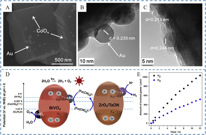
Qi et al. successfully constructed the efficient Z(S)-scheme water splitting system by designing and controlling the load of the Au cocatalyst to the {010} surface of BiVO4 and the CoOx cocatalyst selectively to the {110} surface of BiVO4 by in situ photo-deposition strategy [35]. Representative FESEM and HRTEM images of Au/CoOx-BiVO4 in Figs. 12A-C indicated that Au and CoOx were selectively loaded onto the BiVO4. Fig. 12D is the mechanism of description of ZOWS reaction system. Owning to the advantages of single-electron transfer, suitable neutral environment and low redox potential, [Fe(CN)6]3‒ and [Fe(CN)6]4‒ were taken to act as redox pairs. The Z(S)-scheme heterostructure for photocatalytic overall water splitting is composed with the oxygen producing section of BiVO4 photocatalyst and the hydrogen producing section of ZrO2/TaON photocatalyst. The transfer of electrons from BiVO4 to [Fe(CN)6]3− was facilitated by Au cocatalyst. Also, the selective deposition of the double cocatalyst (Au/CoOx) on the BiVO4 {010} and {110} surfaces could further promote charge separation and enhance oxygen production. The performance of the optimized Z(S)-scheme system for water splitting was exhibited in Fig. 12E. The rates of hydrogen and oxygen production could achieve 130 µmol/h and 65 µmol/h respectively. The selective deposition of the double cocatalyst could facilitate charges separation and transfer to improve the photocatalytic performance of Z(S)-scheme systems. The strategy of improving the efficiency of photocatalysis by cocatalysts loading also provides more ideas for polishing up the performance of Z(S)-scheme water splitting systems in the future.

|
Download:
|
| Fig. 12. (A) Representative FESEM image of Au/CoOx-BiVO4 sample, (B, C) HRTEM images of Au/CoOx-BiVO4 sample. (D) Schematic Description of ZOWS Reaction. (E) Time course of ZOWS on the optimized conditions under visible-light irradiation. Reaction conditions: 50 mg OEP (0.8 wt% Au; 0.1 wt% CoOx), 50 mg HEP (1.0 wt% Rh, 1.5 wt% Cr), 100 mL 25 mmol/L sodium phosphate buffer solution (pH 6.0) containing K4[Fe(CN)6] (10 mmol/L), 300 W xenon lamp (l R 420 nm), temperature 288 K, Pyrex top-irradiation type. Reprinted with permission [35]. Copyright 2018, Elsevier. | |
To sum up, there are various strategies to promote the performances of Z(S)-scheme photocatalytic water splitting systems. The hydrogen evolution rate, STH and durability which are the significant standards to evaluate the performances of Z(S)-scheme photocatalytic systems are listed in Table 1.
|
|
Table 1 The performances of different Z(S)-scheme photocatalytic systems. |

In the process of researching the mechanism of Z(S)-scheme systems, the experimental performance is often not consistent with the theory. Theoretical calculations such as band structure and ultrafast charge dynamics simulation are important aspects of analyzing the working principle of Z(S)-scheme systems. Hybrid density functional theory and excited state ultrafast dynamics simulation are the common measurement methods to explore the mechanism of Z(S)-scheme system [112-114]. Researchers are accustomed to judge the pathway of Z(S)-scheme systems by relying on the direction of the interfacial electric field. The method of judging makes a huge difference between experiments and theories. Hence theoretical calculation is a significant tool to clearly explore the mechanism of Z(S)-scheme photocatalytic systems. As shown in the Fig. 13A, the hybrid density functional theory is combined with the excited state ultrafast dynamic simulation, and a series of typical heterojunctions of X2Y3 ferroelectrics (X: Al, Ga, In) are systematically explored, and it is found that the formation factors of the Z(S)-scheme path come from two aspects. Due to the interfacial electric field, the photogenerated electrons and holes with weak redox ability are significantly enhanced at the interface. On the other hand, for photogenerated electrons/holes with strong redox ability, the weak interfacial non-radiative coupling channel causes the photogenerated electrons/holes to retain high reactivity, so the lifetime of photogenerated electrons/holes can be increased from femtoseconds to hundreds of nanoseconds in the Fig. 13B. The reason that contributing the discrepancy between experimental and theoretical researches is the interface transfer of photogenerated electrons and holes with strong redox ability will not be effectively suppressed by the interfacial electric field. This study helps to deepen the formation mechanism of Z(S)-scheme structured photocatalysts, and provides guidance and assistance for the design of Z(S)-scheme photocatalysts. The hybrid density functional theory used in the Z(S)-scheme system redress the previous misconceptions on the mechanism of Z(S)-scheme system.

|
Download:
|
| Fig. 13. (A) Schematic diagram of the direct Z-scheme heterostructure system. (B) The intralayer and interlayer recombination of photogenerated carriers for BCN. (C) The example of the application of finite element simulation. Reprinted with permission [58]. Copyright 2022, American Chemical Society. Reprinted with permission [112]. Copyright 2013, Springer Nature Limited. | |
As shown in the Fig. 13C, finite element simulation has a wide range of applications in the material structures. In addition to the calculation of the structural properties of the material itself, light absorption can also be simulated by finite element simulation. Obviously, theoretical calculation is an indispensable tool to build an industrialized large-scale Z(S)-scheme photocatalytic system in the future. Theoretical calculation can not only complete the numerical analysis related to Z(S)-scheme systems, but also improve the stability and energy conversion efficiency of Z(S)-scheme systems.
4. ScalableHow to achieve a breakthrough in the Z(S)-scheme system from theory to practice is a significant challenging. Although the conversion of solar energy to hydrogen energy can be achieved by building a Z(S)-scheme semiconductor photocatalyst photolysis system, however it is extremely difficult to build a practical Z(S)-scheme photocatalytic system that can be used for large-scale industrial production [115-121]. Here the optimization of Z(S)-scheme structural system by using gold-based hybridization provides great possibilities for large-scale industrial production. The process of preparing a photocatalyst by using the particle transfer method was illustrated in Fig. 14A. Making SrTiO3 particles doped with La and Rh[(La/(LaCSr) = Rh/(RhCTi) = 4 mol%), SrTiO3: La, Rh] to act as the HEP photocatalyst and BiVO4 particles doped with Mo(Mo/V = 0.05 mol%, BiVO4: Mo) to act as the OEP photocatalyst, then embed them in the Au base (SrTiO3: La, Rh/Au/BiVO4: Mo). Meanwhile the co-catalyst Ru was modified on the surface of SrTiO3: La, Rh particles and BiVO4: Mo particles by photolytic deposition. Then the working mechanism of Z(S)-scheme photocatalytic system was depicted in Fig. 14B. Light excitation electrons are produced in the conduction band of the SrTiO3: La, Rh and BiVO4: Mo when the SrTiO3: La, Rh/Au/BiVO4: Mo been illuminated by visible light, whereas positive holes are generated in the donor levels formed by Rh3+ ions of SrTiO3: La, Rh and in the valence band of BiVO4: Mo. Electron transfer occurs from the conduction band of BiVO4: Mo to the donor levels of SrTiO3: La, Rh via Au. Meanwhile, the excited electrons in SrTiO3: La, Rh reduce water to hydrogen on Ru species which serve as a hydrogen evolution co-catalyst, and holes in BiVO4 oxidize water to oxygen with the aid of RuOx species functioning as an oxygen evolution co-catalyst, achieving overall water splitting. Therefore, the overall water splitting capacity of the photocatalyst tablet should be improved by facilitating the transfer of charge through the underlying gold layer. Fig. 14C is the printed photocatalyst sheet which uses the technology of the screen printing. Here the transforming the Z(S)-scheme photocatalytic system into the printed photocatalyst sheet means the optimized Z(S)-scheme system can be industrialized. To verify the photocatalytic efficiency of the system, Fig. 14D shows the results of the system's hydrogen production and oxygen production over time. Due to the presence of a large amount of gold and the difficulty of depositing the co-catalyst in thick particle layers, the solar-hydrogen conversion efficiency of the printed semiconductor panel is only 0.1%, however the system is still more efficient than similar particle photocatalytic systems reported in the past. The biggest innovation in this article is the realization of the "printing" of the Z(S)-scheme system. The STH of the present SrTiO3: La, Rh/Au/BiVO4: Mo system is limited by the short absorption edge wavelengths of SrTiO3: La, Rh and BiVO4: Mo (520 and 540 nm, respectively). At the same time, the use of Au as a conductor material has also hindered the large-scale production of the system due to the high price, but it provides unlimited possibilities for large-scale production in the future.

|
Download:
|
| Fig. 14. (A) Illustration of the preparation of the SrTiO3: La, Rh/Au/BiVO4: Mo sheet by the particle transfer method. (B) Schematic of overall water splitting on the Ru-modified SrTiO3: La, Rh/Au/BiVO4: Mo sheet. CB, conduction band; VB, valence band. (C) Photograph of the ink used for screen printing the photocatalyst sheet and Photograph of a 10 × 10 cm SrTiO3: La, Rh/Au nanoparticle/BiVO4: Mo printed sheet. (D) Time course of the water splitting reaction using a Ru-modified SrTiO3: La, Rh/Au colloid (40 wt%)/BiVO4: Mo printed sheet under simulated sunlight at 288 K and 5 kPa. The sample (6.25 cm2) was photodeposited with RuCl3·3H2O (0.17 µmol). Reprinted with permission [91]. Copyright 2016, Springer Nature Limited. | |
Previously Kazunari Domen et al. photocatalyzed water splitting through a panel reactor using photocatalyst sheets. Figs. 15A-C show the 100 m2 photocatalyst panel reactor for water splitting. The photocatalytic decomposition system is photocatalyzed by water splitting solar energy to produce hydrogen in a panel reactor using photocatalyst sheets. In the future, the Z(S)-scheme system can be combined into such a photocatalytic water splitting system to achieve the degree of large-scale industrial application, which will solve a large number of energy crisis problems. The further development of lower bandgap energy and cheaper conductor materials will effectively promote the development and industrialization of this photocatalytic system, writing an important part of the grand plan for large-scale industrial production that truly converts solar energy into clean energy.

|
Download:
|
| Fig. 15. (A) A photographic image of a panel reactor unit (625 cm2). (B) The structure of the panel reactor unit viewed from the side. (C) An overhead view of the 100-m2 solar hydrogen production system consisting of 1600 panel reactor units and a hut housing a gas separation facility (indicated by the yellow box). Reprinted with permission [115]. Copyright 2021, Springer Nature Limited. | |
Various strategies have been developed to improve the photocatalytic water splitting performance of Z(S)-scheme systems. These strategies mainly focus on enhancing or extending the range of light absorption, promoting charge separation, and enhancing surface redox reaction. The efficiency of solar energy conversion to hydrogen energy has increased from the extremely low efficiency of the 1970s to about 9% today. When the energy conversion efficiency reaches 5%, the technology can be piloted, and when reaches 10%, it can be applied industrially. The breakthrough in this efficiency is a "dark horse" that is difficult to predict in the field of scientific research, and it is estimated that the efficiency of solar energy conversion is expected to increase to 10% in the near future.
At present, the large-scale research of solar hydrogen production devices is still in the embryonic stage, and there are many key problems, such as low efficiency, small output, high cost and short life, which are difficult to meet the increasing energy demand in the future. The common powder catalyst system has some problems, such as uncontrollable, easy to agglomerate, easy to fall off. On the other hand, electro-assisted photocatalytic systems generally rely on external bias, which leads to complex systems and high operating costs. Both powder and electrocatalysis systems are difficult to meet the requirements of integration, scale and sustainable industrialization. Therefore, it is particularly necessary to develop new principles and methods of heterogeneous integration of materials and devices, so as to solve the integration problem of hydrogen production devices and bring a breakthrough for the scale development of hydrogen production technology by solar energy conversion. Despite these achievements, there are still some challenges needed to be solved and the focus of future studies on catalyst design has been relatively clear as follows: (1) The path of photocatalytic reaction and the separation and recombination mechanism of photogenerated charge should be explored; (2) New electronic mediators should be designed and prepared to promote the separation and transmission of photogenerated charges and increase the number of photogenerated charges involved in photocatalytic reactions; (3) A new type of photocatalytic material system should be developed to meet the kinetic and thermodynamic requirements of photocatalytic reaction, and promote the rapid progress of redox reaction. The problems of reverse reaction, light shielding and side reaction in liquid Z-scheme heterostructure should be solved in near future; (4) The combination of experimental research and theoretical simulation is expected to promote the design and application of Z(S)-scheme heterostructure photocatalyst. This review is beneficial to understand the challenges and opportunities faced by the research field of Z(S)-scheme photocatalytic reaction system, and has important guiding significance for the development and utilization of high-performance Z(S)-scheme photocatalytic reaction system in the future.
Declaration of competing interestWe declare that we have no financial and personal relationships with other people or organizations that can inappropriately influence our work, there is no professional or other personal interest of any nature or kind in any product, service and/or company that could be construed as influencing the position presented in, or the review of, the manuscript entitled.
AcknowledgmentsThis work was financially supported by the Natural Science Foundation of China (Nos. 22202065, 51902101), the Youth Natural Science Foundation of Hunan Province (No. 2021JJ40044), Natural Science Foundation of Jiangsu Province (No. BK20201381), Science Foundation of Nanjing University of Posts and Telecommunications (Nos. NY219144, NY221046), and the Postgraduate Research & Practice Innovation Program of Jiangsu Province (No. SJCX23_0262).
| [1] |
R. Li, H. Chen, J. Xiong, et al., Materials (Basel) 13 (2020) 5057. DOI:10.3390/ma13225057 |
| [2] |
X. Li, C. Garlisi, Q. Guan, et al., Mater. Today 47 (2021) 75-107. DOI:10.1016/j.mattod.2021.02.017 |
| [3] |
H. Li, W. Tu, Y. Zhou, et al., Adv. Sci. 3 (2016) 1500389. DOI:10.1002/advs.201500389 |
| [4] |
B.J. Ng, L.K. Putri, X.Y. Kong, et al., Adv. Sci. 7 (2020) 1903171. DOI:10.1002/advs.201903171 |
| [5] |
X. Hao, Z. Cui, J. Zhou, et al., Nano Energy 52 (2018) 105-116. DOI:10.1016/j.nanoen.2018.07.043 |
| [6] |
L. Wang, C. Bie, J. Yu, et al., Trend. Chem. 4 (2022) 973-983. DOI:10.1016/j.trechm.2022.08.008 |
| [7] |
Q. Xu, L. Zhang, J. Yu, et al., Mater. Today 21 (2018) 1042-1063. DOI:10.1016/j.mattod.2018.04.008 |
| [8] |
R. Zhang, L. Zhang, Q. Zheng, et al., J. Phys. Chem. Lett. 9 (2018) 5419-5424. DOI:10.1021/acs.jpclett.8b02369 |
| [9] |
G. Liao, C. Li, X. Li, et al., Cell Rep. Phys. Sci. 2 (2021) 100355. DOI:10.1016/j.xcrp.2021.100355 |
| [10] |
E.M. Akinoglu, D.A. Hoogeveen, C. Cao, et al., ACS Nano 15 (2021) 7860-7878. DOI:10.1021/acsnano.0c10387 |
| [11] |
X. Niu, X. Bai, Z. Zhou, et al., ACS Catal. 10 (2020) 1976-1983. DOI:10.1021/acscatal.9b04753 |
| [12] |
J. Low, C. Jiang, B. Cheng, et al., Small Methods 1 (2017) 1700080. DOI:10.1002/smtd.201700080 |
| [13] |
P. Raizada, T.H.C. Nguyen, S. Patial, et al., Fuel 303 (2021) 121302. DOI:10.1016/j.fuel.2021.121302 |
| [14] |
C. Bie, L. Wang, J. Yu, Chem 8 (2022) 1567-1574. DOI:10.1016/j.chempr.2022.04.013 |
| [15] |
V. Hasija, V. Nguyen, A. Kumar, et al., J. Haz. Mat. 413 (2021) 125324. DOI:10.1016/j.jhazmat.2021.125324 |
| [16] |
A. Khan, P. Raizada, P. Singh, et al., J. Taiwan. Inst. Chem. E 144 (2023) 104722. DOI:10.1016/j.jtice.2023.104722 |
| [17] |
A. Khan, P. Singh, P. Raizada, et al., Chemosphere 316 (2023) 137839. DOI:10.1016/j.chemosphere.2023.137839 |
| [18] |
V. Dutta, S. Sharma, P. Raizada, et al., J. Environ. Chem. Eng. 8 (2020) 104505. DOI:10.1016/j.jece.2020.104505 |
| [19] |
Y. Kumar, R. Kumar, P. Raizada, et al., J. Mater. Sci. Technol. 87 (2021) 234-257. DOI:10.1016/j.jmst.2021.01.051 |
| [20] |
A. Khan, P. Singh, P. Raizada, et al., J. Ind. Eng. Chem. 98 (2021) 148-160. DOI:10.1016/j.jiec.2021.04.007 |
| [21] |
Q. Xu, L. Zhang, B. Cheng, et al., Chem 6 (2020) 1543-1559. DOI:10.1016/j.chempr.2020.06.010 |
| [22] |
L. Wang, B. Zhu, J. Zhang, et al., Matter 5 (2022) 4187-4211. DOI:10.1016/j.matt.2022.09.009 |
| [23] |
J. Bian, Z. Zhang, J. Feng, et al., Angew. Chem. Int. Ed. 60 (2021) 20906–20914 10633. DOI:10.1002/anie.202106929 |
| [24] |
H. Che, G. Che, H. Dong, et al., Appl. Surf. Sci. 455 (2018) 705-716. DOI:10.1016/j.apsusc.2018.06.038 |
| [25] |
B. Qiu, Q. Zhu, M. Du, et al., Angew. Chem. Int. Ed. 56 (2017) 2684-2688. DOI:10.1002/anie.201612551 |
| [26] |
R. Xue, C. Huang, J. Deng, et al., J. Mater. Chem. A 10 (2022) 3771-3781. DOI:10.1039/d1ta09151d |
| [27] |
S. Nishioka, K. Hojo, L. Xiao, et al., Sci. Adv. 8 (2022) eadc9115. DOI:10.1126/sciadv.adc9115 |
| [28] |
S. Ye, W. Shi, Y. Liu, et al., J. Am. Chem. Soc. 143 (2021) 12499-12508. DOI:10.1021/jacs.1c00802 |
| [29] |
D. Zhao, Y. Wang, C.L. Dong, et al., Nat. Energy 6 (2021) 388-397. DOI:10.1038/s41560-021-00795-9 |
| [30] |
X. Wang, X. Wang, J. Huang, et al., Nat. Commun. 12 (2021) 1-11. DOI:10.1038/s41467-020-20314-w |
| [31] |
Q. Yuan, D. Liu, N. Zhang, et al., Angew. Chem. 129 (2017) 4270-4274. DOI:10.1002/ange.201700150 |
| [32] |
S. Chen, J.J.M. Vequizo, Z. Pan, et al., J. Am. Chem. Soc. 143 (2021) 10633-10641. DOI:10.1021/jacs.1c03555 |
| [33] |
Z. Li, L. Zhang, Y. Liu, et al., Angew. Chem. Int. Ed. 132 (2020) 945-952. DOI:10.1002/ange.201912844 |
| [34] |
J. Wang, L. Xu, T. Wang, et al., Adv. Eng. Mater. 11 (2021) 2003575. DOI:10.1002/aenm.202003575 |
| [35] |
Y. Qi, Y. Zhao, Y. Gao, et al., Joule 2 (2018) 2393-2402. DOI:10.1016/j.joule.2018.07.029 |
| [36] |
C. Sun, L. Wang, W. Zhao, et al., Adv. Funct. Mater. 32 (2022) 2206163. DOI:10.1002/adfm.202206163 |
| [37] |
L. Xie, L. Wang, W. Zhao, et al., Nat. Commun. 12 (2021) 5070. DOI:10.1038/s41467-021-25381-1 |
| [38] |
W. Yin, Y. Cai, L. Xie, et al., Nano Res. (2022). DOI:10.1007/s12274-022-5133-5 |
| [39] |
M. Tang, W. Yin, S. Liu, et al., Crystals 12 (2022) 1218. DOI:10.3390/cryst12091218 |
| [40] |
W. Dong, T. Cai, L. Wang, et al., J. Environ. Chem. Eng. 10 (2022) 108624. DOI:10.1016/j.jece.2022.108624 |
| [41] |
Y. Li, B. Yu, H. Li, et al., Chin. Chem. Lett. 34 (2023) 107874. DOI:10.1016/j.cclet.2022.107874 |
| [42] |
C. Sun, M. Liu, L. Wang, et al., Chin. Chem. Lett. 33 (2022) 1779-1797. DOI:10.1016/j.cclet.2021.08.052 |
| [43] |
J. Wang, H. Chen, L. Tang, et al., Sci. Total. Environ. 639 (2018) 1462-1470. DOI:10.1016/j.scitotenv.2018.05.258 |
| [44] |
L. Wang, L. Xie, W. Zhao, et al., Chem. Eng. J. 405 (2021) 127028. DOI:10.1016/j.cej.2020.127028 |
| [45] |
H. Che, G. Che, E. Jiang, et al., J. Taiwan. Inst. Chem. E 91 (2018) 224-234. DOI:10.1016/j.jtice.2018.05.004 |
| [46] |
H. Che, C. Liu, W. Hu, et al., Catal. Sci. Technol. 8 (2018) 622-631. DOI:10.1039/C7CY01709J |
| [47] |
S. Chen, Y. Qi, T. Hisatomi, et al., Angew. Chem. Int. Ed. 54 (2015) 8498-8501. DOI:10.1002/anie.201502686 |
| [48] |
X. Chen, J. Wang, Y. Chai, et al., Adv. Mater. 33 (2021) 2007479. DOI:10.1002/adma.202007479 |
| [49] |
C. Cheng, B. He, J. Fan, et al., Adv. Mater. 33 (2021) 2100317. DOI:10.1002/adma.202100317 |
| [50] |
H. Deng, X. Fei, Y. Yang, et al., Chem. Eng. J. 409 (2021) 127377. DOI:10.1016/j.cej.2020.127377 |
| [51] |
T. Di, Q. Xu, W. Ho, et al., Chem. Cat. Chem. 1 (2019) 1394-1411. DOI:10.1002/cctc.201802024 |
| [52] |
T. Di, B. Zhu, B. Cheng, et al., J. Catal. 352 (2017) 532-541. DOI:10.1016/j.jcat.2017.06.006 |
| [53] |
C. Chang, L. Wang, L. Xie, et al., Nano Res. 15 (2022) 8613-8635. DOI:10.1007/s12274-022-4507-z |
| [54] |
J. Chen, Y. Tang, S. Wang, et al., Chin. Chem. Lett. 33 (2022) 1468-1474. DOI:10.1016/j.cclet.2021.08.103 |
| [55] |
X. Cheng, L. Wang, L. Xie, et al., Chem. Eng. J. 439 (2022) 135757. DOI:10.1016/j.cej.2022.135757 |
| [56] |
W. Dong, T. Cai, Y. Liu, et al., J. Colloid Interface Sci. 585 (2021) 400-407. DOI:10.1016/j.jcis.2020.11.106 |
| [57] |
J. Li, Y. Zhuang, J. Chen, et al., Energy Chem. 3 (2021) 100060. DOI:10.1016/j.enchem.2021.100060 |
| [58] |
M. Li, L. Wang, X. Zhang, et al., Chin. Chem. Lett. 34 (2023) 107775. DOI:10.1016/j.cclet.2022.107775 |
| [59] |
T. Cai, Y. Liu, L. Wang, et al., J. Colloid Interface Sci. 533 (2019) 95-105. DOI:10.1016/j.jcis.2018.08.074 |
| [60] |
T. Cai, Y. Liu, L. Wang, et al., Appl. Catal. B: Environ. 208 (2017) 1-13. DOI:10.1016/j.apcatb.2017.02.065 |
| [61] |
T. Cai, W. Zeng, Y. Liu, et al., Appl. Catal. B: Environ. 263 (2020) 118327. DOI:10.1016/j.apcatb.2019.118327 |
| [62] |
F. Chen, Q. Yang, F. Yao, et al., J. Catal. 352 (2017) 160-170. DOI:10.1016/j.jcat.2017.04.032 |
| [63] |
Y. Deng, L. Tang, G. Zeng, et al., J. Colloid Interface Sci. 509 (2018) 219-234. DOI:10.1016/j.jcis.2017.09.016 |
| [64] |
S. Chatterjee, P. Bhanja, D. Ghosh, et al., ChemSusChem 14 (2021) 408-416. DOI:10.1002/cssc.202002136 |
| [65] |
S. Tripathy, S. Subudhi, A. Ray, et al., Langmuir 38 (2022) 1766-1780. DOI:10.1021/acs.langmuir.1c02873 |
| [66] |
A. Shi, D. Sun, X. Zhang, et al., ACS Catal. 12 (2022) 9570-9578. DOI:10.1021/acscatal.2c01959 |
| [67] |
Z. Yang, L. Shao, L. Wang, et al., Int. J. Hydrogen. Energ. 45 (2020) 14334-14346. DOI:10.1016/j.ijhydene.2020.03.139 |
| [68] |
W. Zeng, T. Cai, T. Liu, et al., Chem. Eng. J. 381 (2020) 122691. DOI:10.1016/j.cej.2019.122691 |
| [69] |
H. Dong, S. Hong, P. Zhang, et al., Chem. Eng. J. 395 (2020) 125150. DOI:10.1016/j.cej.2020.125150 |
| [70] |
H. Ge, F. Xu, B. Cheng, et al., Chem. Cat. Chem. 11 (2019) 6301-6309. DOI:10.1002/cctc.201901486 |
| [71] |
F. He, B. Zhu, B. Cheng, et al., Appl. Catal. B: Environ. 272 (2020) 119006. DOI:10.1016/j.apcatb.2020.119006 |
| [72] |
Y. Hong, Y. Jiang, C. Li, et al., Appl. Catal. B: Environ. 180 (2016) 663-673. DOI:10.1016/j.apcatb.2015.06.057 |
| [73] |
Z. Jiang, B. Cheng, Y. Zhang, et al., J. Mater. Sci. Technol. 124 (2022) 193-201. DOI:10.1016/j.jmst.2022.01.029 |
| [74] |
J. Jin, J. Yu, D. Guo, et al., Small 11 (2015) 5262-5271. DOI:10.1002/smll.201500926 |
| [75] |
B. Li, C. Lai, P. Xu, et al., J. Clean. Prod. 225 (2019) 898-912. DOI:10.1016/j.jclepro.2019.04.012 |
| [76] |
B. Li, R. Li, H. Zou, et al., Mater. Horiz. 7 (2020) 455-469. DOI:10.1039/c9mh01300h |
| [77] |
C. Li, S. Yu, H. Dong, et al., Appl. Catal. B: Environ. 238 (2018) 284-293. DOI:10.1016/j.apcatb.2018.07.049 |
| [78] |
S. Li, M. Cai, C. Wang, et al., Adv. Fiber Mater. (2023). DOI:10.1007/s42765-022-00253-5 |
| [79] |
Y. Li, Q. Wu, Y. Chen, et al., Appl. Catal. B: Environ. 290 (2021) 120058. DOI:10.1016/j.apcatb.2021.120058 |
| [80] |
S. Li, C. Wang, Y. Liu, et al., Chem. Eng. J. 455 (2023) 140943. DOI:10.1016/j.cej.2022.140943 |
| [81] |
G. Liao, C. Li, S. Liu, et al., Phys. Rep. 983 (2022) 1-41. DOI:10.1016/j.physrep.2022.07.003 |
| [82] |
J. Liu, B. Cheng, J. Yu, et al., Phys. Chem. Chem. Phys. 18 (2016) 31175-31183. DOI:10.1039/C6CP06147H |
| [83] |
Y. Liu, X. Zeng, C. Easton, et al., Nanoscale 12 (2020) 8775-8784. DOI:10.1039/d0nr01611j |
| [84] |
J. Low, B. Dai, T. Tong, et al., Adv. Mater. 31 (2019) 1802981. DOI:10.1002/adma.201802981 |
| [85] |
C. Wang, R. Yan, M. Cai, et al., Appl. Surf. Sci. 610 (2023) 155346. DOI:10.1016/j.apsusc.2022.155346 |
| [86] |
J. Low, J. Yu, C. Jiang, et al., Interface Sci. & Tech. 31 (2020) 193-229. |
| [87] |
A. Meng, B. Cheng, H. Tan, et al., Appl. Catal. B: Environ. 289 (2021) 120039. DOI:10.1016/j.apcatb.2021.120039 |
| [88] |
N. Nie, L. Zhang, J. Fu, et al., Appl. Surf. Sci. 441 (2018) 12-22. DOI:10.1016/j.apsusc.2018.01.193 |
| [89] |
K. Qi, B. Cheng, J. Yu, et al., Chin. J. Catal. 38 (2017) 1936-1955. DOI:10.1016/S1872-2067(17)62962-0 |
| [90] |
Y. Qi, S. Chen, M. Li, et al., Chem. Sci. 8 (2017) 437-443. DOI:10.1039/C6SC02750D |
| [91] |
Q. Wang, T. Hisatomi, Q. Jia, et al., Nat. Mater. 15 (2016) 611-615. DOI:10.1038/nmat4589 |
| [92] |
S. Wang, B. Zhu, M. Liu, et al., Appl. Catal. B: Environ. 243 (2019) 19-26. DOI:10.1016/j.apcatb.2018.10.019 |
| [93] |
X. Wang, S. Li, Y. Ma, et al., J. Phys. Chem. C 115 (2011) 14648-14655. DOI:10.1021/jp2037476 |
| [94] |
Y. Wang, X. Shang, J. Shen, et al., Nat. Commun. 11 (2020) 1-11. DOI:10.1038/s41467-019-13993-7 |
| [95] |
Y. Wang, A. Vogel, M. Sachs, et al., Nat. Energy 4 (2019) 746-760. DOI:10.1038/s41560-019-0456-5 |
| [96] |
P. Xia, B. Zhu, B. Cheng, et al., ACS Sustain. Chem. Eng. 6 (2018) 965-973. DOI:10.1021/acssuschemeng.7b03289 |
| [97] |
Q. Xie, W. He, S. Liu, et al., Chin. J. Catal. 41 (2020) 140-153. DOI:10.1016/S1872-2067(19)63481-9 |
| [98] |
S. Xiong, H. Zeng, Y. Deng, et al., Chem. Eng. J. 451 (2023) 138399. DOI:10.1016/j.cej.2022.138399 |
| [99] |
D. Xu, B. Cheng, W. Wang, et al., Appl. Catal. B: Environ. 231 (2018) 368-380. DOI:10.1016/j.apcatb.2018.03.036 |
| [100] |
F. Xu, K. Meng, S. Cao, et al., ACS Catal. 12 (2021) 164-172. |
| [101] |
M. Cai, Y. Liu, C. Wang, et al., Sep. Purif. Technol. 304 (2023) 122401. DOI:10.1016/j.seppur.2022.122401 |
| [102] |
Y. Li, B. Yu, B. Liu, et al., Chem. Eng. J. 452 (2023) 139542. DOI:10.1016/j.cej.2022.139542 |
| [103] |
M. Liu, H. Li, S. Liu, et al., Nano Res. 15 (2022) 5946-5952. DOI:10.1007/s12274-022-4267-9 |
| [104] |
M. Liu, L.Z. Qiao, B.B. Dong, et al., Appl. Catal. B: Environ. 273 (2020) 119066. DOI:10.1016/j.apcatb.2020.119066 |
| [105] |
X. Liu, Y. Hou, M. Tang, et al., Chin. Chem. Lett. 34 (2023) 107489. DOI:10.1016/j.cclet.2022.05.003 |
| [106] |
S. Wang, L. Wang, L. Xie, et al., Nano Res. 15 (2022) 4996-5003. DOI:10.1007/s12274-022-4158-0 |
| [107] |
W. Zhao, B. Jin, L. Wang, et al., Chin. Chem. Lett. 33 (2022) 557-561. DOI:10.1016/j.cclet.2021.07.035 |
| [108] |
F. Xu, K. Meng, B. Cheng, et al., Nat. Commun. 11 (2020) 1-9. DOI:10.1117/1.jrs.14.024518 |
| [109] |
F. Xu, W. Xiao, B. Cheng, et al., Int. J. Hydrogen. Energ. 39 (2014) 15394-15402. DOI:10.1016/j.ijhydene.2014.07.166 |
| [110] |
F. Xu, L. Zhang, B. Cheng, et al., ACS Sustain. Chem. Eng. 6 (2018) 12291-12298. DOI:10.1021/acssuschemeng.8b02710 |
| [111] |
H. Xu, X. She, T. Fei, et al., ACS Nano 13 (2019) 11294-11302. DOI:10.1021/acsnano.9b04443 |
| [112] |
M. Decker, I. Staude, I. Shishkin, et al., Nat. Commun. 4 (2013) 1-6. DOI:10.30820/9783837966367-1 |
| [113] |
L. Zhang, J. Zhang, H. Yu, et al., Adv. Mater. 34 (2022) 2107668. DOI:10.1002/adma.202107668 |
| [114] |
W. Zhang, A. Mohamed, W. Ong, Angew. Chem. Int. Ed. 59 (2020) 22894-22915. DOI:10.1002/anie.201914925 |
| [115] |
H. Nishiyama, T. Yamada, M. Nakabayashi, et al., Nature 598 (2021) 304-307. DOI:10.1038/s41586-021-03907-3 |
| [116] |
P. Zhou, J. Yu, M. Jaroniec, Adv. Mater. 26 (2014) 4920-4935. DOI:10.1002/adma.201400288 |
| [117] |
B. Zhu, P. Xia, Y. Li, et al., Appl. Surf. Sci. 391 (2017) 175-183. DOI:10.1016/j.apsusc.2016.07.104 |
| [118] |
P. Wang, J. Wang, X. Wang, et al., Curr. Nanosci. 11 (2015) 462-469. DOI:10.2174/1573413711666150130195210 |
| [119] |
J. Low, J. Yu, C. Jiang, et al., J. Colloid Interface Sci. 585 (2021) 820-820. DOI:10.1016/j.jcis.2020.12.038 |
| [120] |
X. Ruan, C. Huang, H. Cheng, et al., Adv. Mater. 35 (2022) 2209141. |
| [121] |
H. Zhu, C. Zhen, X. Chen, et al., Sci. Bull. 67 (2022) 2420-2427. DOI:10.1016/j.scib.2022.11.018 |