 2022, Vol. 33


b MIIT Key Laboratory of Critical Materials Technology for New Energy Conversion and Storage, School of Chemistry and Chemical Engineering, Harbin Institute of Technology, Harbin 150001, China
Using clean solar energy to directly transform CO2 into value-added fuels and chemicals through artificial photosynthesis, known as photocatalytic CO2 reduction reaction [1], is one of the most promising strategies to settle the global ever-growing energy crisis and environmental problems [2]. To promote the economic efficiency of this technology, a vast variety of semiconductor photocatalysts [3-8] have been explored during the last decade. In this regard, increasing the light-harvesting capacity and improving the separation efficiency of photogenerated carriers are two essential motivations for most of the studies [9], which play critical roles in the final photocatalytic performance. In this context, low-cost metal halide perovskite (MHP) nanocrystals (NCs) have been considered as fascinating candidates for photocatalytic CO2 reduction recently [10-14], on primary account of their strong visible light response and superior carrier transport. The photocatalytic CO2 reduction activity of MHP NCs has been greatly improved through surface modification [15-18], morphology control [19-22] and heterojunction engineering [23-34] strategies in the past few years.
Unfortunately, when the photocatalytic reaction is carried out in a water-contained system, the stability of MHP NCs is poor owing to their highly ionic nature [35], especially in the absence of the protection of long alkyl chain ligands, which seriously limits their photocatalytic performance for a long time. Moreover, the long alkyl chain ligand capping on the surface of the perovskites will hinder the separation of surface photogenerated carriers as confirmed in our previously reported work [36, 37]. Therefore, the development of ligand-free MHP NCs is beneficial for improving the photocatalytic activity by increasing the probability of contact between the reaction substrate and the surface of MHP NCs. Nevertheless, the problem of how to improve the stability of MHP NCs without long alkyl chain ligands has not been well solved. In order to conquer this dilemma, herein we prepared a novel ligand-free formamidinium lead bromide (FAPbBr3) based composite by in-situ forming PbI2 on the surface of FAPbBr3 NCs (FAPbBr3/PbI2) via the strategy of ZnI2 isopropanol (IPA) solution assistance. Owing to the high moisture resistivity of PbI2, the resultant FAPbBr3/PbI2 composite exhibits significantly improved stability and activity in comparison with pristine FAPbBr3 NCs for photocatalytic CO2 reduction.
The ligand-free FAPbBr3 NCs were prepared via one-step spin coating process on the filter paper substrate (Fig. S1 in Supporting information). The powder X-ray diffraction (XRD) pattern of as-prepared FAPbBr3 (Fig. S2 in Supporting information) verifies the successful synthesis of cubic phase FAPbBr3 with high purity, displaying distinct characteristic diffraction peaks corresponding to cubic phase FAPbBr3 (Pm3m, No. 221). In addition, high-resolution transmission electron microscopy (HRTEM) image of FAPbBr3 NCs (Fig. S3a in Supporting information) displays the well-defined interplanar distance of 0.42 nm and 0.59 nm, corresponding to the (011) and (001) crystal planes of cubic phase FAPbBr3 [38], respectively, further confirming the successful generation of cubic phase FAPbBr3. Moreover, a sequence of ordered bright spots can be clearly observed in the corresponding fast Fourier transform (FFT) pattern of FAPbBr3 (Fig. S3b in Supporting information), proving once again the well-crystallinity of FAPbBr3 NCs. The composite of ligand-free FAPbBr3/PbI2 was prepared by in-situ constructing PbI2 on the surface of FAPbBr3 NCs via the strategy of ZnI2 IPA solution assisted method as illustrated in Fig. S1, and the details are provided in Supporting information. Briefly, the dried filter paper coated with FAPbBr3 was immersed in ZnI2 IPA solution and annealed at 80 ℃ for 10 min to remove the residual IPA. It is well known that IPA can be used as a weak extractant to extract formamidinium halide from formamidinium lead halide perovskite [39, 40], and its extraction ability can be enhanced by introducing ZnI2 through the reaction of ZnI2 with halide ions to form ZnX3- and ZnX42- [41], where the X denotes the halide ions. Meanwhile, the residual PbI2 could crystallize and retain on the surface of FAPbBr3 owing to its insolubility in IPA. The mass ratio of PbI2 in composite can be determined based on X-ray photoelectron spectroscopy (XPS) analysis, being 2.6%.
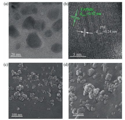
To further explore the structure of the FAPbBr3/PbI2 composite, we first carried out the XRD measurement to analyze the composition of the as-prepared composite. Compared to pristine FAPbBr3 NCs, the main diffraction peaks of cubic phase FAPbBr3 were well maintained on the XRD pattern of FAPbBr3/PbI2 (Fig. S2), while no XRD characteristic peaks of PbI2 can be observed in FAPbBr3/PbI2, which may be due to the low content and small size of PbI2 on the surface of FAPbBr3. While the transmission electron microscopy (TEM) (Fig. 1a) and HRTEM (Fig. 1b) images of FAPbBr3/PbI2 composite display the lattice spacings of 0.42 nm and 0.24 nm for (011) lattice plane of FAPbBr3 and (109) lattice plane of PbI2 (JCPDS-PbI2: 01–073–9472), respectively, implying the existence of PbI2 on the surface of FAPbBr3. High-resolution scanning electron microscopy (HRSEM) measurements revealed that the as-prepared FAPbBr3 sample is irregular nanoparticle with the average size of ~ 20 nm (Fig. 1c), and there are obvious agglomerations due to the lack of surface ligands. ZnI2 IPA solution treatment leads to further increase in reunion (Fig. 1d).

|
Download:
|
| Fig. 1. (a) TEM and (b) HRTEM images of FAPbBr3/PbI2. HRSEM images of (c) FAPbBr3 and (d) FAPbBr3/PbI2. | |
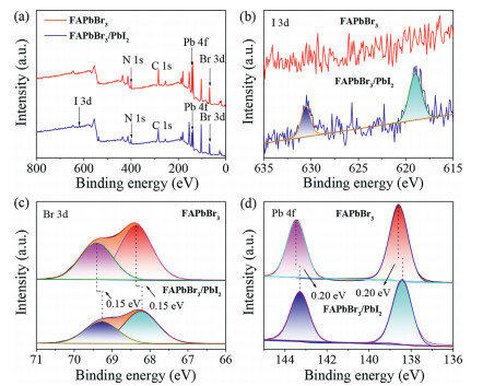
The influence of ZnI2 IPA solution treatment on the interfacial electron structure of halide perovskite was further investigated by recording the XPS spectra of FAPbBr3 NCs and FAPbBr3/PbI2 composite. As shown in Fig. 2a, C, N, Pb and Br co-exist in both as-prepared FAPbBr3 NCs and FAPbBr3/PbI2 composite. Two new peaks at 630.60 and 619.10 eV corresponding to I 3d3/2 and I 3d5/2 can be clearly observed in the FAPbBr3/PbI2 composite as presented in Fig. 2b, which could be attributed to the formation of PbI2 on the surface of FAPbBr3 NCs. It is noted that the characteristic peaks of Br 3d for Br 3d5/2 and Br 3d3/2 in FAPbBr3/PbI2 composite are located 68.25 and 69.25 eV, respectively, which are perceivably lower than those of Br 3d (68.40 and 69.40 eV) in pristine FAPbBr3 NCs as shown in Fig. 2c, indicating the presence of effective electron coupling between FAPbBr3 and PbI2 owing to the close contact between them. This inference can be further confirmed by scrutinizing the changes of Pb 4f signals in FAPbBr3 NCs and FAPbBr3/PbI2 composite (Fig. 2d), which displays the same trend as Br 3d. Moreover, the Fourier transform infrared (FTIR) spectra of as-prepared samples were further measured to scrutinize the interaction between FAPbBr3 and PbI2. With respect to pristine FAPbBr3, there is a new peak occurring near 3550 cm-1 for FAPbBr3/PbI2 (Fig. S4 in Supporting information), which can vest in the Pb-Ⅰ stretching vibration mode [42], indicating the formation of PbI2 on FAPbBr3 nanocrystals. In addition, compared with pristine PbI2, a perceptible shift is occurred for the Pb-Ⅰ vibration of FAPbBr3/PbI2, suggesting a strong interaction between FAPbBr3 and PbI2. This effective electron coupling should be beneficial to the interfacial electron transfer between FAPbBr3 and PbI2.

|
Download:
|
| Fig. 2. XPS spectra for FAPbBr3 and FAPbBr3/PbI2: (a) full spectra, (b) I 3d, (c) Br 3d and (d) Pb 4f. | |
In order to inspect the possible electron transfer orientation between the interface of FAPbBr3/PbI2 composite, we first performed the ultraviolet-visible diffuse reflectance spectroscopy (UV–vis DRS) and electrochemical measurements to obtain the thermodynamic information of components. As presented in Fig. S5 (Supporting information), the absorption spectrum of FAPbBr3/PbI2 shows a perceivable red-shift compared with pristine FAPbBr3, indicating the existence of strong interaction between FAPbBr3 and PbI2 [43], which is consistent with the results of XPS measurements. The corresponding Tauc plots of FAPbBr3 and FAPbBr3/PbI2 are presented in Fig. S6 (Supporting information), where the band gaps (Eg) of FAPbBr3 NCs and FAPbBr3/PbI2 composite can be determined to be 2.25 and 2.22 eV, respectively. The values of conduction band edge potentials (ECB) can be derived from the Mott-Schottky curves (Fig. S7 in Supporting information), being −1.10 and −0.98 V vs. the normal hydrogen electrode (NHE) for FAPbBr3 and FAPbBr3/PbI2, respectively. In combination with the values of Eg, the values of valance band edge potentials (EVB) for FAPbBr3 and FAPbBr3/PbI2 can be obtained as 1.15 and 1.24 V vs. NHE, respectively. In addition, according to the previously reported values [41], the values of ECB and EVB for PbI2 are −1.00 and 1.17 V vs. NHE, respectively. Therefore, a type-Ⅱ band alignment could be formed between the interface of FAPbBr3 and PbI2, as illuminated in Fig. S8 (Supporting information), indicating that the photogenerated electron transfer from FAPbBr3 to PbI2 is thermodynamically feasible. In addition, ultraviolet photoelectron spectra (UPS) of FAPbBr3 and FAPbBr3/PbI2 were further measured to obtain the information of Fermi levels (EF), which also play an important role in the interfacial free electron transfer process. As depicted in Fig. S9 (Supporting information), the calculated value of EF for FAPbBr3 (−4.14 eV vs. vacuum) is lower than that of FAPbBr3/PbI2 composite (−3.93 eV vs. vacuum), indicating that the EF of PbI2 on the FAPbBr3 surface is higher than that of FAPbBr3. When FAPbBr3 and PbI2 are in contact, the free electrons in PbI2 will transfer into FAPbBr3 to realize the EF equilibrium of composite. This is in line with the XPS results in Fig. 2, in which the binding energies of Pb 4f and Br 3d in composite shift towards lower values compared to FAPbBr3, which can be attributed to Pb and Br in composite exposing to a more negative chemical environment. A built-in electric field pointing from PbI2 to FAPbBr3 will be constructed by free electron movement at the interface between FAPbBr3 and PbI2, which also facilitates the photogenerated electron transfer from FAPbBr3 to PbI2.
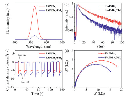
The detailed charge transfer dynamics between FAPbBr3 and PbI2 were further evaluated by monitoring the steady state photoluminescence (PL) and time-resolved PL (TRPL) decay curves of FAPbBr3 NCs and FAPbBr3/PbI2 composite. As depicted in Fig. 3a, pristine FAPbBr3 NCs displayed a strong emission peak at 525 nm, while the PL emission intensity was sharply quenched to 12% after in-situ conversion of PbI2 on the surface of FAPbBr3. This observation was in accordance with the photographs of FAPbBr3 NCs and FAPbBr3/PbI2 composite under UV illumination (Fig. S10 in Supporting information), revealing the occurrence of swift charge transfer between FAPbBr3 and PbI2. Fig. 3b displays the TRPL decay curves of FAPbBr3 NCs and FAPbBr3/PbI2 composite, where an obviously accelerated PL decay for FAPbBr3/PbI2 can be identified compared with pristine FAPbBr3 NCs. The corresponding fitting parameters based on a triple-exponential function were summarized in Table S1 (Supporting information). The PL average lifetimes for FAPbBr3 NCs and FAPbBr3/PbI2 composite are calculated as 39.2 and 18.0 ns, respectively, further demonstrating the swift charge transfer between FAPbBr3 and PbI2. In addition, the photocurrent response (I-t) and electrochemical impedance spectroscopy (EIS) measurements further confirmed that in-situ formation of PbI2 on the surface of FAPbBr3 is beneficial to the charge separation. FAPbBr3/PbI2 composite exhibits larger photocurrent intensity (Fig. 3c) and smaller semicircular radius in Nyquist plots (Fig. 3d) with respect to individual FAPbBr3 NCs.

|
Download:
|
| Fig. 3. (a) Steady state PL spectra, (b) time-resolved PL decay curves, (c) photocurrent response, and (d) photoelectrochemical impedancespectroscopy (EIS) plots of FAPbBr3 and FAPbBr3/PbI2. | |
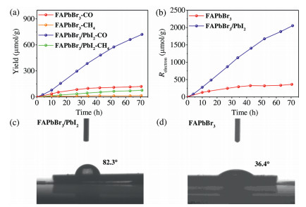
The photocatalytic performance for CO2 reduction was evaluated in a gas-solid system (see details in Supporting information). For FAPbBr3 NCs and FAPbBr3/PbI2 composite, the major products of CO2 reduction are CO and CH4. As presented in Fig. 4a, the in-situ formation of PbI2 on the surface of FAPbBr3 can significantly enhance the photocatalytic activity and stability of FAPbBr3. The yields of CO and CH4 for FAPbBr3/PbI2 composite achieve impressive values of 720 and 76.5 µmol/g, respectively, after 70 h of irradiation. The corresponding electron consumption (Relectron = 2nproduct (CO) + 8nproduct (CH4), nproduct denotes the yield of product) yield is 2053 µmol/g for FAPbBr3/PbI2 composite (Fig. 4b), which is about 7-fold over that of pristine FAPbBr3 NCs. What is more, there is no obvious decrease in CO evolution for FAPbBr3/PbI2 composite after 70 h of illumination, while the pristine FAPbBr3 loses its photocatalytic activity after 20 h, owing to the destroyed structure during photoreaction as identified by the XRD measurements (Fig. S11a in Supporting information). In contrast, FAPbBr3/PbI2 composite can maintain its crystal structure well after photocatalytic reaction (Fig. S11b in Supporting information). Moreover, after the photocatalytic reaction, there is no change in XPS characteristic peaks (Fig. S12 in Supporting information) of FAPbBr3/PbI2 composite, further suggesting the good stability of FAPbBr3/PbI2 in this gas-solid reaction, which can be further confirmed by photocatalytic cycling experiment (Fig. S13 in Supporting information). The good stability of FAPbBr3/PbI2 should be attributed to the high moisture resistivity of PbI2, which endows FAPbBr3/PbI2 with a larger water contact angle of 82.3° (Fig. 4c) than that of 36.4° (Fig. 4d) for pristine FAPbBr3 NCs, protecting FAPbBr3 NCs from water corrosion. In addition, a sequence of control experiments was conducted with FAPbBr3/PbI2 as catalyst. As shown in Fig. S14 (Supporting information), without catalyst, CO2 or H2O vapor, there are negligible CO and CH4 can be detected, indicating that the products of CO and CH4 come from the photocatalytic reduction of CO2 over catalyst. According to the test result of 13CO2 labeling experiment (Fig. S15 in Supporting information), the major reaction products 13CO with m/z value of 29 and 13CH4 with m/z value of 17 can be obviously observed, further confirming that the C in CO and CH4 products originate from the reduction of CO2 by photogenerated electrons in FAPbBr3/PbI2. In addition, H218O labeling experiment was also performed (Fig. S16 in Supporting information), and 18O2 with m/z value of 36 can be also obviously observed, indicating that water is the reductant.

|
Download:
|
| Fig. 4. (a) The evolution of CO and CH4 yield and (b) corresponding Relectron with FAPbBr3, FAPbBr3/PbI2 as photocatalysts. Images of water droplets between water and (c) FAPbBr3/PbI2 or (d) FAPbBr3 on the silicon substrate. | |
To summarize, we have demonstrated a facile strategy to improve the water tolerance of ligand-free MHP NCs in a water-contained photocatalytic reaction system, by in-situ forming PbI2 on the surface of ligand-free FAPbBr3 NCs with the assistance of ZnI2 IPA solution. The formation of PbI2 layer not only significantly ameliorates the stability of MHP NCs for photocatalytic CO2 reduction with H2O vapor as electron source, but also brings forth an accelerated interfacial charge separation as demonstrated by the photophysical and electrochemical measurements. The improved stability and charge separation endow the FAPbBr3/PbI2 composite with a remarkable improvement of photocatalytic performance for CO2 reduction, achieving an inspiring electron consumption yield of 2053 µmol/g without any organic sacrificial agents, over 7-fold higher than that of individual FAPbBr3 NCs.
Declaration of competing interestThe authors declare that they have no known competing financial interests or personal relationships that could have appeared to influence the work reported in this paper.
AcknowledgmentThis work was supported by the Natural Science Foundation of Tianjin City (No. 17JCJQJC43800).
Supplementary materialsSupplementary material associated with this article can be found, in the online version, at doi:10.1016/j.cclet.2021.09.033.
| [1] |
T. Inoue, A. Fujishima, S. Konishi, K. Honda, Nature 277 (1979) 637-638. DOI:10.1038/277637a0 |
| [2] |
O.S. Bushuyev, P. De Luna, C.T. Dinh, et al., Joule 2 (2018) 825-832. DOI:10.1016/j.joule.2017.09.003 |
| [3] |
L. Yang, Y. Peng, X. Luo, et al., Chem. Soc. Rev. 50 (2021) 2147-2172. DOI:10.1039/D0CS00445F |
| [4] |
J. Wang, S. Lin, N. Tian, et al., Adv. Funct. Mater. 31 (2021) 2008008. DOI:10.1002/adfm.202008008 |
| [5] |
X.B. Li, Z.K. Xin, S.G. Xia, et al., Chem. Soc. Rev. 49 (2020) 9028-9056. DOI:10.1039/D0CS00930J |
| [6] |
W. He, X. Wu, Y. Li, et al., Chin. Chem. Lett. 31 (2020) 2774-2778. DOI:10.1016/j.cclet.2020.07.019 |
| [7] |
Y. Yang, M. Wu, X. Zhu, et al., Chin. Chem. Lett. 30 (2019) 2065-2088. DOI:10.1016/j.cclet.2019.11.001 |
| [8] |
R. Li, W. Zhang, K. Zhou, Adv. Mater. 30 (2018) 1705512. DOI:10.1002/adma.201705512 |
| [9] |
W. Zhang, A.R. Mohamed, W.J. Ong, Angew. Chem. Int. Ed. 59 (2020) 22894-22915. DOI:10.1002/anie.201914925 |
| [10] |
S. Bera, N. Pradhan, ACS Energy Lett. 5 (2020) 2858-2872. DOI:10.1021/acsenergylett.0c01449 |
| [11] |
C. Yuan, Y. He, R. Chen, et al., Sol. RRL 5 (2021) 2000419. DOI:10.1002/solr.202000419 |
| [12] |
J. Chen, C. Dong, H. Idriss, O.F. Mohammed, O.M. Bakr, Adv. Energy Mater. 10 (2020) 1902433. DOI:10.1002/aenm.201902433 |
| [13] |
H. Huang, B. Pradhan, J. Hofkens, M.B.J. Roeffaers, J.A. Steele, ACS Energy Lett. 5 (2020) 1107-1123. DOI:10.1021/acsenergylett.0c00058 |
| [14] |
C. Han, X. Zhu, J.S. Martin, et al., ChemSusChem 13 (2020) 4005-4025. DOI:10.1002/cssc.202000953 |
| [15] |
Y.W. Liu, S.H. Guo, S.Q. You, et al., Nanotechnology 31 (2020) 215605. DOI:10.1088/1361-6528/ab72be |
| [16] |
Z. Chen, Y. Hu, J. Wang, et al., Chem. Mater. 32 (2020) 1517-1525. DOI:10.1021/acs.chemmater.9b04582 |
| [17] |
S. Shyamal, S.K. Dutta, N. Pradhan, J. Phys. Chem. Lett. 10 (2019) 7965-7969. DOI:10.1021/acs.jpclett.9b03176 |
| [18] |
Y.F. Mu, W. Zhang, X.X. Guo, et al., ChemSusChem 12 (2019) 4769-4774. DOI:10.1002/cssc.201902192 |
| [19] |
L.Y. Wu, M.R. Zhang, Y.X. Feng, et al., Sol. RRL 5 (2021) 2100263. DOI:10.1002/solr.202100263 |
| [20] |
S. Shyamal, S.K. Dutta, T. Das, et al., J. Phys. Chem. Lett. 11 (2020) 3608-3614. DOI:10.1021/acs.jpclett.0c01088 |
| [21] |
S.H. Guo, J. Zhou, X. Zhao, et al., J. Catal. 369 (2019) 201-208. DOI:10.1016/j.jcat.2018.11.004 |
| [22] |
J. Hou, S. Cao, Y. Wu, et al., Chem. Eur. J. 23 (2017) 9481-9485. DOI:10.1002/chem.201702237 |
| [23] |
M. Que, Y. Zhao, Y. Yang, et al., ACS Appl. Mater. Interfaces 13 (2021) 6180-6187. DOI:10.1021/acsami.0c18391 |
| [24] |
L. Li, Z. Zhang, C. Ding, J. Xu, Chem. Eng. J. 419 (2021) 129543. DOI:10.1016/j.cej.2021.129543 |
| [25] |
J.Y. Li, H.Y. Chen, Y. Jiang, D.B. Kuang, Sol. RRL 5 (2021) 2100036. |
| [26] |
F. Xu, K. Meng, B. Cheng, et al., Nat. Commun. 11 (2020) 4613. DOI:10.1038/s41467-020-18350-7 |
| [27] |
H. Huang, J. Zhao, Y. Du, et al., ACS Nano 14 (2020) 16689-16697. DOI:10.1021/acsnano.0c03146 |
| [28] |
Y. Jiang, H.Y. Chen, J.Y. Li, et al., Adv. Funct. Mater. 30 (2020) 2004293. DOI:10.1002/adfm.202004293 |
| [29] |
J. Wang, J. Wang, N. Li, et al., ACS Appl. Mater. Interfaces 12 (2020) 31477-31485. DOI:10.1021/acsami.0c08152 |
| [30] |
Y.F. Mu, W. Zhang, G.X. Dong, et al., Small 16 (2020) 2002140. DOI:10.1002/smll.202002140 |
| [31] |
Y. Jiang, J.F. Liao, H.Y. Chen, et al., Chem 6 (2020) 766-780. DOI:10.1016/j.chempr.2020.01.005 |
| [32] |
X. Wang, J. He, J. Li, et al., Appl. Catal. B 277 (2020) 119230. DOI:10.1016/j.apcatb.2020.119230 |
| [33] |
M. Ou, W. Tu, S. Yin, et al., Angew. Chem. Int. Ed. 57 (2018) 13570-13574. DOI:10.1002/anie.201808930 |
| [34] |
Y.F. Xu, M.Z. Yang, B.X. Chen, et al., J. Am. Chem. Soc. 139 (2017) 5660-5663. DOI:10.1021/jacs.7b00489 |
| [35] |
H. Huang, M.I. Bodnarchuk, S.V. Kershaw, M.V. Kovalenko, A.L. Rogach, ACS Energy Lett. 2 (2017) 2071-2083. DOI:10.1021/acsenergylett.7b00547 |
| [36] |
Y. Xu, W. Zhang, K. Su, et al., Chem. Eur. J. 27 (2021) 2305-2309. DOI:10.1002/chem.202004682 |
| [37] |
Y.F. Mu, C. Zhang, M.R. Zhang, et al., ACS Appl. Mater. Interfaces 13 (2021) 22314-22322. DOI:10.1021/acsami.1c01718 |
| [38] |
D. Han, M. Imran, M. Zhang, et al., ACS Nano 12 (2018) 8808-8816. DOI:10.1021/acsnano.8b05172 |
| [39] |
T. Li, M. Ren, Y. Zhang, et al., Small 16 (2020) 2001866. DOI:10.1002/smll.202001866 |
| [40] |
J.J. Yoo, S. Wieghold, M.C. Sponseller, et al., Energy Environ. Sci. 12 (2019) 2192-2199. DOI:10.1039/C9EE00751B |
| [41] |
D.P. Graddon, C.S. Khoo, Polyhedron 7 (1988) 2129-2133. DOI:10.1016/S0277-5387(00)81791-X |
| [42] |
K. Kaviyarasu, D. Sajan, M.S. Selvakumar, S.A. Thomas, D.P. Anand, J. Phys. Chem. Solids 73 (2012) 1396-1400. DOI:10.1016/j.jpcs.2012.06.005 |
| [43] |
M. Ou, S. Wan, Q. Zhong, et al., Appl. Catal. B 221 (2018) 97-107. DOI:10.1016/j.apcatb.2017.09.005 |