 2018, Vol. 29


Lithium ion batteries (LIBs) is widely used in portable electronic products, electric vehicles, secondary energy storage and other fields due to its large energy density, high power density and long lifespan [1-3]. Nowadays, requirements for high performance of LIBs are put forward with the development of science and technology in order to meet people's needs. Development of advanced anode materials is one of the keys for LIBs with high storage capacities and outstanding stabilities [4]. Silicon [5-7], tin [8-10], titanium [11] and other materials have high theoretical specific capacities, but they usually suffer from large volume expansions during charge and discharge process, which could lead to the pulverization after multiple cycles, then resulting in a decrease of cycling performance [12-14]. Carbon materials are widely used in LIBs as anode materials due to their low cost, abundant resources, and structural stability. A classical graphite anode has a limited theoretical capacity of 372 mAh/g. Thus, tremendous efforts have been devoted to develop advanced anode materials with improved energy and power densities to meet the ever-increasing high energy demands for various technological applications.
To improve the electrochemical performance of carbon materials, many types carbonaceous materials were manufactured, including carbon nanosphere [15, 16], carbon nanotubes [17, 18] and graphene oxide [19], etc. The nanoscale carbon materials can increase the contact areas between electrode and electrolyte with shortening the distances of lithium ion diffusion. Meanwhile, the transition metal combined with carbon materials was also an effective strategy to enhance the electrochemical performance on account of high theoretical specific capacity [20-25]. Many researches had proved that the unique structure design and synergistic effect not only settle the challenges of low conductivity and poor cycling stability of transition metal but also resolve the imperfection of inferior specific capacity of traditional graphite materials [2, 26-31]. Another approach to increase the electrochemical performance for carbon anode is to modify its surface functional groups with heteroatoms such as B, S, P and N [19, 32-35]. Especially, nitrogen was known as a highly efficient doping agent to enhance the electrochemical performance. Theoretical study has shown that N-doped resulted in the higher positive charge on a carbon atom adjacent to the nitrogen atoms, and a positive shift of Fermi energy at the apex of the Brillouin zone of grapheme [36]. It is reported that the doping of pyrrolic-N and pyridinic-N can not only change the electronic state of the carbon surface and improve the conductivity of the material, but also can bring in defects to increase the carbon material surface and lithium ion binding sites, thereby enhancing the performance of lithium storage [37]. At present, many studies obtained N-doped carbon materials by using ammonia [4], melamine [38] and urea [39]. Our previous work proved that the use of N-containing aromatic ring precursors with high temperature treatment can achieve the effect of adjusting the N atom doping form, which could be used as free-standing electrodes for high-performance supercapacitors [40].
Carbon nanofiber is an interesting candidate among carbonaceous anode materials due to its 1D nanostructure, good electronic conductivity and free-standing characteristics [41]. With robust body and sufficient conductivity, carbon nanofiber could be made into free-standing electrodes without use of any binders or conductive additives. It is well known that carbon nanofibers can be obtained from polyacrylonitrile (PAN), mesophase pitch, or rayon. Nowadays, PAN serves as the precursors for over 90% of all nanofibers. However, the PAN, like other precursors, requires a series of complicated process of oxidative stabilization prior to final carbonization, in which the linear structures are transformed to ladder-shaped ones with infusibility. The oxidation stabilization step is slow and difficult to control. Therefore, some other materials such as polyimide (PI) and poly-p-phenylenebenzobisoxazole (PBO) were developed to be candidates for carbon precursors, which yield high-quality carbon materials without complex stabilization process.
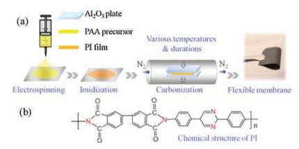
Compared with other precursors, PI possesses aromatic heterocyclic rings with semi-ladder structure, resulting in a high carbon yield and superior thermal stability. And a wide range of selections in the molecular unit supply a variety structures for PI precursors. Hence, in this work, we choose heterocyclic PI structures with biphenyl and pyrimidine rings to fabricate nanofiber membranes by electrospinning technology. Carbon nanofiber membranes were obtained by subsequent thermal treatment for a prolonged time. In general, PI nanofiber membranes are usually fabricated by a widely developed and practical two-step technique, in which polyamic acid (PAA) precursor nanofiber membranes are firstly obtained by electrospinning and then converted to yellow PI membranes through thermal or chemical imidization process (Fig. 1a). Herein, heterocyclic PI nanofiber membranes containing biphenyl and pyrimidine rings (Fig. 1b) were firstly fabricated. And they translated into black carbon membranes with free-standing and flexible features through the heat treatment, which could be directly used as anode electrodes for lithium ion batteries without additives and current collectors. The influences of factors such as pyrolysis temperature and durations of heat treatment on the microstructures and electrochemical properties were also investigated in this work.

|
Download:
|
| Fig. 1. (a) Schematic of the fabrication process of PI-derived carbon nanofiber membranes including electrospinning, imidization and carbonization. (b) The chemical structure of PI with biphenyl and pyrimidine rings. | |
Scanning electron microscopy (SEM) images demonstrate that both of the electrospun PAA and PI nanofibers after imidization exhibit a good homogeneity with smooth surface without "beads" (Fig. S1 in Supporting information), indicating that the formation of imide ring does not change the surface morphologies of the nanofibers. But the diameters of nanofibers lightly decrease from an average value of 248 nm for PAA to 242 nm for PI nanofibers. The chemical structure conversion from PAA to PI could be confirmed by Fourier transform infrared (FTIR) spectroscopy (Fig. S1). The appearance of new absorption peaks at 732 cm-1 (C=O bending mode of imide ring), 1362 cm-1 (C-N stretching mode), 1703 cm-1 (C=O symmetric stretching mode of imide groups), and 1777 cm-1 (C=O asymmetric stretching mode of imide groups) confirms the successful and complete imidization process to convert to PI nanofibers [42]. The disappearance of absorption band at 3257 cm-1 (-OH stretching vibration) for PI nanofibers indicates the removal of -OH, further proving the formation of the cyclic imide rings. Besides, the signal at 1427 cm-1 could be attributed to the stretching vibrations of the pyrimidine rings inherited from diamine units.
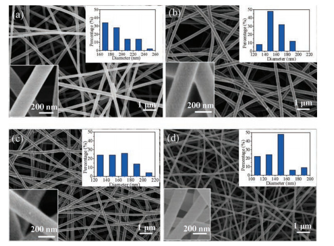
After being subjected at high temperatures, the yellow PI membrane converted into black carbon nanofiber membranes. SEM image of obtained PI-650 (Fig. 2a) shows an average diameter of about 193 nm for the nanofibers, and these values rapidly decline to 181 nm, 155 nm and 137 nm for PI-750, PI-850 and PI- 950, respectively (Figs. 2b-d), which is consistent with the structure change for PI-derived carbon fibers carbonized at high temperatures [43, 44]. Thermal gravimetric analysis (TGA) curve (Fig. S2 in Supporting information) displays a significant weight loss onset of 600-650 ℃ and FTIR spectra demonstrate that obvious structural changes with the disappearance of the characteristic signals for PI structure between PI-550 and PI- 650, indicating that the transformation of the polymer structure into polycarbon-chain formation occurs at about 650 ℃. The products treated with different durations at high temperatures also show the decreased trend of diameters with the extended durations (Fig. S3 in Supporting information). Enlarged SEM images of the cross section for PI-650 (Fig. S4 in Supporting information) exhibit the random nanofibers with continuous network structures and uniform distribution of C with residue N elements over the whole nanofibers. It illustrates that although the polymer structure changes consistently with the carbonization temperatures and durations, the integrity of the nanofiber membranes are well maintained with outstanding mechanical strength, which can be bent to arbitrary shapes without deteriorating its integrity (Fig. 1a), making it a perfect electrode for flexible LIBs.

|
Download:
|
| Fig. 2. EM images of fresh PI-derived carbon nanofiber membranes with histograms of fibrous dimeter and enlarged images. (a) PI-650, (b) PI-750, (c) PI-850 and (d) PI-950. | |
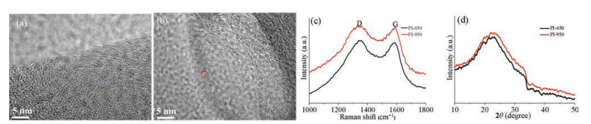
Transmission electron microscopy (TEM) studies reveal that PI- 650 shows an amorphous structure without obvious graphene layers, a reflection of insufficient energy for carbonization due to the low processing temperature (Fig. 3a). In contrast, PI-950 exhibits a short-range order with the interlayer spacing of about 0.34 nm, which was close to the graphite interlayer (002) spacing [45] (Fig. 3b). It demonstrates that more of the graphitic structures are developed when the carbonization process is conducted at a higher temperature. Raman spectra were further applied to study the structural changes of PI nanofiber membranes. Two typical Raman peaks at around 1343 cm-1 and 1582 cm-1 are attributed to the D band and G band (Fig. 3c), which could be assigned to the disordered turbostratic structures and graphitic carbon [46], respectively. The intensity ratio of G peak and D peak (IG/ID) could be applied as a parameter to determine the graphitization degrees. Here, the ratio IG/ID of PI-650 is 0.968, lower than that of PI-950 of 0.993, indicating a slightly increase of the graphitization degree from 650 ℃ to 950 ℃. The values for PI-650-3h and PI-650-10h are 1.04 and 1.05, respectively, suggesting a higher graphitization degrees with longer durations at high temperature (Fig. S5 in Supporting information). However, the degrees of graphitization for our membranes are relatively lower than those of graphitized materials, as a very high temperature usually up to 1000 ℃ is usually required for graphitization process. The board X-ray diffraction (XRD) patterns (Fig. 3d) around 2θ = 25° also indicates that the fabricated carbon products are mainly composed of amorphous carbon even after the treatment at 950 ℃.

|
Download:
|
| Fig. 3. TEM images of (a) PI-650 and (b) PI-950 and (c) Raman spectra and (d) XRD profiles for PI-650 and PI-950. | |
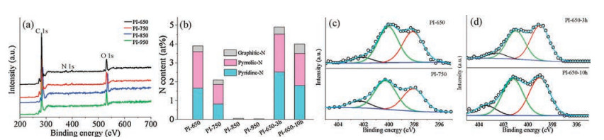
To investigate the surface compositions of carbonization materials, X-ray photoelectron spectrum (XPS) measurements were further carried out. The wide scan of XPS spectra show the existence of N and O elements, indicating that although noncarbon atoms are generally removed at high temperatures, partial heteroatoms are also preserved in the carbonized products (Fig. 4a). The surface analysis of XPS demonstrates that the N content for PI-650, PI-750, PI-650-3h and PI-650-10h are 3.9 at%, 2.1 at%, 4.9 at% and 4 at%, respectively, and the values for PI-850 and PI-950 could be neglected (Fig. 4b). It suggests that high temperatures could help remove the defects, during which the heteroatoms of N are largely eliminated. But prolonged durations at appropriate low temperature (e.g., 650 ℃) might be beneficial to stable the N atoms and give a large residue of N elements during the process of removing other components such as C and O. The N 1s peak in the XPS spectrum shows an intensive band in the binding energy range of 395-405eV, which can be deconvoluted by peaks centered round 398.5 (pyridinic-N), 400.4 (pyrrolic-N) and 401-403eV (graphitic-N) (Figs. 4c and d). From the summarized N content and compositions (Fig. 4b), the proportion of pyridinic and pyrrolic N in PI-650 (3.6 at%) is higher than that of PI- 750 (1.9 at%) and PI-650-3h demonstrates the highest value of 4.5 at% with the pyridinic-N making the largest contribution to the N content. Besides, the resistivity of the membranes consistently decreased with increasing carbonization temperature and prolonged durations, by almost six orders of magnitude when the temperature was increased from 650 ℃ to 950 ℃ and two order of magnitude when the durations was extended from 0.5h to 10h (Fig. S6 in Supporting information). It is well known that a high Ndoping level is beneficial to effectively adsorb Li+ and a high electrical conductivity of carbon nanofiber membranes favors charge transfer when they are employed as anode in LIBs. But the balance between the carbonization level and the N-containing defect sites exhibits more crucial to achieve large reversible Li storage at high charge/discharge rate.

|
Download:
|
| Fig. 4. XPS wide spectra (a) and ratios of different types of N-doping (b) for various samples; deconvoluted N1s spectra for (c) PI-650, PI-750 and (d) PI-650-3h, PI-650-10h. | |
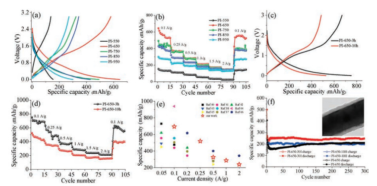
The electrochemical performance of as-prepared carbon nanofiber membranes was evaluated in a half-cell in a 1mol/LLiPF6 in DC/DMC electrolyte as a lithium foil as the counter/reference electrode. The charge-discharge curves at 0.1A/g for samples treated with various temperatures show similar steep chargedischarge curves with no obvious plateaus in the entire voltage range from 0.01V to 3V (Fig. 5a). This charge-discharge behavior is well consistent with the profiles in the previous reports [47]. It shows that PI-550 delivery the lowest capacity among all electrodes, which might be attributed to its inadequate carbonization at very low temperature. The specific capacities of PI-650, PI-750, PI-850 and PI-950 are 645.4mAh/g, 491.4mAh/g, 428.6mAh/g and 300.3mAh/g, respectively, indicating that the electrochemically active N content in PI-650 makes a larger contribution than the carbonization lever to the Li storage. From the profiles of rate performance at various current densities from 0.1A/g to 2A/g (Fig. 5b), PI-650 electrodes deliver average specific capacities of 560mAh/g, 371mAh/g, 282mAh/g, 214mAh/g, 174mAh/g, and 149mAh/g at different current densities when the current densities increase from 0.1A/g to 2A/g and a value of 535mAh/g could be maintained when the current density changes back to 0.1A/g. With the increase of carbonization temperature, although the electrical conductivity of the materials gradually increased, but the N defect sites decreased, making the specific capacities of the products gradually reduced. Cyclic voltammetry (CV) profiles also demonstrate the oxidationpeak around1.0-1.3V, which could be assigned to the reaction of Li ions with the defects induced by N-containing functional groups [48] (Fig. S7 in Supporting information). This peak current decreased with increasing carbonization temperature owing to the gradual reduction in N content as proved by XPS analyses. The peak in the range 0.4-0.6V is associated with the formation of solid electrolyte interphase (SEI) films [49, 50], i.e., the decomposition of the electrolytes on the surface of carbon electrodes, which are the main reason of the initial irreversible capacity (Table S1 in Supporting information). Besides, PI-650 displays a higher Columbic efficiency (CE) of about 47.2% for the first cycle than those of other samples except PI-550, which might be attributed to the stable formation of SEI film and the less residues of oxygencontaining surface functional groups in PI-650. Although PI-550 showing a relatively high CE value of about 55.8%, the inactive groups and poor conductivity with insufficient heat-treatment lead to a very low specific capacity for PI-550. It is noted that the discrepancy in capacity was narrowed when the applied current density increased as the capacity difference discharged at 2A/g was almost negligible among PI-650 and PI-950. It suggests that the PI-950 show better capacity retention at high current densities than that of PI-650, indicating that the electrical conductivity played an important role in determining the rate performance of the electrodes. This could be further evidenced by the electrochemical impedance spectra (Fig. S8 in Supporting information), showing lowered charge transfer resistance of PI-950 than that of PI-650.

|
Download:
|
| Fig. 5. Charge-discharge curves (a), (c) and rate performance (b), (d) for various samples with different calcinations temperatures and durations. (e) Comparison of specific capacity vs. current densities of PI-650-3h with reported results and (f) cycling performance for various products with the inset of SEM image for PI-650-3h after 300 cycling. | |
For the electrodes with different durations during carbonization process, the charge-discharge curves display a higher specific capacity of 750mAh/g for PI-650-3h than those of PI-650 and PI- 650-10h (Fig. 5c). The larger capacity of PI-650-3h is due to the nitrogen containing functional groups that positively affect the reversible Li storage capability because of the stronger electro negativity of nitrogen than carbon, and the hybridization between the nitrogen lone pair electrons and the graphitic carbon π system [16]. The profiles of rate performance exhibit that PI-650-3h shows higher specific capacities at different current density than those of PI-650 with the values of 695 mAh/g, 519 mAh/g, 376 mAh/g, 257 mAh/g, 239 mAh/g, and 213 mAh/g at 0.1 A/g, 0.25 A/g, 0.5 A/g, 1 A/g, 1.5 A/g, 2 A/g, respectively (Fig. 5d). The investigation of rate performances for samples subjected to 550 ℃ and 850 ℃ with duration 3 h (donated as PI-550-3h and PI-850-3h) (Fig. S9 in Supporting information) further prove that PI-650-3h owns the highest overall capacity among all temperature and duration ranges studied. It is reported that the pyridinic and pyrrolic carbon, especially the former one, are suitable for Li storage with a high storage capacity, while the graphitic structure is the weakest of the three types. From the XPS results above, PI-650-3h demonstrates the highest value of 4.5 at% with the pyridinic-N making the largest contribution to the N content, leading to a better electrochemical performance than those of other samples. In addition, it is demonstrated that PI-650-3h anodes show better Li storage properties than those of reported PAN-derived electrospun products or comparable to other carbon materials [9, 45, 46, 51-56] (Fig. 5e), suggesting heterocyclic PI as a favorable precursor for high-capacity carbon-based anode materials for LIBs. Moreover, the electrodes were cycled for 300 cycles at a high current density of 1.5 A/g to evaluate the long-term stability of the freestanding membranes (Fig. 5f) and a value of 245 mAh/g could be maintained. It shows that PI-650-3h still keeps the higher capacity and better cycling stability with nearly no decay, further demonstrating a moderate temperature of 650 ℃ and duration of 3 h favorable for the highest overall capacity among all temperature and time ranges studied. An obvious volumetric expansion of PI-650-3h could be observed by the TEM characterization after cycling, which might be attributed to the release of interlayer stress for the lithium accommodation on the surface without deteriorating their own structures [46].
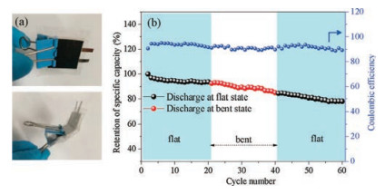
As discussed, with appropriate calcination temperature and duration, favorable flexible anode materials are fabricated from heterocyclic PI nanofiber membranes containing biphenyl and pyrimidine rings. The conductive networks arising from PI-derived carbon nanofiber membranes increase the conductivity of the electrode and the N dopants inherited from PI structures provide more active sites for Li storages. Furthermore, to investigate the potential of as-prepared PI-derived carbon nanofibers for use as flexible electrodes, a flexible cell was assembled and tested to obtain the effect of bending on the electrochemical performance. It is obvious that the capacity of the battery being bent have a negligible decrease compared with that of the original flat unit (Fig. 6). Moreover, the flexible battery showed a good cyclic stability both under flat and bent states. With respect to the original capacity, it showed capacity retention of about 92.5% after the first 20 cycles under a flat state and about 84.4% after another 20 cycles under a bent state. Such a facile and practical fabrication process with heterocyclic PI structures as precursors for carbon nanofiber membranes might be an efficient rout to design and fabricate high performance flexible electrode materials for LIBs.

|
Download:
|
| Fig. 6. (a) Photograph of the battery tested at the flat and bent states. (b) Cyclic performance of the battery under flat and bent states. | |
In conclusion, heteroatoms-doped carbon nanofiber membranes with flexible features were prepared by electrospinning with heterocyclic PI structures containing biphenyl and pyrimidine rings. The treatment temperature and time had strongly affected average diameters and nitrogen content of materials and further affected its electrochemical performance. The resultant product which treated at 650 ℃ for 3 h exhibited the excellent rate and cyclic performance with 695 mAh/g reversible specific capacity at 0.1 A/g and a retain value of 245 mAh/g at 1.5 A/g after 300 cycles with good electrochemical performance under bent state as integrated electrode for flexible device. We believe that such low cost, high-performance anodes fabricated by heterocyclic PI precursors and scalable electrospinning techniques can offer a great promise in grid-scale electrode materials for flexible LIBs.
AcknowledgmentsThis work was financially supported by the DHU Distinguished Young Professor Program and the National Natural Science Foundation of China (No. 51403036).
Appendix A. Supplementary dataSupplementary data associated with this article can be found, in the online version, at https://doi.org/10.1016/j.cclet.2017.12.015.
| [1] |
L. Hao, Z. Zheng, B. Chen, L.X. Wang, Nanoscale Res. Lett. 12 (2017) 302-308. DOI:10.1186/s11671-017-2058-0 |
| [2] |
L. Zhang, D. Ge, G. Qu, et al., Nanoscale 9 (2017) 5451-5545. DOI:10.1039/C7NR01425B |
| [3] |
T.F. Yi, X. Han, B. Chen, Y.R. Zhu, Y. Xie, J. Alloy. Compd. 703 (2017) 103-113. DOI:10.1016/j.jallcom.2017.01.342 |
| [4] |
X. Liu, Y. Wu, Z. Yang, et al., J. Power Sources 293 (2015) 799-805. DOI:10.1016/j.jpowsour.2015.05.074 |
| [5] |
M. Piwko, T. Kuntze, S. Winkler, et al., J. Power Sources 351 (2017) 183-191. DOI:10.1016/j.jpowsour.2017.03.080 |
| [6] |
T. Yoon, T. Bok, C. Kim, et al., ACS Nano 11 (2017) 4808-4815. DOI:10.1021/acsnano.7b01185 |
| [7] |
J.R. Szczech, S. Jin, Energy Environ. Sci. 4 (2010) 56-72. |
| [8] |
W. Dong, J. Xu, C. Wang, et al., Adv. Mater. 29 (2017) 136-145. |
| [9] |
P. Dou, Z. Cao, C. Wang, J. Zheng, X. Xu, Appl. Surf. Sci. 404 (2017) 342-349. DOI:10.1016/j.apsusc.2017.01.253 |
| [10] |
D. Zhou, W.L. Song, X. Li, L.Z. Fan, Y. Deng, J. Alloy. Compd. 699 (2017) 730-737. DOI:10.1016/j.jallcom.2016.12.426 |
| [11] |
H. Choi, H. Park, H.U. Ji, W.S. Yoon, H. Choe, Appl. Surf. Sci. 411 (2017) 363-367. DOI:10.1016/j.apsusc.2017.03.122 |
| [12] |
Z. Wang, L. Zhou, X.W. Lou, Adv. Mater. 24 (2012) 1903-1911. DOI:10.1002/adma.v24.14 |
| [13] |
W. Xu, T. Wang, S. Wu, S. Wang, J. Alloy. Compd. 698 (2016) 68-76. |
| [14] |
Q. Yang, T. Sun, J.Y. Yu, J.X. Ma, Chin. Chem. Lett. 27 (2016) 412-416. DOI:10.1016/j.cclet.2015.12.025 |
| [15] |
L. Wan, J. Wang, L. Xie, Y. Sun, K. Li, ACS Appl. Mater. Interfaces 6 (2014) 15583-15596. DOI:10.1021/am504564q |
| [16] |
Z. Guo, Y. Zhong, Y. Liu, C. Mao, et al., Chin. Chem. Lett. 28 (2017) 743-747. DOI:10.1016/j.cclet.2016.10.007 |
| [17] |
H.G. Wang, C. Yuan, R. Zhou, Q. Duan, Y. Li, J. Chem. Eng. 316 (2017) 1004-1010. DOI:10.1016/j.cej.2017.02.059 |
| [18] |
S. Ahmad, D. Copic, C. George, M. De Volder, Adv. Mater. 28 (2016) 6705-6710. DOI:10.1002/adma.201600914 |
| [19] |
Z.S. Wu, W. Ren, L. Xu, F. Li, H.M. Cheng, ACS Nano 5 (2011) 5463-5471. DOI:10.1021/nn2006249 |
| [20] |
S.W. Park, H.W. Shim, J.C. Kim, et al., J. Alloy Compd. 728 (2017) 490-496. DOI:10.1016/j.jallcom.2017.09.023 |
| [21] |
J.G. Wang, H. Liu, H. Liu, et al., Chem. Eng. J. 328 (2017) 591-598. DOI:10.1016/j.cej.2017.07.039 |
| [22] |
H. Ning, H. Xie, Q. Zhao, et al., J. Alloy. Compd. 722 (2017) 716-720. DOI:10.1016/j.jallcom.2017.06.099 |
| [23] |
Y. Cai, J. Ma, T. Wang, J. Alloy. Compd. 582 (2014) 328-333. DOI:10.1016/j.jallcom.2013.07.206 |
| [24] |
L. Wang, J. Ma, L. Chen, et al., Electrochim. Acta 113 (2013) 194-199. DOI:10.1016/j.electacta.2013.09.094 |
| [25] |
Y. Cai, X. Li, L. Wang, et al., J. Mater. Chem. A 3 (2015) 1396-1399. DOI:10.1039/C4TA04537H |
| [26] |
J. Wu, X. Qin, C. Miao, et al., Carbon 98 (2015) 582-591. |
| [27] |
J. Chen, X. Wu, Y. Gong, et al., Ceram. Int. 43 (2016) 4655-4662. |
| [28] |
L. Li, P. Liu, K. Zhu, et al., Electrochim. Acta 235 (2017) 79-87. DOI:10.1016/j.electacta.2017.03.071 |
| [29] |
W. Wang, Z. Favors, C. Li, et al., Sci. Rep. 7 (2017) 44838-44847. DOI:10.1038/srep44838 |
| [30] |
F. Sun, J. Gao, H. Wu, et al., Carbon 113 (2017) 46-54. DOI:10.1016/j.carbon.2016.11.039 |
| [31] |
Z. Xie, C. Jiang, W. Xu, et al., Electrochim. Acta 235 (2017) 613-622. DOI:10.1016/j.electacta.2017.03.099 |
| [32] |
X. Liu, D. Teng, T. Li, et al., J. Power Sources 272 (2014) 614-621. DOI:10.1016/j.jpowsour.2014.08.084 |
| [33] |
Y.P. Wu, S. Fang, Y. Jiang, R. Holze, J. Power Sources 108 (2002) 245-249. DOI:10.1016/S0378-7753(02)00013-7 |
| [34] |
Y. Yan, Y.X. Yin, S. Xin, Y.G. Guo, L.J. Wan, Chem. Commun. 48 (2012) 10663-10665. DOI:10.1039/c2cc36234a |
| [35] |
W. Kicinski, M. Szala, M. Bystrzejewski, Carbon 68 (2014) 1-32. DOI:10.1016/j.carbon.2013.11.004 |
| [36] |
J. Shen, W. Hu, Y. Li, et al., J. Alloy. Compd. 701 (2017) 372-379. DOI:10.1016/j.jallcom.2017.01.100 |
| [37] |
A.L. Reddy, A. Srivastava, S.R. Gowda, et al., ACS Nano 4 (2010) 6337-6342. DOI:10.1021/nn101926g |
| [38] |
D. Nan, Z.H. Huang, F.Y. Kang, W.C. Shen, Carbon 110 (2016) 521-521. |
| [39] |
G. Wu, R. Li, Z. Li, et al., Electrochim. Acta 171 (2015) 156-164. DOI:10.1016/j.electacta.2015.05.016 |
| [40] |
Y. Li, J. Dong, J. Zhang, et al., Small 11 (2015) 3476-3484. DOI:10.1002/smll.v11.28 |
| [41] |
J.W. Jung, C.L. Lee, S. Yu, et al., J. Mater. Chem. A 4 (2016) 703-750. DOI:10.1039/C5TA06844D |
| [42] |
F. Gan, J. Dong, W. Tan, et al., J. Mater. Sci. (2017) 1-12. |
| [43] |
M. Jing, C.G. Wang, Q. Wang, Y.J. Bai, B. Zhu, Polym. Degrad. Stabil. 92 (2007) 1737-1742. DOI:10.1016/j.polymdegradstab.2007.05.020 |
| [44] |
J. Liu, P.H. Wang, R.Y. Li, J. Appl. Polym. Sci. 52 (2010) 945-950. |
| [45] |
X. Li, N. Fu, J. Zou, et al., Electrochim. Acta 225 (2017) 137-142. DOI:10.1016/j.electacta.2016.12.127 |
| [46] |
X. Zhang, G. Zhu, M. Wang, et al., Carbon 116 (2017) 686-694. DOI:10.1016/j.carbon.2017.02.057 |
| [47] |
Y. Wu, M.V. Reddy, B.V. Chowdari, S. Ramakrishna, ACS Appl. Mater. Interfaces 5 (2013) 12175-12184. DOI:10.1021/am404216j |
| [48] |
B. Zhang, Y. Yu, Z.L. Xu, et al., Adv. Energy Mater. 4 (2014) 1634-1642. |
| [49] |
Z.L. Wang, D. Xu, H.G. Wang, Z. Wu, X.B. Zhang, ACS Nano 7 (2013) 2422-2430. DOI:10.1021/nn3057388 |
| [50] |
Y. Matsumura, S. Wang, J. Mondori, J. Electrochem. Soc. 142 (1995) 2914-2918. DOI:10.1149/1.2048665 |
| [51] |
D. Nan, J.G. Wang, Z.H. Huang, et al., Electrochem. Commun. 34 (2013) 52-55. DOI:10.1016/j.elecom.2013.05.010 |
| [52] |
L. Ji, Y. Yao, O. Toprakci, et al., J. Power Sources 195 (2010) 2050-2056. DOI:10.1016/j.jpowsour.2009.10.021 |
| [53] |
B.S. Lee, S.B. Son, K.M. Park, et al., ACS Appl. Mater. Interfaces 4 (2012) 6702-6710. DOI:10.1021/am301873d |
| [54] |
L. Ji, X. Zhang, Nanotechnology 20 (2009) 155705-155712. DOI:10.1088/0957-4484/20/15/155705 |
| [55] |
B. Zhang, Z.L. Xu, Y.B. He, et al., Nano Energy 4 (2014) 88-96. DOI:10.1016/j.nanoen.2013.12.011 |
| [56] |
Y.R. Ren, B. Yang, H.M. Wei, J.N. Ding, Solid State Ionics 292 (2016) 27-31. DOI:10.1016/j.ssi.2016.05.002 |