 2017, Vol. 28


Over the past decades, dielectric polymers are rapidly emerging as novel materials for diverse engineering applications, such as energy storage and conversion [1-6], electrocaloric cooling [7, 8], actuators [9-11], and sensors [12-14], since they have advantages in high voltage rating and processing ease over conventional ceramic dielectrics. Unfortunately, most of the commercial polymers suffer from limited dielectric constant (2 < k < 5) due to the electronic and atomic polarization of hydrocarbon covalent bonds [5], and thereby fall short of the rising demands for the higher functionality and further miniaturization of next-generation electronic and electrical devices. The key to address this issue is to substantially raise the dielectric constant of polymers, meanwhile retaining their other inherent properties, such as high breakdown strength and low dielectric losses.
The introduction of high-k nanofillers into polymer matrices to form nanocomposite dielectrics represents a straightforward avenue to this end [15-17]. The rationale behind this approach lies in the combination of the impressive dielectric constant of filler particles and the high dielectric strength and low dielectric losses of polymer matrices. In such way, the high-k nanoparticles contribute to the increment of the effective dielectric constant of nanocomposites in terms of the effective medium theory. Previous studies validate that the dielectric properties can be fine tailored by rationally selecting the shape and size of high-k fillers as well as modulating the anisotropy or topological structure of the nanocomposites [18-20]. Indeed, numerous research has succeeded in improving the overall dielectric performances using 0-D metal oxide nanoparticles such as copper calcium titanate (CCTO) [21], 1D perovskite fibers such as TiO2 [22, 23], BaTiO3 [24-27], BaSrTiO3 [28], and 2D nanosheets boron nitride (BN) [29, 30] and montmorillonite (MMT) [31, 32]. The huge interfaces in the nanocomposites play an important role in determining the dielectric constant and losses at low fields via promoting interfacial exchange coupling. Meanwhile, the high-field dielectric behaviors of nanocomposites such as dielectric breakdown strength can be also altered by mitigating the multiplication of free electrons through collisions, in particular as the particles are aligned perpendicular to the applied electric field [19]. Different from the spherical high-k fillers, the introduction of anisotropic nanoparticles with high aspect ratios can induce strong dielectric anisotropy and thereby open additional flexibility in tuning the dielectric properties of polymer matrices [18].
Despite high-k can be achieved in ceramic/polymer nanocomposites, the fundamental drawback of such approach lies in that most of the increase in k is contributed by an increase in the average field in the polymer matrix with very little of the charges being stored in the high-k filler phase because of the inhomogeneous field distribution resulting from the large contrast of dielectric constant between the filler and matrix. Consequently, very high filler loading is necessary, usually over 50 vol%, to realize a high enough dielectric constant (k ~ 100). Such high loading of inorganic powders, however, not only significantly deteriorates the mechanical flexibility of final composites, but also causes porosity which in return dramatically decreases the dielectric properties of the composites. Therefore, there is a real need to develop extremely high-k polymer composites at low filler loadings.
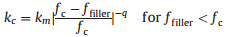
An alternative approach to increase the effective dielectric constant of polymers is to replace ceramic nanoparticles with conductive ones in the polymer composites. By establishing the percolation transition of conducting fillers, one can observe a nonlinear scaling of physical properties of the composites instead of the linear mixture based on the effective medium theory. For instance, a dielectric constant several tens times higher than the virgin polymer could be achieved as the particle loading is in the vicinity of the percolation threshold. In this case, the dielectric constant, kc, of the percolative composites is inversely related to the difference between actual filler loading ffiller and the critical filler loading fc, which can be described by a classic explicit law [15, 33]:
|
(1) |
where km is the dielectric constant of the matrix, fc the percolation threshold, and q dielectric critical exponent. This divergent behavior of dielectric constant can be explained by employing the microcapacitor model based on the near-percolated networks [34-36]. Fig. 1 schematically illustrates the microstructure evolution with increasing particle concentration in a polymer matrix. In the loading range far from fc, the particles are dispersed in the matrix and more or less isolated from each other. The slight increase in dielectric constant is ascribed to the introduction of polarizable domains [37]. In the vicinity of fc and below it, the dielectric constant diverges. In this case, a near-percolated network forms with a large number of conducting clusters being separated by a very thin polymer layer in between. This effect locally creates microcapacitors that contribute to an abnormally large capacitance of the composite, consequently give rise to a jump of the dielectric constant [38]. In the vicinity of fc and above it, the material becomes electronically conductive owing to the direct contact of conducting clusters and loses the capability of storing charges. Therefore, this approach suffers from a weakness that is the substantial increase of losses in the vicinity of percolation. The losses can arise from dielectric losses related to the motion of bound charges of the dielectrics as well as from the intrinsic conductivity owing to the transportation of the free charges of the conducting particles [37, 39]. The high-k and lowloss polymer composites remain challenging but can certainly be approached by developing a fine degree of the structure of nearpercolated network of the nanoparticles within the polymer matrix.

|
Download:
|
| Fig. 1. Microstructure evolution with increasing particle loading in a polymer matrix. Clusters of the particles in a composite near percolation can form microcapacitors that contribute to significant increase in the dielectric constant. Adapted from Ref. [40]. | |
Up to now, exceptionally high k values have been realized in systems made by mixing polymers with various conducting particles including metal particles [41, 42], carbon nanofiber [43], and carbon nanotubes (CNTs) [39, 44, 45], and graphene [35, 46, 47]. Comparing to the metal particles, the carbon nanomaterials are more favorable to serve as conducting filler in high-k percoaltive systems, because they exhibit better mechanical flexibility and lighter weight, particularly open opportunities for the interfacial engineering based on their surface chemistry [48]. However, challenges still exist today in the field on finely controlling the network morphology to achieve high dielectric constant and low losses simultaneously. The relationship between the morphology of near-percolated networks and the dielectric properties of composites is raising a number of fundamental questions. To provide a comprehensive understanding on these questions, we review recent progress toward high-k percolative polymer composites based on carbon nanomaterials. Particular attention is paid on the effect of the morphology of near-percolated networks on the dielectric properties. Some perspectives and topics that warrant further investigation in the near future are also addressed.
2. High-k polymer composites based on randomly dispersed carbon nanoparticlesThe divergent behavior of dielectric constant near percolation is universal in diverse electrically heterogeneous systems composed of conducting nanoparticles in insulating mediums. Randomly mixing is the simplest and easiest way to form near-percolated network in polymer matrices. Until now, most of the reported high-k polymer composites are based on randomly dispersed nanoparticles. The observed high k values range from several tens to thousands [49]. For instance, Chen et al. [50] demonstrated a percolative film with conductive acetylene black introduced into polyvinylidene fluoride (PVDF). The dielectric constant reached 56 and the dielectric loss was below 0.15 when acetylene black concentration was in the neighborhood of fc (~1.3%). Compared to 0-D carbon nanoparticles, 1D carbon materials with large aspect ratios and high specific surface areas are expected to lead to improved dielectric performances. Wang et al. [44] investigated untreated CNTs/PVDF composites and found that the dielectric constant at 1 kHz was as high as 300 for the composite with 2.0 vol % of CNTs, while the dielectric loss was less than 0.4 at the same frequency. Recently, He et al. [46] proposed to employ 2D nanoparticle, graphite nanoplate, to pursure high-k polymer nanocomposites. A large k value of 2700 was observed at 100 Hz near percolation threshold as low as 1 vol%.
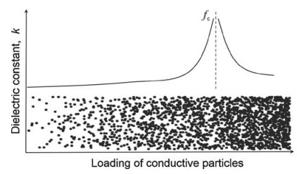
Principally, the maximum k value theoretically can be infinitely high because of its divergent behavior near percolation. But in the real systems, the dielectric constant is always limited and differs from each other. The large deviations of k observed in different systems can be attributed to the intrinsic properties of polymers and nanofillers [51-53], and to the size, shape of the nanoparticles [34, 54, 55], but mainly to the lack of fine control of the morphology of the near-percolated networks due to the random dispersion of fillers. To establish a controllable near-percolated network, the carbon nanoparticles must be uniformly dispersed and ideally strongly interact with surrounding polymer macromolecules. This can be actually achieved by enginnering the interfacial properties of the nanocomposites. For instance, Dang et al. [56] have chemically modified CNT fillers with 3, 4, 5-trifluorobromobenzene (TFBB) and then compounded them with PVDF to create dielectric composites (Fig. 2a). The modification of CNT with TFBB improved the interaction between the functionalized CNTs and surrounding PVDF chains owing to a large number of fluoride groups existing on the surface of treated nanotubes. The dielectric constant can reach 5000 at 100 Hz when the volume fraction of functionalized CNT is 15%. The giant dielectric constant originated from the Maxwell- Wagner-Sillars (MWS) effect as a result of the formation of the near-percolated network. The nomadic charge carriers were blocked at the internal interfaces between the CNT and the PVDF, and the large π-orbital of the CNT provided the nomadic electrons with large domains. Strongly electrophilic F groups on the treated CNTs further reinforced this MWS effect. However, it should be noted that the conductivity of composite is as high as 10-3 S/m at CNT loading of 15 vol% and thus gives rise to very high losses due to the transportation of free charges.

|
Download:
|
| Fig. 2. (a) Schematic illustration of the wet-chemistry procedure for preparing CNT/PVDF composites. (b) PVDF polymer chains wrap over CNTs via the remarkable donoracceptor complexes that are established between the delocalized 'π-electron' clouds of CNTs and strongly electrophilic F groups of PVDF chains. Reprinted with permission [57], Copyright 2011 American Chemical Society (c) Schematic of the fabrication procedure for TiO2 coated graphene hybrid sheets. Reproduced with permission [58]. Copyright 2011, Royal Society of Chemistry. | |
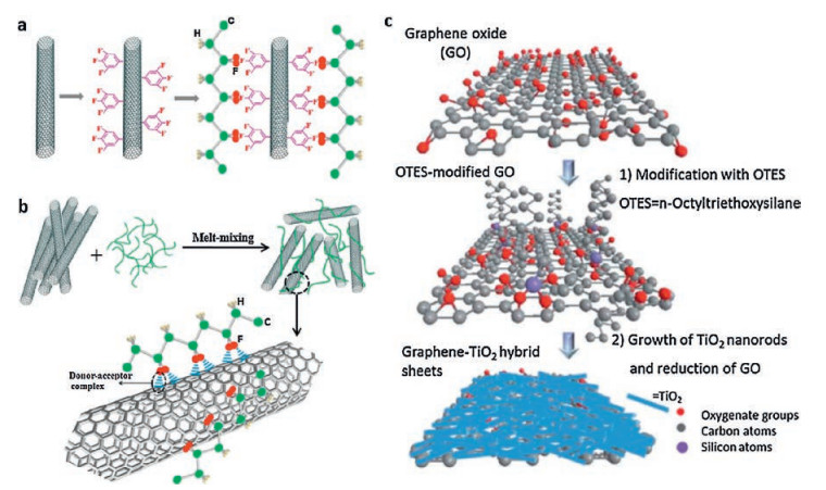
Quantum tunneling between adjacent CNTs is the main limitation for electrical conductance in polymer composites near percolation. Increasing the contact resistivity associated with interfaces via CNT surface engineering can be an efficient way to achieve percolative composites with suppressed dielectric losses. With maintaining the superlative properties of CNTs, non-covalent wrapping of polymer macromolecules onto individual CNT surface is much desirable to fully realize the true potential of CNTs in dielectric CNT/polymer composites. Yuan et al. [57] adopted melt mixing to randomly disperse CNTs within PVDF host polymer. The high temperature and high shear forces are expected to cause chemical and/or physical interactions between nanotubes and macromolecules, such as CH-π interaction and π-π stacking [59]. A remarkable interaction at molecular level is eventually achieved by establishing donor-acceptor complexes between the delocalized 'π-electron' clouds of CNTs and strongly electrophilic F groups of PVDF chains (Fig. 2b). This strong interfacial interaction is confirmed by the shift of G band as well as the formation of thin PVDF layers on the MWNT surface [57]. In detail, as shown in Fig. 3a-b, the diameter of the CNTs in the composite obviously becomes larger than pristine ones. This indicates the effective wrapping of host polymer chains on the CNTs' surfaces. The thickness of the PVDF layer is ranging from 10 nm to 30 nm, which is verified by the TEM characterization of the CNTs before and after melt-blended with PVDF (Fig. 3c, d). The existence of PVDF layer creates an advanced material with individual nanotube dispersion. As approaching a critical concentration (fc ~ 10 vol%), the established near-percolated network allows for the formation of microcapacitors with nanotubes as electrodes and polymer in between as dielectric. Such network morphology has two significant benefits. First it fully takes the advantage of the high specific surface area of nanotubes and results in a huge interfacial area which serves as the site for additional polarizability. Second, the interfacial polarization, within the microcapacitors, can be significantly reinforced because of the formation the donoracceptor complexes. The delocalized 'π-electron' clouds of MWNTs provide large domains for nomadic electrons, and the electrophilic F groups strongly attract these electrons. These unique features of individual CNT network consequently give rise to a dielectric constant of 320 at 100 Hz while retaining the loss tangent below 0.34 (Fig. 3e, f).

|
Download:
|
| Fig. 3. SEM images of (a) pristine CNTs and (b) fractured surface of the PVDF composite loaded with 10 vol% CNTs. TEM images of (c) pristine CNT and (d) CNT with a thin PVDF layer. The frequency dependence of (e) dielectric constant and (f) loss tangent of CNT/PVDF composites, measured at room temperature. Reprinted with permission [58]. Copyright 2011, American Chemical Society. | |
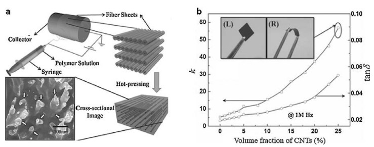
Comparing to the non-covalent wrapping of polymer chains on nanoparticles, directly introducing a solid inter-particle barrier layer can be more efficient to suppress the tunneling current through near-percolated networks and hence lead to a far lower dielectric loss [58, 60-64]. For instance, Nan's group [63] developed an organic polysulfone (PSF) dielectric coating on CNTs by using a simple electrospinning method. The PSF acted not only as a barrier to prevent CNTs from direct connection, but also as a polymer matrix after fusion by hot-pressing (Fig. 4a). The resultant composites showed a dielectric constant of 58 as the nanotube content reached 25 vol%, while there was only a slight change in loss tangent (0.02 → 0.05 at 1 MHz, Fig. 4b).

|
Download:
|
| Fig. 4. (a) Schematic illustration for the preparation of CNT/PSF composites. The inset is the SEM image of cross-section of the composites perpendicular to the fiber direction, CNTs are indicated by arrows. (b) The dielectric constant and loss tangent of the composites as a function of the CNT loading, measured at 1 MHz. The photograph in the inset of (b) shows that the composite can be largely deformed. Reproduced with permission [63]. Copyright 2011, Wiley-VCH. | |
In addition to the polymer inter-particle barrier layer, high-k ceramic nanoparticles have been also proposed to decorate carbon nanomaterials as an inorganic shell. As such, the morphology of near-percolated network can be fine controlled by altering the amount of the particle decoration in order to reach the optimum combination of high k and low losses. Wu et al. [58] reported a 2D sandwich-like graphene-TiO2 hybrid sheet (Fig. 2c), which can serve as ideal core-shell fillers for low-loss percoaltive composites. The decoration of TiO2 nanorods prevents direct contact between the graphene sheets in the composite, allowing for forming numerous microcapacitors and suppressing the tunneling current. Consequently, by randomly dispersing 11 vol% hybrid sheets into a polystyrene matrix, the k of the composite can reach more than 1700 at 100 Hz, yet the loss tangent is only 0.39.
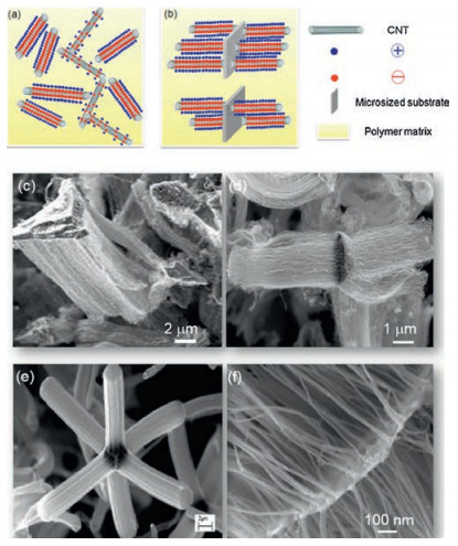
3. High-k polymer composites based on confined dispersion of carbon nanoparticlesIn terms of microcapacitor model, to achieve an extremely high dielectric constant in percolative polymer composites, one has to exponentially decrease the inter-particle distance by concentrating the filler in composites. While this brings a risk, the formation of long-range conducting path, which delocalizes charges on a macroscopic scale (Fig. 5a). To overcome such paradox, the key is to rationally design an optimal near-percolated network, which favors the microcapacitor formation yet prevents the electronic conduction. In addition to the well-studied strategy of introduction of inter-particle barrier layer, Yuan et al. proposed a concept of "local alignment of nanoparticles" to form highly effective microcapacitors, which leads to a favorable combination of high-k and low loss [34, 35, 45, 65]. For instance, the local alignment of CNTs can be realized by confining CNT arrays on a micrometer-sized inorganic substrate in polymer composites. Locally aligned CNTs with polymer in between them form intrinsic natural capacitor structures to store charges, more importantly, avoid the relaxation of charges stored if they are well isolated to each other (Fig. 5b). The key to achieve local alignment of CNTs in composites is to retain the integrity of the CNT arrays during composite fabrication in the means of attaching them onto a rigid microplatelet. Meanwhile, the microplatelet should be capable of serving as substrate for the chemical vapor deposition (CVD) synthesis of CNT arrays.

|
Download:
|
| Fig. 5. Schematic illustration of percolative polymer composites based on (a) randomly distributed CNTs and (b) vertically aligned CNT arrays on microplatelets. In the latter case, the whole hybrids are randomly dispersed yet the CNT arrays are confined locally by being attached on the substrates. SEM images of various CNT based nano-micro hybrid particles: (c) "single direction" CNT-SiC hybrid, (d) "two direction" CNT-SiC hybrid. Images (a-d) are reproduced with permission [34]. Copyright 2014, American Chemical Society. (e) CNT-Al2O3 hybrid, and (f) CNTgraphene nanoplatelet hybrid. | |
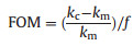
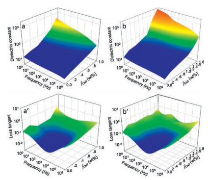
In the past years, vertically aligned CNT arrays have been successfully synthesized on distinct micrometer-sized particles, such as SiC platelets, Al2O3, graphene nanoplatelet, as shown in Fig. 5c-f. Amazingly, the morphology of such hybrids, like length, diameter, and even the growth direction of CNTs, can be controlled by optimizing CVD conditions [66]. For example, by varying CVD conditions, two different CNT-SiC hybrids were realized [55]: (ⅰ) CNTarrays were grown uniformly along a single direction (denoted as "single-direction" hybrid, Fig. 5c). (ⅱ) The growth of CNT arrays was along two opposite directions perpendicular to the flat surfaces of SiC particles (denoted as "two-direction" hybrid, Fig. 5d). After blended with PVDF matrix, the unique architecture of hybrids can be retained. A much more effective microcapacitor network with parallel CNTs as electrode can then be formed near percolation, which has a strong effect on the k improvement. The k increases abruptly near percolation due to the steep rise of the number of microcapacitors as a result of interactions between hybrids. As shown in Fig. 6. The maximum dielectric constant observed is 473 and 1627 at 1 Hz in 'single-direction' and 'twodirection' composite respectively and their corresponding loss tangent is 0.70 and 0.43. More importantly, these improvements were achieved at a very low filler loading, showing a much higher figure of merit (FOM) than the state of the art percolative polymer composites. Here FOM describes the relative k enhancement with respect to the conducting particle content f.
|
(2) |

|
Download:
|
| Fig. 6. Dielectric constant and loss tangent spectra as a frequency of CNT concentration at each frequency for the PVDF composites based on the (a, a') 'singledirection' SiC-CNT hybrids, (b, b') 'two-direction' SiC-CNT hybrids. Reproduced with permission [34]. Copyright 2014, American Chemical Society. | |
where kc and km are dielectric constant of composite and polymer matrix. Very recently, Zhao et al. [67] replaced the insulating SiC platelets with conducting graphene platelets and constructed a totally conductive all-carbon hybrid architecture. Compared to the simple mixture of graphene and CNTs, such hybrids could enhance the dielectric properties of their PVDF composites again at lower filler loadings, showing a higher FOM.
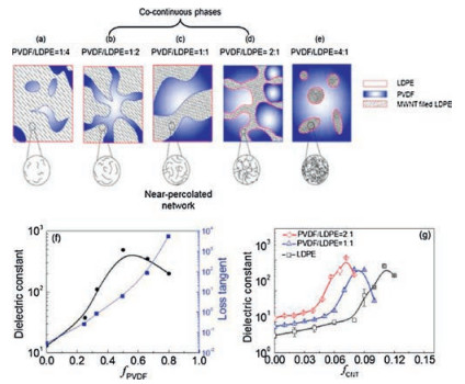
Besides the hybrid filler, the confine dispersion of nanocarbons can be also achieved by adopting biphasic polymer blends as the matrix [68-72]. It has been demonstrated that the percolation threshold of conductive composites can be substantially reduced by confining carbon nanomaterials in any one of the phases of a cocontinuous biphasic polymer blend or at the interface. Yuan et al. [68] applied this concept onto dielectric composites to pursue high-k via establishing near-percolated networks in only one phase of biphasic polymer blends. They demonstrated a CNT-filled low density polyethylene (LDPE)/PVDF composite. Images of SEM together with TEM confirmed the remarkable selective localization of CNTs in the LDPE phase [68]. Based on such selective location, a 3-D double percolated structure can form in CNT-LDPE/PVDF composites once two requirements are satisfied: ⅰ) The matrix is a co-continuous system (Fig. 7b-d). ⅱ) The CNTs are preferentially localized in LDPE phase and form a 3-D percolated network (Fig. 7d). Therefore, if the total CNT loading based on the entire polymer blends is fixed, the dielectric constant (at 1 Hz) of the composites increases based on the formation of near-percolated network of CNTs in LDPE phase (Fig. 7f) as a result of the shrinkage of LDPE phases with increasing PVDF content. The formed double percolation significantly reduces the percolation threshold in biphasic polymer composites but result in a similar k level as compared to the single polymer composites (Fig. 7g). This strategy allows for forming effective near-percolated networks with less nanotubes but without sacrificing the high-k values in the composites.

|
Download:
|
| Fig. 7. (a-e) Schematic image for the microstructure evolution of biphasic polymer composites with increasing volume ratio of PVDF/LDPE. (f) Dependence of the dielectric constant (black line) and loss tangent (blue line) on the PVDF content in polymer blends. The total CNTcontent based on the entire polymer blends is fixed at 8.0 vol%. (g) Dependence of the dielectric constant of biphasic polymer composites on the CNT content. Reproduced with permission [68]. Copyright 2012, American Chemical Society. | |
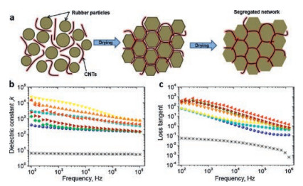
Besides the selective location of CNTs in only one phase of a biphasic polymer blend, the so-called segregated network (Fig. 8a) has been long investigated to pursue conducive polymer composites at low filler content [73]. The segregated network can be realized either by polymer latex technology [74] or by emulsion template strategy [37, 39, 75]. However, it was paid less attention in the past years to be exploited for high-k percolative composites. Recently, George et al. [74] prepared CNT/natural rubber nanocomposites with segregated network by latex stage mixing. By adding a very small amount of CNT, the nanocomposites showed remarkable improvement in mechanical, thermal, electrical and barrier properties. Segregated network of CNTs enhanced dielectric constant up to 40 while the losses increased to 1.1 at 100 Hz in the composites loaded with 5% of CNT. Luna et al. [39] proposed a new method to easily prepare high-k polymer nanocomposites using polydimethylsiloxane (PDMS) emulsion droplets as templating medium. As the droplets are greater than the carbon nanotubes they force the conducting particles to accumulate in the plateau borders. This induces a decrease of the percolation threshold and the buildup of aggregates separated by a controlled distance roughly equal to the size of the drop. For emulsion size one order of magnitude higher than the length of the carbon nanotubes, it was achieved that a much larger dielectric constant (20, 000 at 100 Hz). However, the losses are also high (~100), as shown in Fig. 8b-c.

|
Download:
|
| Fig. 8. (a) Schematic illustration of the segregated nanotube network formation in the rubber composite. Initially, the nanotubes and polymer particles are uniformly suspended in water (left). After evaporation of water, polymer particles form a close-packed morphology with nanotubes retaining at the interfaces (middle). Finally, the polymer particles interdiffuse and form a coherent film with segregated network of nanotubes. Separated nanotubes (right). Reproduced with permission [74]. Copyright 2017, Elsevier. The dependence of the (b) dielectric constant and (c) loss tangent on the frequency for CNT/PDMS nanocomposites with various concentrations: 0 wt% (cross), 0.1 wt% (sphere), 0.2 wt% (pentagon), 0.3 wt% (diamond), 0.4 wt% (down triangle), 0.5 wt% (up triangle), 0.75 wt% (left triangle), and 1 wt% (right triangle). Reproduced with permission [39]. Copyright 2015, American Chemical Society. | |
It should be noted that the CNTs are confined yet still randomly dispersed in the selected phase of the polymer blends or the boundary between polymer rich phases. The strategies for interfacial engineering are highly needed to minimize the dielectric losses, as the case of the single-matrix composites with randomly dispersed carbon nanomaterials.
4. High-k polymer composites based on self-assembly of carbon nanoparticlesSo far, the reported near-percolated networks are formed via concentrating conducting particles in polymer systems. So the phase behaviour of particles during concentration would determine the morphology of the network and consequently influencing the dielectric properties of final composites. Actually, there exists two significant transitions as concentrating a nanoparticle solution, i.e., percolation transition and the isotropic-nematic transition.
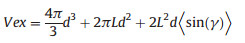
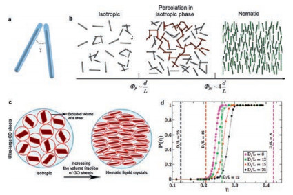
Excluded volume theory is often used to predict the percolation threshold of particles in solution. In the case of rods of diameter d and length L, the exclude volume between two particles that make an angle γ (Fig. 9a) is given by [76]:
|
(3) |

|
Download:
|
| Fig. 9. (a) Two rods in suspension which make an angle γ. Phase behaviour of (b) hard rods and (c) platelets suspensions during concentration. Image (c) is reproduced with permission [77] Copyright 2014, Royal Society of Chemistry. (d) Dependence of the percolation probability as a function of volume fraction for different aspect ratios (L and D represent the thickness and lateral diameter of platelets, respectively). The symbols and solid lines show the percolation probability while the dashed lines indicate the critical concentrations approximately corresponding to the isotropic-nematic transition. Reproduced with permission [78]. Copyright 2012, American Physical Society. | |
The contact probability of two particles scales with the ratio of this excluded volume to the actual particle volume. Assuming that the percolation threshold is inversely proportional to the contact probability, one can expect that the percolation threshold ϕp scales as
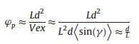
|
(4) |
Actually, during the concentration of rod solutions there is another phenomenon that would occur, i.e. isotropic-nematic transition.Atsufficiently high concentrations, therodsdisplaylong range alignment tomaximize packingentropy (Fig. 9b). The critical concentration for this isotropic-nematic transition is theoretically predicted as 
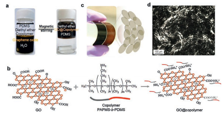
Similar scaling and conclusions would hold for platelets. However, as recently predicted by theorists, the situation may be different for impenetrable platelet particles (Fig. 9c, d) [20]. It has been shown that the isotropic-nematic transition occurs at concentration below the percolation threshold expected for randomly oriented platelets. This competition not only results in a greater percolation threshold than usually expected, but also changes in a non-intuitive way the dependence of the percolation threshold with the aspect ratio of the particles. Actually, the percolation threshold becomes almost independent on the aspect ratio of the platelets whereas the common belief is that the percolation should simply decrease with increasing the aspect ratio. A large variability of percolation thresholds has been actually reported in the literature from very low concentrations (0.1%) to relatively high concentrations (15%). Discrepancies are generally ascribed to processing difficulties, poorly controlled non-equilibirum effects. These reasons are certainly valid in several cases, but the difficulty in achieving low percolation threshold with graphene flakes maylikely result from actual physical mechanisms related to the spontaneous tendency of flakes to form a liquid crystal phase rather than forming percolating networks of randomly oriented particles [20]. The isotropic-nematic transition can thus suppress the formation of a conducting network [77]. Such competition is not favorable to develop conductive polymer composites but can be positively exploited to develop dielectric composites. The ordered liquid crystalline structure is expected to promote the formation of effective microcapacitors to afford a high dielectric constant. Yuan et al. [36] demonstrated a high-k nanocomposite based on the liquid crystal of reduced graphene oxide (rGO) in soft PDMS matrix. A diblock copolymer aminopropylmethylsiloxane-bdimethylsiloxane (PAPMS-b-PDMS) was chosen to adsorb onto graphene oxide (GO) nanosheets and stabilize their dispersion in composite precursor solutions (Fig. 10a). Such interaction is based on the electrostatic attraction between negative charges of GO nanosheets and positive ones of the copolymer (Fig. 10b). As such, the GO nanosheets continuously transferred fromwater phase into diethyl ether phase as this interaction at water/oil interface proceeded. The obtained GO suspension is well suited to prepare PDMS matrix composites (Fig. 10c), without showing any reaggregation of GO nanosheets during the process. Moreover, with increasing concentration of such GO suspension, a nematic liquid crystal phase can form even with a low GO content (Fig. 10d), which was the first report of GO liquid crystal in a nonpolar organic solvent.

|
Download:
|
| Fig. 10. (a) Photographshows the phase transferof GO flakes fromthe aqueous tothe organic phase. (b) Schematic illustrationof the electrostatic attraction betweennegative charges of GO nanosheets and positive ones of the PAPMS-b-PDMS copolymer. (c) Photograph of soft PDMS composites with GO (brown) and rGO (black) nanosheets at a loading of 1wt%. (d) Optical micrographs between crossed polarizers of GO suspensions in PDMS monomer at a concentration of 1wt%. Reproduced with permission [36]. Copyright 2015, Nature Publishing Group. | |
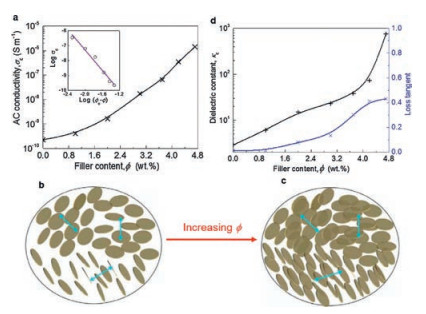
Experimentally, the competition between percolation transition and liquid crystal (LC) transition was addressed by assessing the conductivity of rGO/PDMS composites. As shown in Fig. 11a, the margin improvement of conductivity at 1.0 wt% indicates that this loading is well below the percolation threshold. However, at this rGO-PDMS mass ratio, LC transition has already taken place (Fig. 10d), indicating that the flakes with large anisotropy indeed tend to self-assemble into nematic LCs (Fig. 11b) before they form a percolated path along the direction of the conductivity measurement. Thus these results confirmed the theoretical prediction that the liquid crystal transition of platelike particles actually hinders the formation of conductive networks. This phenomenon would fundamentally change our views on the interest of graphene for conductive composites. The structure of monodomains of graphene liquid-crystalline phases largely promotes the formation of effective microcapacitors. The resultant near-percolated liquidcrystalline graphene-based composites display a dielectric constant improved by 260-fold increase as compared with the polymer matrix, while maintaining the loss tangent as low as 0.4 (at 0.1 Hz, Fig. 11d).

|
Download:
|
| Fig. 11. (a) Photographshows the phase transferof GO flakes fromthe aqueous tothe organic phase. (b) Schematic illustrationof the electrostatic attraction betweennegative charges of GO nanosheets and positive ones of the PAPMS-b-PDMS copolymer. (c) Photograph of soft PDMS composites with GO (brown) and rGO (black) nanosheets at a loading of 1wt%. (d) Optical micrographs between crossed polarizers of GO suspensions in PDMS monomer at a concentration of 1wt%. Reproduced with permission [36]. Copyright 2015, Nature Publishing Group. | |
5. Conclusions and outlook
High-k polymer composite materials are receiving tremendous attention and research interest due to their potential applications in diverse electrical and electronic devices. To enhance the dielectric constant at low filler loading and retain the low losses and flexibility of polymer matrices, establishing near-percolated network of conducting filler is a promising approach if the interfacial properties of composites are well controlled. Up to now, several general strategies towards high-k polymer composites have been developed based on carbon nanoparticles, such as randomly dispersion, confined dispersion, and self-assembly of carbon nanoparticles. The dielectric properties of percolative composites are found to be largely determined by the size, shape, and spatial arrangement of nanoparticles as well as the interfaces between polymer matrices and nanofillers [51-53]. In this review, the influence of the morphology of near-percolated network on the dielectric properties are addressed.
High-k polymer composites based on randomly dispersed carbon nanoparticles, such as CNTs and graphene, are the most studied percolative systems. Such random dispersion generally brings challenges on fine controlling the morphology of nearpercolated networks in polymer composites. In this regard, it is necessary to introduce interfacial barrier into composites by noncovalent polymer wrapping or coating the particles with a sound and integral organic or inorganic shell. Such insulating barrier is capable of preventing electron tunneling and giving rise to a desirable combination of high k and low loss at low fields. However, it fails to suppress the leakage current resulting from the tunneling at high fields. Up to now, an improved dielectric strength relative to the neat polymer matrix has not yet been reported. Improving the high-field dielectric responses of polymers by using conductive nanofillers is very hard if not impossible. This open question deserves to be paid much more attention in the future.
Confined dispersion of carbon nanoparticles changes the dielectric properties of composites by significant lowering the percolation threshold. Percolating at low filler loading well retains the flexibility of polymer matrices and makes the processing window for high k narrow. Such high sensitivity of dielectric constant with concentration is desirable for developing variable capacitor towards the application of capacitive sensing. However, it should be noted that the CNTs are confined yet still randomly dispersed in the selected location in composites. The strategies for interfacial engineering are still needed to minimize the dielectric losses.
Self-assembling of nanoparticles with large aspect ratio into ordered structure in composites indeed makes a great step towards the controllable near-percolated network. The ordered graphene liquid crystalline structure promotes the formation of microcapacitors, thus not only gives rise to a high dielectric constant and low loss simultaneously [35, 47], but also provides a large processing window for this unique combination. Aligning the locally ordered crystal domains can result in a true anisotropic composite with welled controlled structure. The dielectric properties of such anisotropic composites are highly needed to be further investigated. Meanwhile formulation and microfabrication technologies have been progressing very fast in past years. Implementing new microfabrication techniques such as ink-jet printing, 3D printing for example could help in achieving highly controlled structures with enhanced dielectric properties.
AcknowledgementsThe work on graphene liquid crystal based composites are supported by project ELENA, funded by France ANR and Solvay, and of the Labex AMADEus (No. ANR-10-LABX-0042-AMADEus).
| [1] |
Q. Chen, Y. Shen, S.H. Zhang, Q.M. Zhang, Annu. Rev. Mater. Res. 45(2015) 433-458. DOI:10.1146/annurev-matsci-070214-021017 |
| [2] |
V.K. Prateek, R.K. Thakur Gupta, Chem. Rev. 116(2016) 4260-4317. DOI:10.1021/acs.chemrev.5b00495 |
| [3] |
M. Lallart, P.J. Cottinet, D. Guyomar, L. Lebrun, J. Polym. Sci. Pol. Phys. 50(2012) 523-535. |
| [4] |
Z.H. Yao, Z. Song, H. Hao, et al., Adv. Mater. 29(2017) 1601727. DOI:10.1002/adma.v29.20 |
| [5] |
E. Baer, L. Zhu, Macromolecules 50(2017) 2239-2256. DOI:10.1021/acs.macromol.6b02669 |
| [6] |
A. Mannodi-Kanakkithodi, G.M. Treich, T.D. Huan, et al., Adv. Mater. 28(2016) 6277-6291. DOI:10.1002/adma.201600377 |
| [7] |
B. Neese, B. Chu, S.G. Lu, et al., Science 321(2008) 821-823. DOI:10.1126/science.1159655 |
| [8] |
Q. Li, G.Z. Zhang, X.S. Zhang, et al., Adv. Mater. 27(2015) 2236-2241. DOI:10.1002/adma.201405495 |
| [9] |
Q.M. Zhang, H.F. Li, M. Poh, et al., Nature 419(2002) 284-287. DOI:10.1038/nature01021 |
| [10] |
C. Park, J.H. Kang, J.S. Harrison, R.C. Costen, S.E. Lowther, Adv. Mater. 20(2008) 2074-2079. DOI:10.1002/(ISSN)1521-4095 |
| [11] |
L.J. Romasanta, M.A. Lopez-Manchado, R. Verdejo, Prog. Polym. Sci. 51(2015) 188-211. DOI:10.1016/j.progpolymsci.2015.08.002 |
| [12] |
C. Choi, J.M. Lee, S.H. Kim, et al., Nano Lett. 16(2016) 7677-7684. DOI:10.1021/acs.nanolett.6b03739 |
| [13] |
W. Hu, X. Niu, R. Zhao, Q. Pei, Appl. Phys. Lett. 102(2013) 083303. DOI:10.1063/1.4794143 |
| [14] |
D.J. Lipomi, M. Vosgueritchian, B.C.K. Tee, et al., Nature Nanotech. 6(2011) 788-792. DOI:10.1038/nnano.2011.184 |
| [15] |
Z.M. Dang, J.K. Yuan, J.W. Zha, et al., Prog. Mater. Sci. 57(2012) 660-723. DOI:10.1016/j.pmatsci.2011.08.001 |
| [16] |
T. Zhou, J.W. Zha, R.Y. Cui, et al., ACS Appl. Mater. Interfaces 3(2011) 2184-2188. DOI:10.1021/am200492q |
| [17] |
X. Huang, P. Jiang, Adv. Mater. 27(2015) 546-554. DOI:10.1002/adma.v27.3 |
| [18] |
Z.M. Dang, J.K. Yuan, S.H. Yao, R.J. Liao, Adv. Mater. 25(2013) 6334-6365. DOI:10.1002/adma.v25.44 |
| [19] |
Y. Shen, Y.H. Lin, Q.M. Zhang, MRS Bull. 40(2015) 753-759. DOI:10.1557/mrs.2015.199 |
| [20] |
Y. Shen, D.S. Shen, X. Zhang, et al., J. Mater. Chem. A 4(2016) 8359-8365. DOI:10.1039/C6TA02186G |
| [21] |
Z.M. Dang, T. Zhou, S.H. Yao, et al., Adv. Mater. 21(2009) 2077-2082. DOI:10.1002/adma.v21:20 |
| [22] |
Z. Dou, W. Liu, T. Lin, K. Zhou, L. Hang, Appl. Phys. Lett. 110(2017) 133902. DOI:10.1063/1.4979407 |
| [23] |
G.Y. Wang, X.Y. Huang, P.K. Jiang, J. Mater. Chem. C 5(2017) 3112-3120. DOI:10.1039/C7TC00387K |
| [24] |
D. Zhang, X.F. Zhou, J. Roscow, et al., Sci. Rep. 7(2017) 45179. DOI:10.1038/srep45179 |
| [25] |
H.A. Avila, L.A. Ramajo, M.S. Goes, et al., ACS Appl. Mater. Interfaces 5(2013) 505-510. DOI:10.1021/am302646z |
| [26] |
G.Y. Wang, X.Y. Huang, P.K. Jiang, ACS Appl. Mater. Interfaces 9(2017) 7547-7555. DOI:10.1021/acsami.6b14454 |
| [27] |
P.H. Hu, Y. Shen, Y.H. Guan, et al., Adv. Funct. Mater. 24(2014) 3172-3178. DOI:10.1002/adfm.201303684 |
| [28] |
P.H. Hu, Y. Song, H.Y. Liu, et al., J. Mater. Chem. A 1(2013) 1688-1693. DOI:10.1039/C2TA00948J |
| [29] |
Q. Li, L. Chen, M.R. Gadinski, et al., Nature 523(2015) 576-579. DOI:10.1038/nature14647 |
| [30] |
F.H. Liu, Q. Li, J. Cui, et al., Adv. Funct. Mater. 27(2017) 1606292. DOI:10.1002/adfm.v27.20 |
| [31] |
V. Tomer, E. Manias, C.A. Randall, J. Appl. Phys. 110(2011) 044107. DOI:10.1063/1.3609082 |
| [32] |
S. Roy, P. Thakur, N.A. Hoque, B. Bagchi, S. Das, RSC Adv. 6(2016) 21881-21894. DOI:10.1039/C6RA00864J |
| [33] |
C.W. Nan, Prog. Mater. Sci. 37(1993) 1-116. DOI:10.1016/0079-6425(93)90004-5 |
| [34] |
J.K. Yuan, S. Yao, W. Li, A. Sylvestre, J. Bai, J. Phys. Chem. C 118(2014) 22975-22983. DOI:10.1021/jp508206t |
| [35] |
J.K. Yuan, A. Luna, W. Neri, et al., Nat. Commun. 6(2015) 8700. DOI:10.1038/ncomms9700 |
| [36] |
A.L. Efros, B.I. Shklovskii, Phys. Status Solidi B 76(1976) 475-485. DOI:10.1002/(ISSN)1521-3951 |
| [37] |
A. Luna, M. Pruvost, J.K. Yuan, et al., Langmuir 33(2017) 4528-4536. DOI:10.1021/acs.langmuir.6b04185 |
| [38] |
C.W. Nan, Y. Shen, J. Ma, Annu Rev., Mater. Res. 40(2010) 131-151. DOI:10.1146/annurev-matsci-070909-104529 |
| [39] |
A. Luna, J. Yuan, W. Neri, et al., Langmuir 31(2015) 12231-12239. DOI:10.1021/acs.langmuir.5b02318 |
| [40] |
F. Carpi, D. De Rossi, R. Kornbluh, R. Pelrine, P. Sommer-Larsen, Dielectric Elastomers as Electromechanical Transducers, Elsevier, Amsterdam(2008). |
| [41] |
Z.M. Dang, Y.H. Lin, C.W. Nan, Adv. Mater. 15(2003) 1625-1629. DOI:10.1002/(ISSN)1521-4095 |
| [42] |
G. Kofod, S. Risse, H. Stoyanov, et al., ACS Nano 5(2011) 1623-1629. DOI:10.1021/nn103097q |
| [43] |
L.L. Sun, B. Li, Y. Zhao, G. Mitchell, W.H. Zhong, Nanotechnology 21(2010) 305702. DOI:10.1088/0957-4484/21/30/305702 |
| [44] |
L. Wang, Z.M. Dang, Appl. Phys. Lett. 87(2005) 042903. DOI:10.1063/1.1996842 |
| [45] |
J.K. Yuan, W.L. Li, S.H. Yao, et al., Appl. Phys. Lett. 98(2011) 032901. DOI:10.1063/1.3544942 |
| [46] |
F. He, S. Lau, H.L. Chan, J.T. Fan, Adv. Mater. 21(2009) 710-715. DOI:10.1002/adma.v21:6 |
| [47] |
N. Yousefi, X. Sun, X. Lin, et al., Adv. Mater. 26(2014) 5480-5487. DOI:10.1002/adma.201305293 |
| [48] |
W. Ding, A. Eitan, F.T. Fisher, et al., Nano Lett. 3(2003) 1593-1597. DOI:10.1021/nl0345973 |
| [49] |
Z.M. Dang, M.S. Zheng, J.W. Zha, Small 12(2016) 1688-1701. DOI:10.1002/smll.v12.13 |
| [50] |
Q. Chen, P.Y. Du, L. Jin, W.J. Weng, G.R. Han, Appl. Phys. Lett. 91(2007) 022912. DOI:10.1063/1.2757131 |
| [51] |
G. Chen, J. Lu, D. Wu, Mater. Chem. Phys. 104(2007) 240-243. DOI:10.1016/j.matchemphys.2007.01.011 |
| [52] |
X. Gao, S. Zhang, F. Mai, et al., J. Mater. Chem. 21(2011) 6401-6408. DOI:10.1039/c0jm04543h |
| [53] |
M. Panda, V. Srinivas, A.K. Thakur, Appl. Phys. Lett. 93(2008) 242908. DOI:10.1063/1.3054163 |
| [54] |
S.H. Yao, Z.M. Dang, M.J. Jiang, H.P. Xu, J.B. Bai, Appl. Phys. Lett. 91(2007) 212901. DOI:10.1063/1.2817746 |
| [55] |
W. Li, J. Yuan, Y. Lin, et al., Carbon 51(2013) 355-364. DOI:10.1016/j.carbon.2012.08.064 |
| [56] |
Z.M. Dang, L. Wang, Y. Yin, Q. Zhang, Q.Q. Lei, Adv. Mater. 19(2007) 852-857. DOI:10.1002/(ISSN)1521-4095 |
| [57] |
J.K. Yuan, S.H. Yao, Z.M. Dang, et al., J. Phys. Chem. C 115(2011) 5515-5521. DOI:10.1021/jp1117163 |
| [58] |
C. Wu, X. Huang, L. Xie, J. Yu, P. Jiang, J. Mater. Chem. 21(2011) 17729-17736. DOI:10.1039/c1jm12903a |
| [59] |
Z.N. Zhang, J. Zhang, P. Chen, et al., Carbon 44(2006) 692-698. DOI:10.1016/j.carbon.2005.09.027 |
| [60] |
T. Zhou, J.W. Zha, Y. Hou, et al., ACS Appl. Mater. Interfaces 3(2011) 4557-4560. DOI:10.1021/am201454e |
| [61] |
C. Wu, X. Huang, X. Wu, et al., Compos. Sci. Technol. 72(2012) 521-527. DOI:10.1016/j.compscitech.2011.12.014 |
| [62] |
S. Zhang, H. Wang, G. Wang, Z. Jiang, Appl. Phys. Lett. 101(2012) 012904. DOI:10.1063/1.4733723 |
| [63] |
H. Liu, Y. Shen, Y. Song, et al., Adv. Mater. 23(2011) 5104-5108. DOI:10.1002/adma.201102079 |
| [64] |
Z. Chen, L.Y. Xie, X.Y. Huang, S.T. Li, P.K. Jiang, Carbon 95(2015) 895-903. DOI:10.1016/j.carbon.2015.09.020 |
| [65] |
J.K. Yuan, S. Yao, W. Li, A. Sylvestre, J. Bai, J. Phys. Chem. C 121(2017) 12063-12070. DOI:10.1021/acs.jpcc.7b03372 |
| [66] |
A. Dichiara, J.K. Yuan, S.H. Yao, A. Sylvestre, J. Bai, J. Nanosci. Nanotechnol. 12(2012) 6935-6940. DOI:10.1166/jnn.2012.6573 |
| [67] |
H. Zhao, M.H. Yang, D.L. He, J.B. Bai, J. Mater. Chem. C 4(2016) 8911-8919. DOI:10.1039/C6TC02386J |
| [68] |
J.K. Yuan, S.H. Yao, A. Sylvestre, J. Bai, J. Phys. Chem. C 116(2012) 2051-2058. DOI:10.1021/jp210872w |
| [69] |
X.D. Zhao, J. Zhao, J.P. Cao, et al., Mater. Des. 56(2014) 807-815. DOI:10.1016/j.matdes.2013.11.073 |
| [70] |
X.D. Zhao, J.P. Cao, J. Zhao, G.H. Hu, Z.M. Dang, J. Mater. Chem. A 2(2014) 10614-10622. DOI:10.1039/c4ta01214c |
| [71] |
J.P. Cao, J. Zhao, X.D. Zhao, et al., Compos. Sci. Technol. 89(2013) 142-148. DOI:10.1016/j.compscitech.2013.09.024 |
| [72] |
X.D. Zhao, J. Zhao, J.P. Cao, et al., J. Phys. Chem. B 117(2013) 2505-2515. DOI:10.1021/jp310021r |
| [73] |
H. Pang, L. Xu, D.X. Yan, Z.M. Li, Prog. Poly. Sci. 39(2014) 1908-1933. DOI:10.1016/j.progpolymsci.2014.07.007 |
| [74] |
N. George, P.K. Bipinbal, B. Bhadran, A. Mathiazhagan, R. Joseph, Polymer 112(2017) 264-277. DOI:10.1016/j.polymer.2017.01.082 |
| [75] |
J.C. Grunlan, A.R. Mehrabi, M.V. Bannon, J.L. Bahr, Adv. Mater. 16(2004) 150-153. DOI:10.1002/(ISSN)1521-4095 |
| [76] |
E. Charlaix, J. Phys. A:Math Gen. 19(1986) L533-L536. DOI:10.1088/0305-4470/19/9/013 |
| [77] |
S. Naficy, R. Jalili, S.H. Aboutalebi, et al., Mater. Horiz. 1(2014) 326-331. DOI:10.1039/C3MH00144J |
| [78] |
M. Mathew, T. Schilling, M. Oettel, Phys. Rev. E 85(2012) 061407. DOI:10.1103/PhysRevE.85.061407 |