0 引言
中俄东线天然气管道是中国首条大口径、高压力和高钢级的长距离天然气输送管道,目前黑河-长岭段已开工建设,其干线全长737 km,设计输气能力380×108 m3/a,设计压力12 MPa,管径1 422 mm,全线采用X80M钢管[1]。根据不同的地区等级和设计系数,全线钢管壁厚有21.4、25.7和30.8 mm等3种。中俄东线天然气管道工程(黑河-长岭段)D1422管道全面推广应用全自动焊接[2-6],为了提高全自动焊接连续作业效率,减少沟下连头口数量,管道尽量采取沟上焊接方式。待钢管焊接连成“长龙”后,再进行整体下沟作业。由于沉管下沟方法具有施工组织容易、可减少临时征地、保证作业人员及设备安全、操作简便和施工效率高等优点[7-8],所以中俄东线天然气管道工程(黑河-长岭段)采用沉管下沟的施工方式。
管道在沉管下沟过程中将发生明显大位移变形,并经历高应力状态,这对管道安全和质量有潜在影响。因此,笔者对沉管下沟过程进行研究,详细分析该过程中潜在危险因素并提出控制措施,以指导和保障中俄东线天然气管道安全施工。
1 沉管下沟简介沉管下沟是指沿管道开挖管沟,利用管道自身重力缓慢将管道自然下沉到管沟内的施工方法,宜采用双侧沉管下沟方式。双侧沉管下沟是在管道轴线两侧布置挖掘机同时开挖管沟,利用管道自身重力缓慢将管道自然降落到管沟内的施工方法[9]。为了防止管道局部滑坡和位移,在开挖过程中,应保证管道轴线两侧挖掘机开挖进度同步。
双侧沉管下沟时,可采用双侧单向沉管下沟或双侧背向沉管下沟施工方法。双侧单向沉管下沟是从管段的一端开始,采用双侧沉管下沟方式,逐步向另一端进行沉管下沟作业,见图 1。双侧背向沉管下沟是从管段中间一点开始,采用双侧沉管下沟方式,逐步同时向两端进行沉管下沟作业,见图 2。

|
| 图 1 双侧单向沉管下沟俯视图 Fig.1 Top view of the double-side one-way pipeline sinking and lowering |

|
| 图 2 双侧背向沉管下沟俯视图 Fig.2 Top view of the double-side opposite-direction pipeline sinking and lowering |
2 模拟计算方法
采用ANSYS软件计算分析中俄东线天然气管道工程沉管下沟过程。
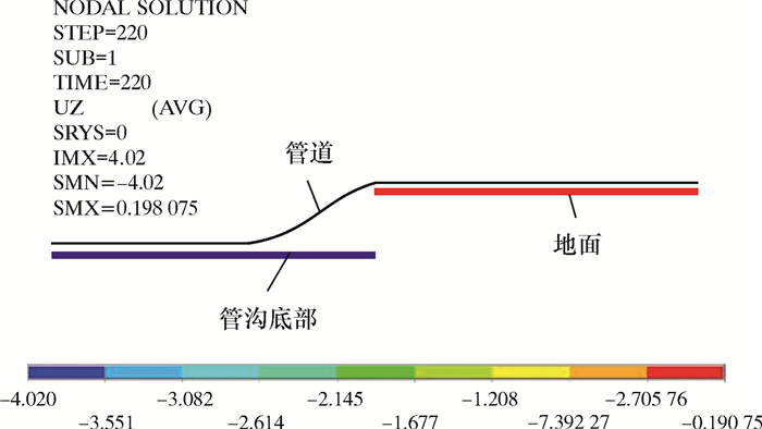
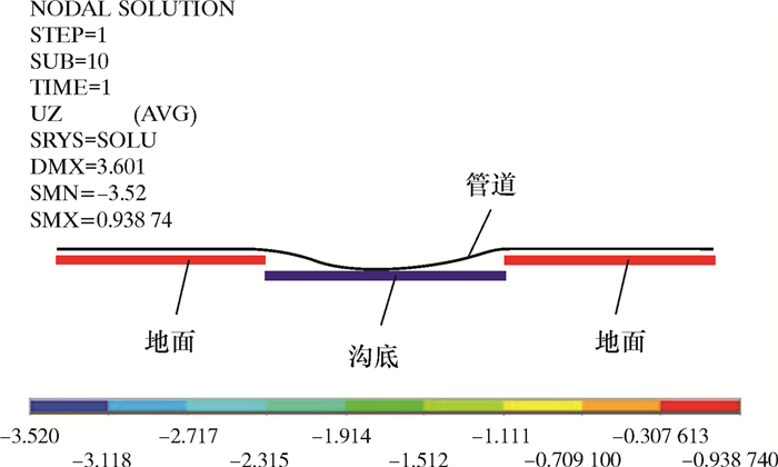
管道用PIPE20三维薄壁管单元模拟[10-12],管材采用线弹性材料模拟[13-14]。其弹性模量为210 GPa,泊松比为0.3,X80钢最小屈服强度为555 MPa,管段两端采用自由约束。下沟过程中土体对管道的支撑和摩擦作用采用CONTAC52接触单元模拟,接触单元法向刚度935.3 kN/m。假设管道相对于土体水平位移2 mm时开始滑动,滑动摩擦因数0.5。假设下沟管段为长直管道,从起始下沟点下沟对管段端部无影响。采用多载荷步法进行计算,从起始下沟点开始,逐步施加位移载荷,模拟沿管道轴向的管沟开挖过程。计算时考虑管道的几何非线性。建立的有限元模型如图 3和图 4所示。
|
| 图 3 双侧单向沉管下沟有限元模型 Fig.3 Finite element model of the double-side one-way pipeline sinking and lowering |
|
| 图 4 双侧背向沉管下沟有限元模型 Fig.4 Finite element model of the double-side opposite- direction pipeline sinking and lowering |
3 沉管下沟规律分析 3.1 双侧单向沉管下沟
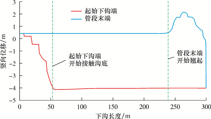
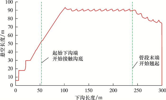
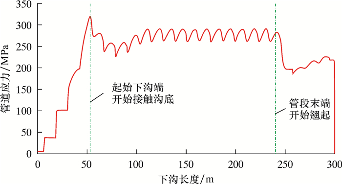
算例:外径1 422 mm、壁厚21.4 mm、X80钢级,管沟深度4.0 m,下沟直管段长度300 m。管道下沟前放置于地面的土墩上,土墩高度0.5 m,土墩位于每根钢管的中点,每根钢管长12 m,相邻土墩间距12 m。计算得到的直管段双侧单向沉管下沟过程中,起始下沟端和管段末端竖向位移、悬空长度和计算管段最大应力的变化规律如图 5~图 7所示。其中,以地面为高程0点。从图 5~图 7可发现:
|
| 图 5 双侧单向沉管下沟过程中起始下沟端和管段末端竖向位移变化规律 Fig.5 Variation of vertical displacement of the starting lowering end and the end of the pipe during the process of the double-side one-way pipeline sinking and lowering |
|
| 图 6 双侧单向沉管下沟过程中悬空长度变化规律 Fig.6 Variation of suspending length during the process of the double-side one-way pipeline sinking and lowering |
|
| 图 7 双侧单向沉管下沟过程中计算管段最大应力变化规律 Fig.7 The maximum stress variation of the calculated pipeline section during the process of the double-side one-way pipeline sinking and lowering |
(1) 有支墩情况下起始下沟端和管段末端竖向位移、计算管段最大应力和悬空长度呈阶梯状或波动状变化。
(2) 管道悬空长度在下沟开始后一直呈增大趋势,后逐步稳定;当下沟进行至管段末端附近时,悬空长度逐渐减小;在管道全部放置于沟底后,悬空长度变为0。
(3) 管道应力自沉管下沟开始后逐渐增大,在起始下沟端开始接触沟底时达到最大,然后先减小后增大并趋于稳定;当下沟过程进行至管段末端附近时,管道应力逐渐减小后略有增大,最后当管段全部进入管沟后,管道应力变为0。
(4) 当下沟进行至管段末端时,末端将翘起。
3.2 双侧背向沉管下沟算例:外径1 422 mm、壁厚21.4 mm、X80钢级,管沟深度4.0 m,下沟直管段长度600 m。管道下沟前置于地面土墩上,土墩高0.5 m,位于每根钢管的中点,单根钢管长12 m,相邻土墩间距12 m。假设双侧背向沉管下沟从计算管段的中点开始,起始下沟点左右两侧开挖进度相同,则起始下沟点左右两侧的下沟规律相同。因此只分析一侧的下沟规律,起始下沟点一侧下沟长度300 m。
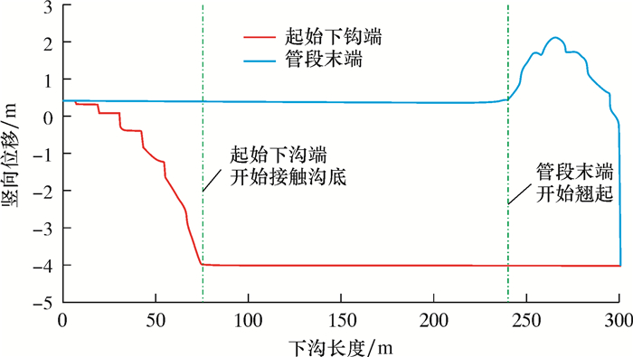
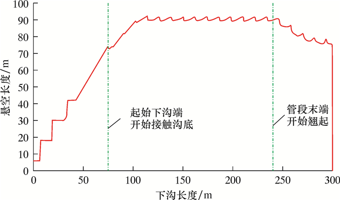
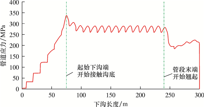
计算得到的直管段双侧背向沉管下沟过程中,起始下沟点和管段末端竖向位移、计算管段最大应力、悬空长度的变化规律如图 8~图 10所示。其中,下沟长度和悬空长度分别指起始下沟点一侧的下沟半长和悬空半长。
|
| 图 8 双侧背向沉管下沟过程中起始下沟点和管段末端竖向位移变化规律 Fig.8 Variation of vertical displacement of the starting lowering point and the end of the pipe during the process of the double-side opposite-direction pipeline sinking and lowering |
|
| 图 9 双侧背向沉管下沟过程中悬空长度变化规律 Fig.9 Variation of suspending length during the process of the double-side opposite-direction pipeline sinking and lowering |
|
| 图 10 双侧背向沉管下沟过程中计算管段最大应力变化规律 Fig.10 The maximum stress variation of the calculated pipeline section during the process of the double-side opposite-direction pipeline sinking and lowering |
从图 8~图 10可以看出,直管段双侧背向沉管下沟时,管道最大应力同样发生在起始下沟点开始接触沟底时,其他规律与双侧单向沉管下沟类似。
3.3 双侧单向和双侧背向沉管下沟对比(1) 对于管道最大应力,双侧背向沉管下沟方式大于双侧单向沉管下沟方式。
(2) 对于起始下沟端(点)开始接触沟底时的悬空长度(或半长),双侧背向沉管下沟方式大于双侧单向沉管下沟方式。
3.4 沉管下沟典型状态(1) 起始下沟端(点)开始接触沟底时的状态,此时管道应力最大。
(2) 悬空长度和管道应力达到稳定时的状态,此状态持续时间最长。
(3) 管段末端翘起高度最大时的状态,此状态存在安全隐患。
4 实例计算 4.1 沉管下沟计算结果采用ANSYS有限元软件,在沉管下沟规律分析的基础上,对中俄东线D1422×21.4 mm、D1422×25.7 mm和D1422×30.8 mm等3种管道沉管下沟进行计算。结合沉管下沟过程中的3个典型状态,分别给出起始下沟端(点)开始接触沟底(即管道应力最大)时的管道应力、悬空长度与管道应力稳定时的管道应力及管段末端最大翘起高度。
中俄东线管沟深度一般在5 m以内,为便于工程应用,分别给出管沟深度3.0、3.5、4.0、4.5和5.0 m时的计算结果。计算时,考虑管道下沟前地面上的土墩高度0.5 m。双侧单向沉管下沟计算结果见表 1,双侧背向沉管下沟计算结果见表 2。
| 管沟深度/m | D1422×21.4 mm管道 | D1422×25.7 mm管道 | D1422×30.8 mm管道 | ||||||||
| 接触沟底时管道应力/MPa | 稳定时管道应力/MPa | 最大翘起高度/m | 接触沟底时管道应力/MPa | 稳定时管道应力/MPa | 最大翘起高度/m | 接触沟底时管道应力/MPa | 稳定时管道应力/MPa | 最大翘起高度/m | |||
| 3.0 | 258.8 | 238.5 | 1.6 | 253.9 | 234.1 | 1.6 | 249.3 | 230.0 | 1.5 | ||
| 3.5 | 294.2 | 265.0 | 1.9 | 288.5 | 260.1 | 1.8 | 283.6 | 255.7 | 1.8 | ||
| 4.0 | 318.6 | 289.8 | 2.1 | 317.6 | 284.6 | 2.1 | 315.3 | 280.1 | 2.0 | ||
| 4.5 | 325.2 | 313.1 | 2.4 | 327.2 | 307.9 | 2.3 | 331.1 | 303.6 | 2.3 | ||
| 5.0 | 346.0 | 335.0 | 2.6 | 343.8 | 330.1 | 2.5 | 341.8 | 326.1 | 2.5 | ||
| 管沟深度/m | D1422×21.4 mm管道 | D1422×25.7 mm管道 | D1422×30.8 mm管道 | ||||||||
| 接触沟底时管道应力/MPa | 稳定时管道应力/MPa | 最大翘起高度/m | 接触沟底时管道应力/MPa | 稳定时管道应力/MPa | 最大翘起高度/m | 接触沟底时管道应力/MPa | 稳定时管道应力/MPa | 最大翘起高度/m | |||
| 3.0 | 270.3 | 238.5 | 1.6 | 266.2 | 234.1 | 1.6 | 261.7 | 230.0 | 1.5 | ||
| 3.5 | 301.2 | 265.0 | 1.9 | 295.3 | 260.1 | 1.8 | 289.7 | 255.7 | 1.8 | ||
| 4.0 | 337.6 | 289.8 | 2.1 | 331.6 | 284.6 | 2.1 | 325.6 | 280.1 | 2.0 | ||
| 4.5 | 352.6 | 313.1 | 2.4 | 354.8 | 307.9 | 2.3 | 349.2 | 303.6 | 2.3 | ||
| 5.0 | 364.8 | 335.0 | 2.6 | 359.9 | 330.1 | 2.5 | 357.4 | 326.1 | 2.5 | ||
4.2 沉管下沟应力状态校核
参考油气输送管道沉管下沟施工规范[9]和PRCI关于管道下沟的研究成果[15],沉管下沟过程中的许用应力取80%最小屈服强度,则中俄东线X80管道沉管下沟许用应力为444 MPa。
由此可得:中俄东线D1422×21.4 mm、D1422×25.7 mm和D1422×30.8 mm管道,当管沟深度在5 m以内时,采用双侧单向和双侧背向沉管下沟过程中的应力均在规范要求的许用应力以内;中俄东线D1422×21.4 mm、D1422×25.7 mm和D1422×30.8 mm管道,当管沟深度在5 m以内时,可采用双侧单向或双侧背向沉管下沟的施工方式。
5 沉管下沟控制措施通过计算分析,当沉管下沟进行至管段末端时,管道端部将翘起,这可能造成管道侧向摆动,存在安全隐患。为了避免管道末端翘起导致管道侧向摆动而发生危险,在管沟开挖至管道端部附近时,应根据现场施工条件采取以下两种控制措施。
5.1 措施1在管段端部布置临时固定墩,如图 11所示。

|
| 图 11 临时固定墩布置示意图 Fig.11 Schematic diagram of layout of the temporary fixed pier |
但应注意以下问题。
(1) 临时固定墩只限制管道侧向摆动,不限制端部翘起。
(2) 临时固定墩应有足够的稳定性,以防止管道端部侧向摆动。
(3) 临时固定墩的高度不小于表 3中的高度。在管沟开挖边界距离管段端部的距离达到表 3中“布置临时固定墩时管沟开挖边界距离管段端部的最小距离”之前,即应开始布置临时固定墩。
| 管沟深度/m | 临时固定墩高度/m | 布置临时固定墩时管沟开挖边界距管段端部的最小距离/m |
| 3.0 | 3.1 | 68 |
| 3.5 | 3.4 | 69 |
| 4.0 | 3.6 | 70 |
| 4.5 | 3.9 | 72 |
| 5.0 | 4.1 | 73 |
5.2 措施2
管段末段分层开挖,使端部相对于地面的最大翘起高度不超过0.6 m,如图 12所示。应注意以下问题。
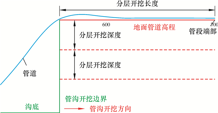
|
| 图 12 分层开挖示意图 Fig.12 Schematic diagram of layered excavation |
(1) 有支墩时,第1层开挖深度不大于0.7 m,加上支墩高度0.5 m,相当于第1层开挖后管道下沉1.2 m;除第1层外,其余每层开挖深度都不大于1.4 m。
(2) 开挖宽度即管沟宽度。
(3) 沿管道轴向的分层开挖长度不小于80 m。
分层开挖深度和长度如图 12所示。
6 结论(1) 建立了中俄东线沉管下沟有限元模型,计算分析了直管段沉管下沟规律,总结了沉管下沟过程中的3个典型状态。
(2) 采用ANSYS有限元软件,计算分析了中俄东线D1422×21.4 mm、D1422×25.7 mm和D1422×30.8 mm直管段管墩高度0.5 m、沉管下沟管沟深度2.5、3.0、3.5、4.0、4.5和5.0 m时的管道应力。
(3) 计算结果表明,中俄东线D1422×21.4 mm、D1422×25.7 mm和D1422×30.8 mm直管道可采用双侧单向或双侧背向沉管下沟施工方式。当管沟深度大于3.5 m时,建议分层开挖管沟和沉管。
(4) 为了避免下沟管段末端翘起导致管道侧向摆动而发生危险,在计算分析的基础上,提出了两种控制措施。
| [1] |
张振永, 张文伟, 周亚薇, 等. 中俄东线OD1422 mm埋地管道的断裂控制设计[J]. 油气储运, 2017, 36(9): 1059-1064. ZHANG Z Y, ZHANG W W, ZHOU Y W, et al. The fracture control design of the OD1422 mm buried pipeline in China-Russia Eastern Gas Pipeline[J]. Oil & Gas Storage and Transportation, 2017, 36(9): 1059-1064. |
| [2] |
隋永莉. 长输油气管道高强度管线钢管现场焊接技术[J]. 电焊机, 2014, 44(5): 27-32. SUI Y L. High strength line-pipe girth welding technology of oil and gas transmission pipeline[J]. Electric Welding Mechine, 2014, 44(5): 27-32. |
| [3] |
吴宏, 周剑琴. 国内大口径、高钢级管道焊接及焊缝检测技术现状[J]. 油气储运, 2017, 36(1): 21-27. WU H, ZHOU J Q. Current status of welding and weld testing technologies for large-diameter high-grade pipelines in China[J]. Oil & Gas Storage and Transportation, 2017, 36(1): 21-27. |
| [4] |
李强, 王良军, 刘新凌, 等. 焊接拘束条件下油气管道焊接接头的断裂韧性[J]. 油气储运, 2017, 36(4): 398-402. LI Q, WANG L J, LIU X L, et al. Fracture toughness of welding joints in oil and gas pipelines under welding restraint conditions[J]. Oil & Gas Storage and Transportation, 2017, 36(4): 398-402. |
| [5] |
唐青, 熊娟, 张文艳. 油气管道河流穿越段外防腐层检测系统改进与应用[J]. 钻采工艺, 2018, 41(4): 107-108. TANG Q, XIONG J, ZHANG W Y. Improvement and application of detection system for outer anti-corrosion layer of oil and gas pipeline river crossing section[J]. Drilling & Production Technology, 2018, 41(4): 107-108. DOI:10.3969/J.ISSN.1006-768X.2018.04.34 |
| [6] |
岳明, 汪运储. 页岩气井下油管和地面集输管道腐蚀原因及防护措施[J]. 钻采工艺, 2018, 41(5): 125-127. YUE M, WANG Y C. Corrosion causes and protective measures of shale gas underground pipeline and ground gathering pipeline[J]. Drilling & Production Technology, 2018, 41(5): 125-127. DOI:10.3969/J.ISSN.1006-768X.2018.05.38 |
| [7] |
王付会, 练章华, 林铁军. 双侧沉管在水网地段应力分析及数值模拟[J]. 石油机械, 2015, 43(7): 116-120. WANG F H, LIAN Z H, LIN T J. Theoretical analysis and numerical simulation of pipeline stress with lowering pipeline on both side water network area[J]. China Petroleum Machinery, 2015, 43(7): 116-120. |
| [8] |
康万平, 王宇, 李战宏. 沉管技术在长输管道河谷段的施工应用[J]. 油气储运, 2010, 29(7): 550-552. KANG W P, WANG Y, LI Z H. Application of pipe sinking technique in valley pipeline construction[J]. Oil & Gas Storage and Transportation, 2010, 29(7): 550-552. |
| [9] |
中国石油天然气管道局.油气输送管道沉管下沟施工规范: Q/SY GDJ 0387-2014[S].北京: [出版者不详], 2015. China Petroleum Pipeline Engineering Company. Specification for oil and gas transportation pipeline sinking and lowering-in: Q/SY GDJ 0387-2014[S]. Beijing: [s.n.], 2015. |
| [10] |
刘玉卿, 钟桂香, 赵子峰. 油气管道规范中弹性敷设弯曲应力公式的改进[J]. 油气储运, 2014, 33(4): 429-432. LIU Y Q, ZHONG G X, ZHAO Z F. Improvement of elastic laying bending stress formula in oil and gas pipeline standard[J]. Oil & Gas Storage and Transportation, 2014, 33(4): 429-432. |
| [11] |
刘玉卿, 余志峰, 佟雷, 等. 基于轴向应力监测数据的管道应力状态预警模型[J]. 石油机械, 2018, 46(6): 105-109. LIU Y Q, YU Z F, TONG L, et al. Early warning model of pipeline stress state based on axial stress monitoring data[J]. China Petroleum Machinery, 2018, 46(6): 105-109. |
| [12] |
刘玉卿, 仝雷, 余志峰, 等. 西气东输二线穿越处管道位移分析及解决方案[J]. 油气储运, 2018, 37(12): 1-6. LIU Y Q, TONG L, YU Z F, et al. Analysis and solution on the displacement of the second west-to-eastgas pipeline at the crossing position[J]. Oil & Gas Storage and Transportation, 2018, 37(12): 1-6. |
| [13] |
孙训方, 方孝淑, 关来泰, 等. 材料力学(Ⅰ)[M]. 北京: 高等教育出版社, 2013: 27-38.
|
| [14] |
帅健. 管线力学[M]. 北京: 科学出版社, 2010: 1-8.
|
| [15] |
LIU M, DEGEN C, WANG Y Y. Management of pipeline lifting and lowering-in stresses(Phase Ⅰ through Phase Ⅲ)[R]//Pipeline Research Council International Catalog No. PR-186-124510-M03, CNST-2-2, September, 2016.
|


