文章信息
- 韩东涛, 曹宇, 佟晟
- HAN Dongtao, CAO Yu, TONG Sheng
- 基于微分运动学的林用轮腿底盘越障误差研究
- Research on the motion deviation of the active gait chassis cross the obstacle used in the forestry based on differential kinematics
- 森林与环境学报,2019, 39(5): 554-560.
- Journal of Forest and Environment,2019, 39(5): 554-560.
- http://dx.doi.org/10.13324/j.cnki.jfcf.2019.05.015
-
文章历史
- 收稿日期: 2019-06-27
- 修回日期: 2019-08-07
我国人工林林间地形崎岖不平、土壤松软,极易出现各种突发状况,林用底盘一般需要在地形复杂多变的环境中露天作业,应具有良好的地形适应性[1-2]。轮式与步行结合驱动的复合轮腿行驶机构可通过各关节的协调运动,实现较强的越障通过性和地形适应性[3-4]。但底盘轮腿机构在越障抬升过程时,机构末端抬升高度的理论值与实测值总是存在一定的偏差[5],致使轮腿抬升动作失真,且较难实现精确控制机构的地形适应性。考虑到不可避免的误差因素外,发现轮腿越障高度数值除与轮腿各关节位姿角、轮腿结构参数等因素有关外,受轮腿关节装配位姿误差等影响也较大,其直接影响轮腿越障动作的工作质量。
1966年MOORE[6]提出了将点变量替换为区间变量计算方法的区间运算的理论,能有效地处理由于制造误差和控制误差导致的某些结构参数或位置参数在某个限定范围内不确定的问题,目前对轮腿底盘运动误差的研究有从位姿参数、机构参数、误差源大小对摆臂末端位姿误差进行研究的方法[7]。如美国六轮摇臂转向架机构星球探测车设计的驱动轮-摆动臂-转向架平台,利用了主动被动复合铰接机构来实现驱动摆动架平衡摆动降低重心空间位置的策略来适应路谱的较高频率响应幅度,实现了摆臂主动变幅调节补偿运动误差的影响。中国航天科技集团研制的嫦娥三号“月球车”探测机器人底盘设计了轮步强复合底盘系统结构即“摇臂-转向架”式结构,通过摆臂系统的主动可调控制来实现越障高度的精确控制。二者在其轮腿底盘系统中均采用了主动补偿响应目标运动误差的方式来抵消运动误差对底盘越障高度的影响[8]。
本研究针对一种林用主动步态六轮变幅轮腿底盘,在满足底盘越障中土壤扰动、振动扰动影响条件及轮腿越障高度满足大于我国森林采伐伐根高度100~300 mm的设计前提下[9-12],研究底盘轮腿关节位姿误差对越障高度的影响。运用D-H参数法建立底盘轮腿运动学模型,从机器人微分运动学入手,研究底盘轮腿各关节变量误差与越障高度的关系及影响规律,提高底盘越障运动精度。
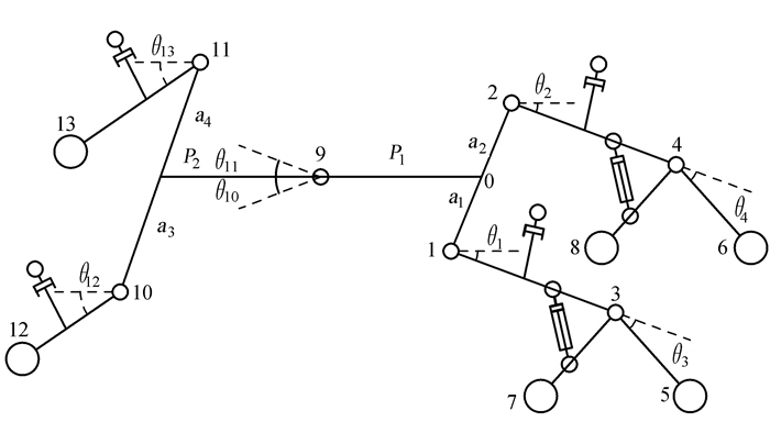
1 主动步态六轮轮腿底盘简介及运动学建模 1.1 主动步态变幅轮腿底盘结构简介主动步态变幅轮腿底盘结构主要由前、后车架及左前、左后、右前、右后共四轮腿系统组成。目前林用底盘越障运动有主动步态和被动步态两种,主动步态是指底盘轮腿在越障运动前先主动抬升轮腿后完成跨越越障动作,被动步态则无此提前预测抬升动作,而是被动适应障碍物高度。同时轮腿采用变幅控制,即轮腿主动抬升是根据障碍物高度变化的;等幅控制则是无论障碍物高度多少,始终抬升相同高度,相比轮腿变幅控制可使越障运动更加精确和节能,提高底盘地形适应性能。底盘结构(图 1)为左右对称式布置,数值a1=a2,a3=a4;θ1=θ2,θ3=θ4,θ10=θ11,θ12=θ13。

|
注:1和2分别为右、左前轮腿关节铰接点,3和4分别为右、左“人”字形轮腿铰接点,5和6分别为右、左“人”字形轮腿前轮轮心,7和8分别为右、左“人”字形轮腿后轮轮心,9为前后车架铰接点,10和11分别为右、左后轮腿铰接点,12和13分别为右、左后轮轮心;a1为右前轮腿铰接点至前车架中心线距离,a3为右后轮腿铰接点至后车架中心线距离;θ1为右前轮腿关节位姿角,θ3为右“人”字形轮腿关节位姿角,θ10为右转向角,θ12为右后轮腿关节位姿角;P1为前后车架铰接点至前车架距离,P2为前后车架铰接点至后车架距离。 Note:1 and 2 are right and left front wheel joint articulation points respectively, 3 and 4 are right and left "人" shaped wheel leg hinge points respectively, 5 and 6 are right and left "人" shaped wheel leg front wheel centers respectively, 7 and 8 are right and left"人" shaped wheel leg rear wheel centers respectively, 9 is front and rear frame hinge points, 10 and 11 are right and left rear wheel leg hinge points respectively, 12 and 13 are right and left rear wheel centers respectively; a1 is the line distance from the right front wheel leg hinge point to the front frame center, a3 is the line distance from the right rear leg hinge point to the rear frame center; θ1 is the position angle of the right front wheel joint, θ3 is the position angle of the right "人" shaped wheel-leg joint, θ10 is right steering angle, θ12 is the position angle of the right rear wheel joint; P1 is the distance from the front and rear frame hinge point to the front frame, P2 is the distance from the front and rear frame hinge point to the rear frame. 图 1 六轮变幅轮腿底盘结构示意图 Fig. 1 The schematic diagram of the six-wheeled leg-luffing articulated vehicle chassis |
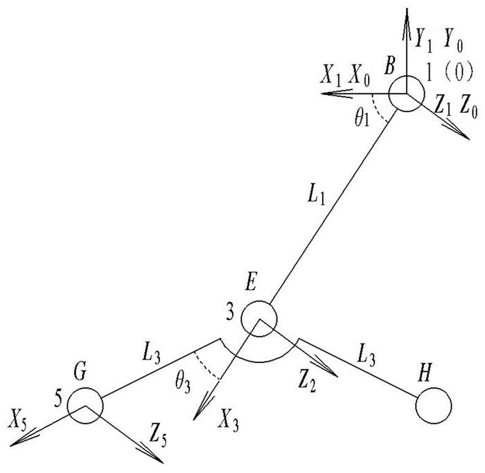
底盘轮腿微分运动可建立轮腿各关节变量的微小变化与轮腿越障高度之间的微分关系,即各关节平移及旋转误差与轮腿轮心的运动偏差的微分关系[13],研究轮腿在越障过程中各关节误差导致的越障高度数值偏差这一问题,即底盘前轮腿关节1、3处关节误差引起的越障高度变化(如图 1)。由于底盘四轮腿分析方法相同,以右前轮腿为例运用D-H参数法建立运动学模型[13](图 2),得到各关节转换参数(表 1)。其中已知θ1为28.1°~61.3°,θ3的取值范围为37.8°~51.8°,L1=467 mm,L3=301 mm。

|
注:X0为基坐标x轴,Y0为基坐标y轴,Z0为基坐标z轴,X1为关节1坐标系x轴,Y1为关节1坐标系y轴,Z1为关节1坐标系z轴,X3为关节3坐标系x轴,Z3为关节3坐标系z轴,X5为关节5坐标系x轴,Z5为关节5坐标系z轴,0为基坐标原点,3为关节3坐标系原点,5为关节5坐标系原点;θ1为绕Z0轴的旋转角,θ3为绕Z1轴的旋转角;L1为沿X2轴平移距离,L3为沿X3轴平移距离;B为关节1,E为关节3;G为“人”字形轮前轮心5,H为“人”字形轮后轮心。 Note:X0 is the x axis of the base coordinate, Y0 is the y axis of the base coordinate, Z0 is the z axis of the base coordinate, X1 is the x axis of the joint 1 coordinate system, Y1 is the y axis of the joint 1 coordinate system, Z1 is the z axis of the joint 1 coordinate system, X3 is the x axis of the joint 3 coordinate system, Y3 is the y axis of the joint 3 coordinate system, Z3 is the z axis of the joint 3 coordinate system, X5 is the x axis of the joint 5 coordinate system, Y5 is the y axis of the joint 5 coordinate system, Z5 is the z axis of the joint 5 coordinate system. 0 is the the origin of the base coordinate, 3 is the origin of the joint 3 coordinate system, 5 is the origin of the joint 5 coordinate system; θ1 is the rotation angle around the Z0 axis, θ3 is the rotation angle around the Z1 axis; L1 is the translation distance along the X2 axis, L3 is the translation distance along the X3 axis; B is joint 1, E is joint 3; G is the front wheel center 5 of the "人" shaped wheel, H is the rear wheel center 5 of the "人" shaped wheel. 图 2 前轮腿运动学坐标系 Fig. 2 The coordinate system of the front wheel-legged kinematics |
| 连杆Link | θ/(°) | d/mm | a/mm | α/(°) |
| 1 | 0 | 0 | 0 | 0 |
| 3 | θ1 | 0 | L1 | 0 |
| 5 | θ3 | 0 | L3 | 0 |
| 注:θ为两连杆夹角,d为两连杆距离,a为连杆长度,α为连杆扭角。Note: θ is the angle between the two connecting rods, d is the distance between the two connecting rods, a is the length of the connecting rod, α is the twist angle of the connecting rod. | ||||
Denavit-Hartenberg参数法(D-H参数法)是表示机器人和对机器人运动进行建模的标准方法,是由Denavit和Hartenberg在1955年提出的一种可用于任何机器人构型的通用方法,可在机器人的每个连杆上都固定一个坐标系,用4×4的齐次变换矩阵来描述相邻两连杆的空间关系。通过依次变换可最终推导出末端执行器相对于基坐标系的位姿,从而建立机器人的运动学方程。根据D-H参数法[14]及轮腿运动学模型即可分别得到底盘四个轮腿运动学方程。以右前轮腿为例,可得轮心5相对基坐标0的运动学方程[7]:
| $ {P_y} = - \left[ {{L_3}\sin \left( {{\theta _1} - {\theta _3}} \right) + {L_1}\sin {\theta _1}} \right] $ | (1) |
由轮腿运动学模型(图 2)分析可知,底盘前轮腿各关节均为回转关节,当轮腿运动时关节平移变量不变化,而关节回转变量会变化。它既可以用给定的当前坐标系描述,也可以用基础坐标系描述[15],轮腿轮心当前坐标系为{5},基础坐标系为{0},经过微分运动后变为M05+dM05,由于轮心坐标系{5}微分运动是相对于基础坐标系{0}进行的,该微分变换矩阵包含了微分平移和微分旋转两个变换。由平移误差及旋转误差共同作用导致的右前轮腿轮心相对基坐标系的偏差d0M5为:
| $ {d^0}{M_5} = \left[ {\begin{array}{*{20}{c}} {\left( {{s_1}{c_3} - {c_1}{c_3}} \right)z}&{ - \left( {{s_1}{s_3} + {c_1}{c_3}} \right)z}&y&{z\left( {{L_3}{c_3}{s_1} - {L_3}{s_3}{c_1} + {L_1}{s_1}} \right) + {a_1}y + \mu }\\ {\left( {{c_1}{c_3} + {s_1}{s_3}} \right)z}&{\left( { - {c_1}{c_3} + {s_1}{c_3}} \right)z}&{ - x}&{z\left( {{L_3}{c_3}{s_1} + {L_3}{s_3}{s_1} + {L_1}{c_1}} \right) - {a_1}x + v}\\ { - \left( {{c_1}{c_3} + {s_1}{s_3}} \right)y + \left( {{s_1}{c_3} + {c_1}{c_3}} \right)x}&{\left( {{c_1}{c_3} - {s_1}{c_3}} \right)y + \left( {{s_1}{s_3} + {c_1}{c_3}} \right)x}&0&{ - y\left( {{L_3}{c_3}{c_1} + {L_3}{s_3}{s_1} + {L_1}{c_1}} \right) + \left( { - {L_3}{c_3}{s_1} + {L_3}{s_3}{c_1} - {L_1}{s_1}} \right)x + w}\\ 0&0&0&0 \end{array}} \right] $ | (2) |
据底盘设计参数(图 2),μ、v、w为各关节在x轴、y轴、z轴方向的平移偏差,x、y、z分别为各关节在x轴、y轴、z轴方向的转角偏差。由于只研究前、后轮腿在xoy平面内沿着y轴方向的位移,ΔPx、ΔPy、ΔPz分别为轮心5在基坐标系内沿x轴、y轴、z轴产生的对应位移误差偏移量。对于如图 2前轮腿D-H运动学模型中轮腿各关节均绕基坐标系的z轴方向转动,均为转动关节。因此,w=x=y=μ=v=0, 而各关节绕z轴的旋转偏差z不为零。z的含义是各关节沿z轴旋转误差的和,单位为弧度。可得各关节偏差共同导致的轮心处在基坐标系x轴、y轴、z轴上的误差偏移量:
| $ \left\{ {\begin{array}{*{20}{l}} {\mathit{\Delta }{P_x} = z\left( {{L_3}{c_3}{s_1} - {L_3}{s_3}{c_1} + {L_1}{s_1}} \right) + {a_1}y + \mu }\\ {\mathit{\Delta }{P_y} = z\left( {{L_3}{c_3}{c_1} + {L_3}{s_3}{s_1} + {L_1}{c_1}} \right) - {a_1}x + v}\\ {\mathit{\Delta }{P_z} = - y\left( {{L_3}{c_3}{c_1} + {L_3}{s_3}{s_1} + {L_1}{c_1}} \right) + \left( { - {L_3}{c_3}{s_1} + {L_3}{s_3}{c_1} - {L_1}{s_1}} \right)x + w} \end{array}} \right. $ | (3) |
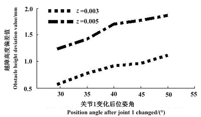
由ΔPy=z(L3c3c1+L3s3s1+L1c1)-a1x+v可知,影响前轮腿越障高度偏差的主要是参数z即各关节绕z轴的旋转误差。结合实际算例、底盘设计参数(图 2)及公式(1)、(2),分别取z=0.003及z=0.005时,得到越障高度偏差值与对应位姿角误差值对应关系曲线(图 3)。由图 3可知, 旋转误差会引起前轮腿位姿角的变化,从而引起的越障高度偏差值也随之变化,且旋转误差越大,其引起的对应越障高度误差值越大。为进一步定量分析底盘前轮腿各关节误差对关节位姿角的影响,对轮腿越障高度Py分别取100~300 mm中5组数值,则对应位姿角θ1分别可得28.81°~50.80°的5组数值;当Py=130 mm、θ3=45°,z=0.01时[16-18], 可得误差后的Py′=Py+ΔPy=-143.04 mm。越障误差为13.04 mm,得到θ1′=-28.98°。因此,θ1由于旋转误差z有Δθ1=θ1′-θ1=0.57°变化。同理取θ3=0.45°时,各参数对应变化值如(表 2)。

|
图 3 不同旋转误差下的越障高度偏差值 Fig. 3 Obstacle height deviation values under different rotation deviation |
| Py/mm | Py′/mm | ΔPy /mm | θ1/(°) | θ1′/(°) | Δθ1/(°) |
| -100 | -112.68 | -12.68 | -28.81 | -28.28 | 0.53 |
| -130 | -143.04 | -13.04 | -29.54 | -28.98 | 0.56 |
| -150 | -163.51 | -13.51 | -32.02 | -31.45 | 0.57 |
| -180 | -187.54 | -7.54 | -42.29 | -41.71 | 0.58 |
| -300 | -305.02 | -5.02 | -50.80 | -50.24 | 0.56 |
| 注:Py为理论越障高度,ΔPy为越障高度偏差值,Py′为实际越障高度;θ1前轮腿关节1位姿角,θ1′为实际关节位姿角,Δθ1为关节位姿角变化值。Note: Py is the theoretical obstacle height, ΔPy is the obstacle height deviation, Py′ is the actual obstacle height;θ1 is the front wheel-leg joint 1 position angle, θ1′ is the actual joint position angle, Δθ1 is the change value of the joint position angle. | |||||
同理,轮腿越障高度Py分别取100~300 mm中选取5组数值,设定z取0.01;θ1=30°时,得位姿角θ3及相应数据值(表 3)。关节1、3处的旋转误差均会影响轮腿越障高度偏差数值,越障高度偏差值是由二者共同作用引起的。由表 2、表 3可知:当越障高度为100~150 mm时,关节1、3旋转误差引起的偏差值分别为12.68~13.51 mm和6.69~6.94 mm;当越障高度为150~300 mm时,关节1、3旋转误差引起的偏差值分别为7.54~5.02 mm和8.01~12.91 mm。说明越障高度小于和大于150 mm时关节1和3旋转误差分别起主要作用。
| Py/mm | Py′/mm | ΔPy /mm | θ3/(°) | θ3′/(°) | Δθ3/(°) |
| -100 | -93.04 | -6.96 | 46.73 | 48.12 | 1.39 |
| -130 | -123.13 | -6.87 | 46.11 | 47.51 | 1.40 |
| -150 | -143.06 | -6.94 | 44.11 | 45.49 | 1.38 |
| -180 | -171.99 | -8.01 | 40.24 | 41.60 | 1.36 |
| -300 | -287.09 | -12.91 | 38.83 | 40.23 | 1.40 |
| 注:Py为理论越障高度,ΔPy为越障高度偏差值,Py′为实际越障高度;θ3为前轮腿关节3位姿角,θ3′为实际关节位姿角,Δθ3为关节位姿角变化值。Note: Py is the theoretical obstacle height, ΔPy is the obstacle height deviation, Py′ is the actual obstacle height;θ3 is the front wheel-leg joint 3 position angle, θ3′ is the actual joint position angle, Δθ3 is the change value of the joint position angle. | |||||
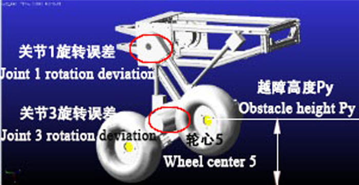
机械系统动力学自动分析(automatic dynamic analysis of mechanical systems, ADAMS)软件是美国MDI公司(Mechanical Dynamics Inc.)开发的虚拟样机分析软件。ADAMS使用交互式图形环境和零件库、约束库、力库等能够创建完全参数化的机械系统动力学模型。是以多体系统动力学理论为基础开发出的机械系统仿真分析软件[19]。借助该虚拟平台可在计算机上建立三维可视化模型,模拟在现实环境下系统的运动和动力特性。该软件主要有View、Solver和Postprocessor三大基本模块[20],本研究轮腿越障的动力学仿真是基于主模块View完成的。仿真方法:取与理论分析相同越障高度数值,得到对应关节位姿角θ1与θ3,并在模型中按安装角1%的比例调整关节1、关节3位姿精度[21]得到θ1′与θ3′,实现轮腿越障仿真运动如图 4所示,同时测得对应的Py′, 得到各对应越障高度偏差和关节旋转误差与越障高度偏差的影响关系。对应各参数数值如表 4和表 5。

|
图 4 前轮腿旋转误差引起越障高度变化仿真过程 Fig. 4 The simulation process of the obstacle height change caused by the front wheel leg rotation error |
| Py/mm | Py′/mm | ΔPy /mm | θ1/(°) | θ1′/(°) | Δθ1/(°) |
| -100 | -118.63 | -18.63 | -28.81 | -28.40 | 0.41 |
| -130 | -142.19 | -12.19 | -29.54 | -28.96 | 0.58 |
| -150 | -159.85 | -9.85 | -32.02 | -31.51 | 0.51 |
| -180 | -183.16 | -3.16 | -42.29 | -41.74 | 0.55 |
| -300 | -302.31 | -2.31 | -50.08 | -49.59 | 0.49 |
| 注:Py为理论越障高度,ΔPy为越障高度偏差值,Py′为实际越障高度;θ1前轮腿关节1位姿角,θ1′为实际关节位姿角,Δθ1为关节位姿角变化值。Note: Py is the theoretical obstacle height, ΔPy is the obstacle height deviation, Py′ is the actual obstacle height;θ1 is the front wheel-leg joint 1 position angle, θ1′ is the actual joint position angle, Δθ1 is the change value of the joint position angle. | |||||
| Py/mm | Py′/mm | ΔPy /mm | θ3/(°) | θ3′/(°) | Δθ3/(°) |
| -100 | -94.99 | -5.01 | 46.73 | 48.03 | 1.30 |
| -130 | -125.50 | -4.95 | 46.11 | 47.09 | 0.98 |
| -150 | -142.59 | -7.41 | 44.11 | 45.40 | 1.29 |
| -180 | -164.70 | -15.30 | 40.24 | 41.62 | 1.38 |
| -300 | -282.89 | -17.11 | 38.83 | 40.22 | 1.39 |
| 注:Py为理论越障高度,ΔPy为越障高度偏差值,Py′为实际越障高度;θ3为前轮腿关节3位姿角,θ3′为实际关节位姿角,Δθ3为关节位姿角变化值。Note: Py is the theoretical obstacle height, ΔPy is the obstacle height deviation, Py′ is the actual obstacle height;θ3 is the front wheel-leg joint 3 position angle, θ3′ is the actual joint position angle, Δθ3 is the change value of the joint position angle. | |||||
测试方法:采用经典PID控制理论在Codsys软件编程环境下实现对ESPC工业控制器的控制[22],建立了完整的控制系统。使用角度、位移传感器实现了对相应驱动器分别对控制缸程序控制,实现按要求对行程的精确调整;同时得到相应关节角度、位移变化信号,实现对旋转误差的设置与测试。测试过程:(控制缸型号为L型直线电机E05 10 mm·s-1)通过设定前轮腿关节1、关节3处的位姿角度,如图 5,采用对应高度位置定位标识,使用直尺、转角测量仪、游标卡尺进行转角、高度微小变化测量,并多次测量取平均值对应得到多组越障高度数值Py′(图 5), 得到符合条件其中5组数值(表 6、表 7)。

|
图 5 前轮腿旋转误差引起越障高度变化实测过程 Fig. 5 The measurement process of the obstacle height change caused by the front wheel leg rotation deviation |
| Py/mm | Py′/mm | ΔPy /mm | θ1/(°) | θ1′/(°) | Δθ1/(°) |
| -100 | -107.32 | -7.32 | -28.81 | -28.35 | 0.46 |
| -130 | -140.64 | -10.64 | -29.54 | -28.99 | 0.55 |
| -150 | -161.23 | -11.23 | -32.02 | -31.47 | 0.55 |
| -180 | -185.39 | -5.39 | -42.29 | -41.08 | 0.49 |
| -300 | -305.68 | -5.68 | -50.08 | -49.45 | 0.63 |
| 注:Py为理论越障高度,ΔPy为越障高度偏差值,Py′为实际越障高度;θ1为前轮腿关节3位姿角,θ1′为实际关节位姿角,Δθ1为关节位姿角变化值。Note: Py is the theoretical obstacle height, ΔPy is the obstacle height deviation, Py′ is the actual obstacle height;θ1 is the front wheel-leg joint 3 position angle, θ1′ is the actual joint position angle, Δθ1 is the change value of the joint position angle. | |||||
| Py/mm | Py′/mm | ΔPy /mm | θ3/(°) | θ3′/(°) | Δθ3/(°) |
| -100 | -92.99 | -7.01 | 46.73 | 47.58 | 0.85 |
| -130 | -122.47 | -7.53 | 46.11 | 47.43 | 1.32 |
| -150 | -140.62 | -9.38 | 44.11 | 45.70 | 1.59 |
| -180 | -166.79 | -15.30 | 40.34 | 41.85 | 1.51 |
| -300 | -284.04 | -17.11 | 38.83 | 40.38 | 1.55 |
| 注:Py为理论越障高度,ΔPy为越障高度偏差值,Py′为实际越障高度;θ3为前轮腿关节3位姿角,θ3′为实际关节位姿角,Δθ3为关节位姿角变化值。Note: Py is the theoretical obstacle height, ΔPy is the obstacle height deviation, Py′ is the actual obstacle height;θ3 is the front wheel-leg joint 3 position angle, θ3′ is the actual joint position angle, Δθ3 is the change value of the joint position angle. | |||||
将表 4~表 7仿真数据、实测数据与前轮腿理论数值比较分析后可知:受驱动电机与联轴器联接、驱动轴与轴承安装精度、安装位置误差、传动误差等运动误差因素的影响,该轮腿关节在旋转方向会产生旋转误差,使得前、后轮腿对应位姿角的变化受到了影响,从而引起越障高产生偏差。当旋转误差z取0.01时,位姿角θ1平均各变化了0.56°、0.51°、0.54°左右;位姿角θ3平均各变化了1.39°、1.27°、1.36°左右。仿真、实测数据与理论数据切合度达96.4%、98.1%,说明底盘各关节的旋转误差会影响位姿角的变化,导致轮腿越障高度的偏差。后轮腿研究方法相同。
3 讨论与结论本研究基于六轮摆臂轮腿底盘构型,研究轮腿关节误差与越障高度之间关系。运用经典D-H参数法建立运动学模型,通过分析相对底盘运动学模型基坐标的轮腿各关节的微分运动,得到底盘轮腿各关节旋转误差与轮腿越障高度关系方程,且越障高度小于和大于150 mm时,位姿角θ1和θ3对应旋转误差分别起主要作用。误差值越大,对应越障高度偏差值越大,实例中实测最大越障值与理论值偏差可达15.96 mm(表 7)。本研究可为底盘减小装配、运动误差、误差补偿、实现轮腿越障运动精确控制提供理论依据,为林用装备底盘越障过程控制策略的制定,满足林用底盘的生产需求,实现底盘越障运动精确控制及提高底盘轮腿越障效率提供参考依据。
| [1] |
赵可, 刘晋浩, 黄青青, 等. 林业并联式铰接底盘优化设计与越障性能仿真分析[J]. 北京林业大学学报, 2018, 40(10): 131-140. |
| [2] |
杨春梅, 刘千军, 李耀祥, 等. 小型履带式采伐机转向理论分析与计算[J]. 森林与环境学报, 2016, 36(1): 111-116. |
| [3] |
徐坤, 郑羿, 丁希仑. 六轮腿式机器人结构设计与运动模式分析[J]. 北京航空航天大学学报, 2016, 42(1): 59-71. |
| [4] |
高英丽, 吴新跃, 吴镇炜. 六轮腿复合型移动机器人越障分析及机构设计[J]. 机械设计与制造, 2013(6): 171-173. DOI:10.3969/j.issn.1001-3997.2013.06.053 |
| [5] |
HAN D T, LIU J H, KAN J M, et al. Analysis of a kinematic model for a forestry six-wheeled luffing articulated vehicle chassis[J]. The Open Mechanical Engineering Journal, 2015, 9: 670-677. DOI:10.2174/1874155X01509010670 |
| [6] |
MOORE R E. Interval analysis[M]. Englewood Clifs, NJ: Prentice Hall, 1966: 26-132.
|
| [7] |
戴厚德, 曾现萍, 游鸿修, 等. 基于光学运动跟踪系统的机器人末端位姿测量与误差补偿[J]. 机器人, 2019, 41(2): 206-215. |
| [8] |
张海南.轮腿机器人运动学与越障分析[D].天津: 河北工业大学, 2014. http://cdmd.cnki.com.cn/Article/CDMD-10080-1015031694.htm
|
| [9] |
周新年, 赖阿红, 周成军, 等. 山地森林生态采运研究进展[J]. 森林与环境学报, 2015, 35(2): 185-192. |
| [10] |
邸向辉, 鲍震宇, 侯捷建, 等. 小兴安岭天然次生林伐区伐根高度统计分析[J]. 森林工程, 2013, 29(6): 1-3. DOI:10.3969/j.issn.1001-005X.2013.06.001 |
| [11] |
洪长福, 薛瑞山, 韩金发. 巨尾桉萌芽更新最佳伐根高度的确定[J]. 森林工程, 2003, 19(1): 11-12, 4. DOI:10.3969/j.issn.1001-005X.2003.01.006 |
| [12] |
肖生灵. 伐根适宜高度的研究[J]. 东北林业大学学报, 1999, 27(4): 42-45. DOI:10.3969/j.issn.1000-5382.1999.04.010 |
| [13] |
蔡自兴. 机器人学[M]. 北京: 清华大学出版社, 2000: 47-61.
|
| [14] |
蔡自兴. 机器人学基础[M]. 北京: 机械工业出版社, 2009: 15-50.
|
| [15] |
宋小康, 谈大龙, 吴镇炜, 等. 全地形轮式移动机器人运动学建模与分析[J]. 机械工程学报, 2008, 44(6): 148-154. DOI:10.3321/j.issn:0577-6686.2008.06.023 |
| [16] |
张晓瑾.串联机器人位姿精度分析与建模[D].沈阳: 东北大学, 2012. http://cdmd.cnki.com.cn/Article/CDMD-10145-1015559660.htm
|
| [17] |
费晓光.串联机器人位姿误差的综合分析[D].沈阳: 东北大学, 2009. http://cdmd.cnki.com.cn/Article/CDMD-10145-1013114960.htm
|
| [18] |
周华飞.机器人自动化制孔中位姿误差的修正与补偿[D].杭州: 浙江大学, 2015. http://cdmd.cnki.com.cn/Article/CDMD-10335-1015630375.htm
|
| [19] |
陈殿生, 黄宇, 王田苗. 轮式腿型机器人的越障分析与仿真[J]. 北京航空航天大学学报, 2009, 35(3): 371-375. |
| [20] |
吉洋.林用履带机器人底盘设计与仿真分析[D].北京: 北京林业大学, 2013. http://cdmd.cnki.com.cn/Article/CDMD-10022-1013213441.htm
|
| [21] |
陈国敏.基于虚拟样机技术的轮腿式移动机器人设计与仿真[D].天津: 河北工业大学, 2011. http://cdmd.cnki.com.cn/Article/CDMD-10080-1012005823.htm
|
| [22] |
江道根.六自由度并联机器人RBF神经网络PID控制研究[D].镇江: 江苏大学, 2010. http://cdmd.cnki.com.cn/Article/CDMD-10299-2010087553.htm
|

 2019, Vol. 39
