2. 哈尔滨工业大学, 黑龙江 哈尔滨 150001
2. Harbin Institute of Technology, Harbin 150001, China
机器人作为典型机电设备具有工作空间大、灵活性高、成本低等优点,且机器人技术是现代制造业中最具前景的技术[1-6]。与单臂机器人相比,双臂机器人在工作效率、工作负载及灵活性方面具备更多的优势,因此备受关注,如双臂协作焊接[7]、双臂协作抓取、倒咖啡[8]等操作[9-11]。双臂协作任务的成功与否很大程度上取决于双臂协作定位精度的高低[12]。但机器人本体的零件加工、关节装配、关节柔性和齿轮间隙等引起的几何误差和非几何误差将降低双臂协作定位精度。解决这个问题的有效方法之一就是对机器人进行运动学标定,在提升单臂机器人精度的基础上建立双臂基坐标系之间的转换关系,进而提升双臂协作定位精度。
对于传统的单臂机器人,机器人的性能主要取决于其定位精度,而定位精度很大程度上会受到几何误差和非几何误差的影响[13-15],因此,机器人运动学标定一般分2步执行。第1步基于参数模型校准机器人运动学模型中的几何参数误差,主要是补偿加工装配所引起的关节转角偏差、连杆扭转误差、连杆长度误差和连杆偏置误差[6, 16];第2步基于非参数模型(如神经网络[13-15, 17-18]、支持向量机[19]、模糊算法[20]等智能方法)补偿关节柔性、关节间隙及齿轮间隙等引起的非几何误差。在基于智能方法补偿间隙等引起的间断型非几何误差时,需要考虑关节的运动方向[13-14]。同时为适应变化工况(如负载变化等因素),智能方法的输入需包含关节位置、关节运动方向和末端负载等因素[21],以使得所建立的非几何误差预测模型适应变化工况并具备泛化能力。基于参数与非参数结合的运动学标定方法简单有效、易于操作,但在以往文献中非参数模型的标定方法只考虑在标定坐标系下提升单臂机器人的绝对定位精度,所建立的非几何误差预测模型只能在标定坐标系下进行精确工作,脱离标定坐标系后所建立的非几何误差预测模型便失效了。
对于双臂机器人系统,需要同时提升单臂机器人的运动学精度和双臂系统的协作定位精度。目前,针对单臂运动学标定的研究较为广泛,但针对双臂或多臂机器人系统运动学标定的研究较少[22-28],多集中于多机器人基坐标系转换矩阵参数的辨识[22-23]及双臂系统几何误差的补偿[24-28],忽略了双臂系统的非几何误差。Maier等[29]使用单目相机对仿人机器人Nao的手臂和腿进行标定[29]。Chen等[30]基于最小化最大误差的方法对AR601M双臂机器人进行标定。Zhao等[28]提出了一种双臂机器人联合标定法,对其中1个机器人的绝对定位精度和双臂协作定位精度进行优化,但该方法复杂且很难同时提升2个机器人的绝对定位精度和双臂机器人的协作定位精度。Mao等[12, 26]提出了针对双臂机器人的鲁棒运动学标定方法,通过最小化最大距离误差保证其鲁棒性,并将极小极大问题转换为二次序列规划(sequential quadratic programming,SQR)问题。在以上双臂协作定位精度提升的文献中,均忽略了非几何误差对双臂协作定位精度的影响,但非几何误差依然影响双臂协作定位精度且在高精准作业任务中不容忽视。因此,如何建立一种运动学标定方案同时减小双臂机器人系统的几何误差与非几何误差是一个亟待解决的问题。
为提升双臂机器人系统的协作定位精度,本文提出了一种基于参数与非参数模型相结合的运动学标定方案,该方案在几何误差标定的基础上考虑了双臂系统中的非几何误差,主要内容如下:
1) 基于MDH方法建立机器人模型及几何误差模型,去除模型中的耦合参数,并基于迭代最小二乘法辨识几何参数误差。
2) 基于反向传播神经网络(BPNN)预测单臂机器人的本体非几何误差,提升单臂机器人定位精度。
3) 在几何误差标定的基础上,基于距离误差与迭代最小二乘法(ILS)辨识双臂基坐标转换的参数,并在双臂系统存在几何与非几何误差情况下建立误差补偿方案,提升双臂协作定位精度。
4) 通过实验验证所提出方法的正确性和有效性,并与其他方法对比以证明所提出方法的优越性。
2 双臂系统运动学建模和误差补偿(Kine- matic modeling and error compensation of dual-arm system)双臂机器人系统如图 1所示,该系统由UR10和UR5机器人组成闭环运动链,可用于协作加工、装配、打磨等任务。由于系统任务由双臂机器人协作执行,因此双臂系统的协作定位精度成为工作质量(加工、装配精度及打磨粗糙度等)高低的决定性因素。在这一节中,首先介绍单臂绝对定位精度、单臂相对定位精度和双臂协作定位精度的定义,然后建立基于参数与非参数相结合的运动学两步标定方案,提升单臂定位精度和双臂协作定位精度。

|
图 1 双臂系统坐标系示意图 Fig.1 Schematic of the dual-arm coordinate systems |
单臂绝对定位精度表示机器人在测量坐标系下实测末端位置
| $ \begin{align} E=\| \mathit{\boldsymbol{P}}_{\rm M} -\mathit{\boldsymbol{P}}_{\rm C} \| \end{align} $ | (1) |
相对定位精度在ISO 9283中的定义表述如下:机械臂从当前位置精确运动到下一指令的能力,即距离精度,可表述为
| $ \begin{align} \Delta d=| d_{\rm M} -d_{\rm C} | \end{align} $ | (2) |
其中
双臂协作定位误差[26]可定义为
| $ \begin{align} \Delta D=| D_{\rm M} -D_{\rm C} | \end{align} $ | (3) |
其中
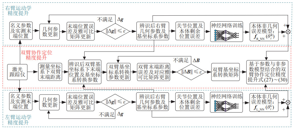
双臂机器人系统常用于执行需要协作配合、高精度、精细操作的任务,双臂机器人标定算法需要同时保证2个机械臂的定位精度和双臂协作定位精度,因此提出了一种基于参数与非参数模型结合的双臂机器人标定方案,该方案的标定流程如图 2所示。第1步,基于参数模型分别标定两机械臂的几何参数,基于非参数模型补偿机器人本体非几何误差;第2步,基于已辨识的几何参数对两臂基坐标变换矩阵的参数进行辨识,并基于单臂本体非几何误差预测模型提升双臂协作定位精度。
|
图 2 双臂系统标定工作流程 Fig.2 Calibration workflow of the dual-arm system |
对于双臂机器人,左机械臂UR10和右机械臂UR5(其名义参数如表 1和表 2所示)的前向运动学模型可表示为
| $ \begin{align} \mathit{\boldsymbol{T}}_{\rm L} &=\mathit{\boldsymbol{T}}_{{\rm L}\_ {0}}^{{\rm L}\_ {\rm M}} \mathit{\boldsymbol{T}}_{{\rm L}\_ {1}}^{{\rm L}\_ {0}} \mathit{\boldsymbol{T}}_{{\rm L}\_ {2}}^{{\rm L}\_ {1}} \mathit{\boldsymbol{T}}_{{\rm L}\_ {3}}^{{\rm L}\_ {2}} \mathit{\boldsymbol{T}}_{{\rm L}\_ {4}}^{{\rm L}\_ {3}} \mathit{\boldsymbol{T}}_{{\rm L}\_ {5}}^{{\rm L}\_ {4}} \mathit{\boldsymbol{T}}_{{\rm L}\_ {\text{flange}}}^{{\rm L}\_ {5}} \mathit{\boldsymbol{T}}_{{\rm L}\_ {\text{tool}}}^{{\rm L}\_ {\text{flange}}} \\ & =\mathit{\boldsymbol{f}}\left(\mathit{\boldsymbol{\theta}}_{\rm L}, \mathit{\boldsymbol{g}}_{\rm L}\right) \end{align} $ | (4) |
| $ \begin{align} \mathit{\boldsymbol{T}}_{\rm R} & =\mathit{\boldsymbol{T}}_{{\rm R}\_{0}}^{{\rm R}\_{\rm M}} \mathit{\boldsymbol{T}}_{{\rm R}\_{1}}^{{\rm R}\_{0}} \mathit{\boldsymbol{T}}_{{\rm R}\_{2}}^{{\rm R}\_{1}} \mathit{\boldsymbol{T}}_{{\rm R}\_{3}}^{{\rm R}\_{2}} \mathit{\boldsymbol{T}}_{{\rm R}\_{4}}^{{\rm R}\_{3}} \mathit{\boldsymbol{T}}_{{\rm R}\_{5}}^{{\rm R}\_{4}} \mathit{\boldsymbol{T}}_{{\rm R}\_{\text{flange}}}^{{\rm R}\_{5}} \mathit{\boldsymbol{T}}_{{\rm R}\_{\text{tool}}}^{{\rm R}\_{\text{flange}}} \\ & =\mathit{\boldsymbol{f}} \left(\mathit{\boldsymbol{\theta}}_{\rm R}, \mathit{\boldsymbol{g}}_{\rm R}\right) \end{align} $ | (5) |
|
|
表 1 UR10机器人名义参数 Tab. 1 Nominal parameters of the UR10 robot |
|
|
表 2 UR5机器人名义参数 Tab. 2 Nominal parameters of the UR5 robot |
其中,
| $ \begin{align} \mathit{\boldsymbol{T}}_{j\_0}^{j{\rm \_M}} =\, &\text{trans}(x_{j\_0}, y_{j\_0})\text{rot}_x (\alpha_{j\_0}) \text{rot}_y (\beta_{j\_0}) \\ & \text{trans}(z_{j\_0})\text{rot}_z(\theta_{j\_0}) \end{align} $ | (6) |
其中,trans表示沿当前坐标系坐标轴的平移齐次变换矩阵,rot表示绕当前坐标系坐标轴的旋转齐次变换矩阵。
| $ \begin{align} \mathit{\boldsymbol{T}}_{j\_i+1}^{j\_i} =\text{rot}_z(\theta_{j\_i})\text{trans}(a_{j\_i}, d_{j\_i})\text{rot}_x (\alpha_{j\_i}) \text{rot}_y (\beta_{j\_i}) \end{align} $ | (7) |
其中,
| $ \begin{align} \mathit{\boldsymbol{T}}_{j\_\text{tool}}^{j\_\text{flange}} =\mathit{\boldsymbol{T}}_{j\_\text{SMR}}^{j\_\text{flange}} \mathit{\boldsymbol{T}}_{j\_\text{tool}}^{j\_\text{SMR}} \end{align} $ | (8) |
其中,
| $ \begin{align} \mathit{\boldsymbol{T}}_{j\_\text{SMR}}^{j{\rm \_M}} =\mathit{\boldsymbol{T}}_{j\_0}^{j{\rm \_M}} \mathit{\boldsymbol{T}}_{j\_\text{flange}}^{j \_0} \mathit{\boldsymbol{T}}_{j\_\text{SMR}}^{j\_\text{flange}} \end{align} $ | (9) |
其中,
| $ \begin{align} \mathit{\boldsymbol{T}}_{j\_\text{SMR}}^{j\_\text{flange}} =\text{trans} \left(t_{j\_x}, t_{j\_z}, t_{j\_y}\right) \end{align} $ | (10) |
在辨识过程中,需要同时对
实际应用中,末端执行器实际到达位置与理论模型计算位置不一致,机器人末端位置误差与几何参数误差之间的关系可表示为
| $ \begin{align} \Delta \mathit{\boldsymbol{P}}_{3\times 1} & = \mathit{\boldsymbol{J}} _{3\times 34} \Delta \mathit{\boldsymbol{g}}_{34\times 1} \end{align} $ | (11) |
| $ \begin{align} \Delta \mathit{\boldsymbol{P}}_{3\times 1} & = \mathit{\boldsymbol{J}} _{3\times 34} \left(\Delta \mathit{\boldsymbol{B}}+\Delta \mathit{\boldsymbol{q}}+\Delta \mathit{\boldsymbol{T}}\right) \end{align} $ | (12) |
其中,
| $ \begin{equation} \begin{split} \mathit{\boldsymbol{J}} _{\theta i} & =[\mathit{\boldsymbol{z}}_{i-1} \times \mathit{\boldsymbol{P}}_{i-1, n} ], \; \; \; \mathit{\boldsymbol{J}} _{ di} =[\mathit{\boldsymbol{z}}_{i-1}], \; \; \; \mathit{\boldsymbol{J}} _{ ai} =[\mathit{\boldsymbol{x}}_{i}'] \\ \mathit{\boldsymbol{J}} _{\alpha i} & =[\mathit{\boldsymbol{x}}_{i}' \times \mathit{\boldsymbol{P}}_{i, n}'], \; \; \; \mathit{\boldsymbol{J}} _{yi} =[\mathit{\boldsymbol{y}}_{i}''], \; \; \; \mathit{\boldsymbol{J}} _{\beta i} =[\mathit{\boldsymbol{y}}_{i} \times \mathit{\boldsymbol{P}}_{i, n}] \end{split} \end{equation} $ | (13) |
坐标系
| $ \begin{align} \Delta \mathit{\boldsymbol{P}}_{3\times 1} = \mathit{\boldsymbol{J}} _{3\times 26} \Delta \mathit{\boldsymbol{g}}_{26\times 1} \end{align} $ | (14) |
|
|
表 3 UR10机器人可辨识参数 Tab. 3 Identifiable parameters of the UR10 robot |
使用激光跟踪仪测量
| $ \begin{align} \mathit{\boldsymbol{g}}_{k} =\mathit{\boldsymbol{g}}_{k-1} +\Delta \mathit{\boldsymbol{g}}_{k} \end{align} $ | (15) |
其中,
| $ \begin{align} \Delta \mathit{\boldsymbol{g}}_{k} =( \mathit{\boldsymbol{J}} _{k}^{\rm T}\mathit{\boldsymbol{J}} _{k} )^{-1} \mathit{\boldsymbol{J}} _{k}^{\rm T} \Delta \mathit{\boldsymbol{P}}_{k} \end{align} $ | (16) |
| $ \begin{align} \mathit{\boldsymbol{P}}_{\rm C} =[f_{j} (\mathit{\boldsymbol{\theta}}_{i}) ]_{(1:3, 4)} \end{align} $ | (17) |
其中,
| $ \begin{align} \Delta \mathit{\boldsymbol{P}}_{\rm E} =\mathit{\boldsymbol{P}}_{\rm M} -\mathit{\boldsymbol{P}}_{\rm C} \end{align} $ | (18) |
其中,
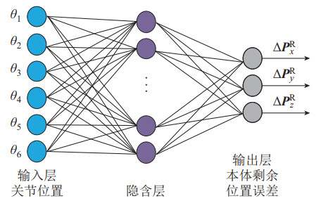
机器人几何误差标定后,剩余位置误差依然受到非几何误差的影响,同时非几何误差会影响双臂系统的协作定位精度。由于BPNN具有较好的非线性逼近能力,且许多学者使用BPNN补偿非几何误差[13-15, 17-18],因此本文基于BPNN补偿机器人的非几何误差。本文神经网络的输入为关节位置,而BPNN输出与文[13-15, 17-18]不同,其输出为机器人本体非几何误差:
| $ \begin{align} \Delta \mathit{\boldsymbol{P}}_{\rm E}^{\rm R} =\left[ \left(\mathit{\boldsymbol{T}}_{0}^{\rm M}\right)^{-1} \left[ \mathit{\boldsymbol{P}}_{\rm M} \; \; 1 \right]^{\rm T}-\left(\mathit{\boldsymbol{T}}_{0}^{\rm M} \right)^{-1} \left[ \mathit{\boldsymbol{P}}_{\rm C} \; \; 1 \right]^{\rm T}\right]_{1:3} \end{align} $ | (19) |
其中,
|
图 3 基于BPNN预测剩余位置误差结构框图 Fig.3 Structural block diagram of residual position error prediction based on BPNN |
|
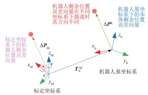
图 4 剩余位置误差在不同坐标系下的描述 Fig.4 Description of residual position error in different frames |
双臂协作任务需要建立双臂间相对位置关系,因此需要辨识双臂机器人基坐标系转换矩阵的参数。在2.3节和2.4节中已经详细介绍了单臂机器人几何与非几何误差补偿方法。本节将通过减小双臂机器人协作距离误差辨识双臂基坐标系转换矩阵的参数。所测量的双臂末端位置分别为
| $ \begin{align} \mathit{\boldsymbol{T}}_{\rm L}^{\rm R} & =\begin{bmatrix} \mathit{\boldsymbol{R}}_{\rm L}^{\rm R} & \mathit{\boldsymbol{b}}_{\rm L}^{\rm R} \\ 0 & 1 \end{bmatrix} \\ &= \begin{bmatrix} c_{\beta_{\rm R}} c_{\theta_{\rm R}} & \begin{array}{c}c_{\theta_{\rm R}} s_{a_{\rm R}} s_{\beta_{\rm R}} -\\[-7pt] c_{a_{\rm R}} s_{\theta_{\rm R}}\end{array} & \begin{array}{c}s_{a_{\rm R}} s_{\theta_{\rm R}} +\\[-7pt] c_{a_{\rm R}} c_{\theta_{\rm R}} s_{\beta_{\rm R}} \end{array}& {x_{\rm R}} \\ c_{\beta_{\rm R}} s_{\theta_{\rm R}} & \begin{array}{c}c_{a_{\rm R}} c_{\theta_{\rm R}} +\\[-7pt] s_{a_{\rm R}} s_{\beta_{\rm R}} s_{\theta_{\rm R}}\end{array} & \begin{array}{c}c_{a_{\rm R}} s_{\beta_{\rm R}} s_{\theta_{\rm R}} -\\[-7pt] c_{\theta_{\rm R} } s_{a_{\rm R}}\end{array} & {y_{\rm R}} \\ -s_{\beta_{\rm R}} & {c_{\beta_{\rm R}} s_{a_{\rm R}}} & {c_{a_{\rm R}} s_{\beta_{\rm R}}} & {z_{\rm R}} \\ 0 & 0 & 0 & 1 \end{bmatrix} \end{align} $ | (20) |
其中,
| $ \begin{align} \mathit{\boldsymbol{P}}_{\rm L}^{\rm R} =\mathit{\boldsymbol{R}}_{\rm L}^{\rm R} \mathit{\boldsymbol{P}}_{\rm L} +{\mathit{\boldsymbol{b}}}_{\rm L}^{\rm R} \end{align} $ | (21) |
双臂末端在右臂基坐标系的位置向量可表述为
| $ \begin{align} \overrightarrow {{P}_{\rm L}^{\rm R} {P}_{\rm R}} =\mathit{\boldsymbol{P}}_{\rm R} - \left(\mathit{\boldsymbol{R}}_{\rm L}^{\rm R} \mathit{\boldsymbol{P}}_{\rm L} +{\mathit{\boldsymbol{b}}}_{\rm L}^{\rm R}\right) \end{align} $ | (22) |
由式(22) 可计算理论模型下双臂末端执行器之间的距离
| $ \begin{align} D_{\rm c} = \left\| \overrightarrow {{P}_{\rm L}^{\rm R} {P}_{\rm R}} \right\| \end{align} $ | (23) |
双臂末端在测量坐标系下的位置为
| $ \begin{align} D_{\rm M} =\left\| \mathit{\boldsymbol{P}}_{\rm L}^{\rm M} -\mathit{\boldsymbol{P}}_{\rm R}^{\rm M} \right\| \end{align} $ | (24) |
基于式(23) 和式(24),可得到理论末端距离与实际末端距离之间的协作定位误差
| $ \begin{align} \Delta D=\sqrt{\left| {D_{\rm M}^{2} -D_{\rm C}^{2}} \right|} \end{align} $ | (25) |
进而得到:
| $ \begin{align} \Delta D^{2}= \left| D_{\rm M}^{2} -\left\|\mathit{\boldsymbol{P}}_{\rm R} -\left(\mathit{\boldsymbol{R}}_{\rm L}^{\rm R} \mathit{\boldsymbol{P}}_{\rm L} +{\mathit{\boldsymbol{b}}}_{\rm L}^{\rm R}\right)\right\|^{2} \right| \end{align} $ | (26) |
对
在实现单臂几何误差标定、单臂本体非几何误差补偿和双臂基坐标系转换矩阵辨识之后提升双臂的协作定位精度,左臂本体基坐标系下末端位置可表示为
| $ \begin{align} \mathit{\boldsymbol{P}}_{\rm L} ={{\mathit{\boldsymbol{f}}}}_{\rm L} \left(\mathit{\boldsymbol{\theta}}_{i}^{\rm L}, {\mathit{\boldsymbol{g}}}^{\rm L}\right)+{{\mathit{\boldsymbol{f}}}}_{\text{L_NN}} \left(\mathit{\boldsymbol{\theta}}_{i}^{\rm L}\right) \end{align} $ | (27) |
其中,
右臂基坐标系下末端位置为
| $ \begin{align} \mathit{\boldsymbol{P}}_{\rm R} ={{\mathit{\boldsymbol{f}}}}_{\rm R} \left(\mathit{\boldsymbol{\theta}}_{i}^{\rm R}, {\mathit{\boldsymbol{g}}}^{\rm R}\right)+{{\mathit{\boldsymbol{f}}}}_{\text{R_NN}} \left(\mathit{\boldsymbol{\theta}}_{i}^{\rm R}\right) \end{align} $ | (28) |
式中右臂参数及函数的定义方式与左臂相同。在单臂几何误差、非几何误差标定及双臂基坐标辨识完成后,在右臂基坐标系下左臂末端位置的
| $ \begin{align} \mathit{\boldsymbol{P}}_{\rm L}^{\rm R} =\mathit{\boldsymbol{R}}_{\rm L}^{\rm R} \left({{\mathit{\boldsymbol{f}}}}_{\rm L} \left(\mathit{\boldsymbol{\theta}}_{i}^{\rm L}, {\mathit{\boldsymbol{g}}}^{\rm L}\right)+{{\mathit{\boldsymbol{f}}}}_{\text{L_NN}} \left(\mathit{\boldsymbol{\theta}}_{i}^{\rm L}\right)\right)+{\mathit{\boldsymbol{b}}}_{\rm L}^{\rm R} \end{align} $ | (29) |
在右臂基坐标系下,双臂末端的位置向量可表示为
| $ \begin{align} \overrightarrow {{P}_{\rm L}^{\rm R} {P}_{\rm R}} ={{\mathit{\boldsymbol{f}}}}_{\rm R} \left(\mathit{\boldsymbol{\theta}}_{i}^{\rm R}, {\mathit{\boldsymbol{g}}}^{\rm R}\right)+{{\mathit{\boldsymbol{f}}}}_{\text{R_NN}} \left(\mathit{\boldsymbol{\theta}}_{i}^{\rm R}\right)-\mathit{\boldsymbol{P}}_{\rm L}^{\rm R} \end{align} $ | (30) |
基于式(30) 可得到经几何和非几何误差补偿后的双臂协作定位误差:
| $ \begin{align} \Delta D= \left| D_{\rm M} - \left\| \overrightarrow {{P}_{\rm L}^{\rm R} {P}_{\rm R}} \right\| \right| \end{align} $ | (31) |
其中,
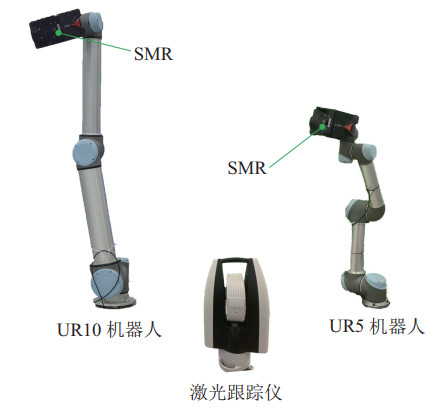
双臂标定实验的系统设置如图 5所示,标定系统由UR10、UR5、Leica AT960激光跟踪仪和SMR反射镜构成。激光跟踪仪的位置精度为
|
图 5 双臂标定系统实验设置 Fig.5 Experimental setup of the dual-arm calibration system |
在激光跟踪仪的最大可测量空间中双臂机器人分别生成400组关节配置并测量末端位置,其中100组关节配置及实测的末端位置用于运动学参数辨识,200组用于本体非几何误差的训练,100组用于单臂机器人末端定位精度与距离误差的验证。
3.2 冗余参数对辨识的影响从辨识时间和辨识后末端位置的精度等方面对冗余辨识模型(式(12))和无冗余辨识模型(式(14))进行了比较。由于UR10机器人与UR5机器人构形相同,在此只进行UR10机器人冗余参数辨识的比较与分析。采用相同的辨识方法和初始参数对几何参数进行辨识。其中
|
|
表 4 冗余模型与无冗余模型辨识性能的比较 Tab. 4 Comparison of identification performance of the redundant model and the non-redundant model |
|
|
表 5 UR10机器人冗余模型辨识结果 Tab. 5 Identification results of the UR10 robot redundant model |
|
|
表 6 UR10机器人无冗余模型辨识结果 Tab. 6 Identification results of the UR10 robot non-redundant model |
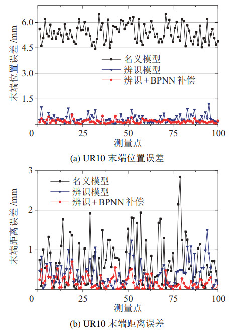
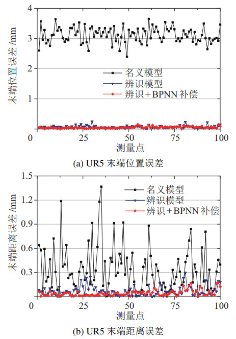
去除冗余参数后,UR10和UR5机器人的运动学参数如表 6和表 7所示,标定后UR10和UR5机器人的位置误差与距离误差分别如图 6、图 7和表 8、表 9所示。基于图 6、图 7与表 8和表 9分析可知,几何标定可以有效减小机器人末端的位置误差及距离误差,但在基于参数模型标定后,机器人的剩余位置误差依然受连杆柔性、关节柔性等引起的非几何误差的影响,使用BPNN对机器人剩余位置误差进行预测,与文[13-15, 17-18]不同,为了提升双臂协作定位精度,本文中神经网络的输出为机器人本体的剩余位置误差式(19),而非标定坐标系下的剩余位置误差。神经网络训练完成后,UR10机器人末端的平均位置误差与距离误差分别减小为0.170 9 mm与0.177 9 mm,UR5机器人末端的平均位置误差与距离误差分别减小为0.050 9 mm和0.042 4 mm。
|
|
表 7 表UR5机器人无冗余模型辨识结果 Tab. 7 Identification results of the UR5 robot non-redundant model |
|
图 6 UR10机器人运动学精度 Fig.6 Kinematic accuracy of the UR10 robot |
|
图 7 UR5机器人运动学精度 Fig.7 Kinematic accuracy of the UR5 robot |
|
|
表 8 UR10机器人运动学误差(单位:mm) Tab. 8 Kinematic errors of the UR10 robot (unit: mm) |
|
|
表 9 UR5机器人运动学误差(单位:mm) Tab. 9 Kinematic errors of the UR5 robot (unit: mm) |
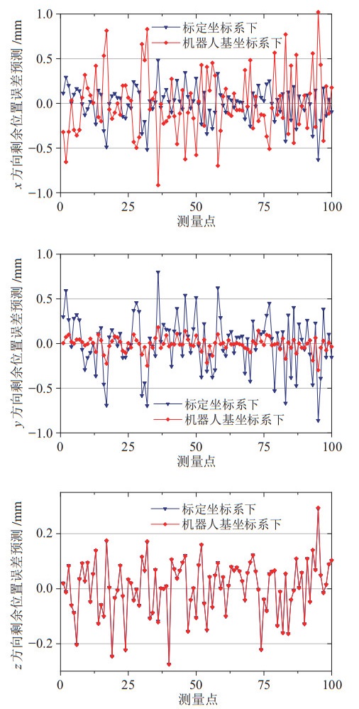
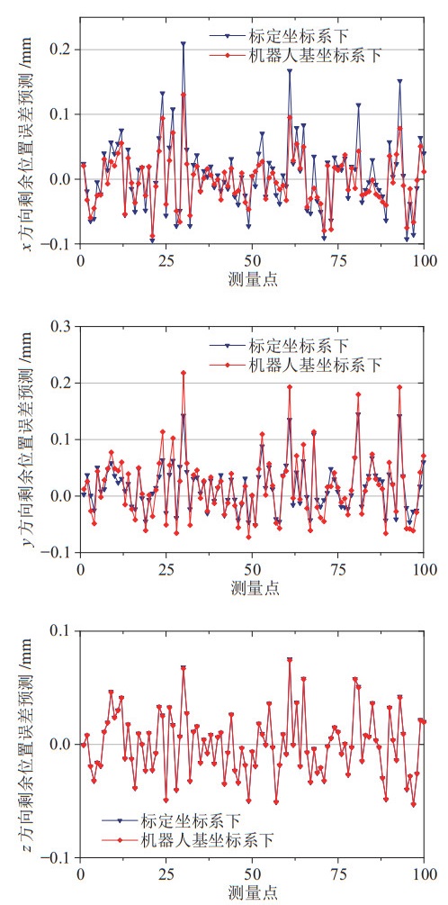
受标定坐标系与机器人基坐标系之间转换矩阵的影响,剩余位置误差在两坐标系下的向量方向不同,UR10与UR5机器人在不同坐标系下的剩余位置误差如图 8和图 9所示。由于测量坐标系与机器人基坐标系的
|
图 8 UR10机器人剩余位置误差在不同坐标系下的描述 Fig.8 Description of residual position error of the UR10 robot in different coordinate systems |
|
图 9 UR5机器人剩余位置误差在不同坐标系下的描述 Fig.9 Description of residual position error of the UR5 robot in different coordinate systems |
在单臂机器人标定完成后,为完成双臂协作任务,需要建立双臂基坐标系转换关系,使用100组数据用于双臂基坐标系转换参数辨识(在单臂400组标定数据中随机均匀取100组数据),100组用于双臂协作定位精度验证,双臂基坐标系的转换参数如表 10所示。基于参数模型的标定方法可有效补偿双臂系统的几何误差,且在双臂运动学标定中最为常用[25-29],因此将所提方法与方法1(基于参数模型的方法)进行比较与分析,以验证基于参数与非参数模型相结合的双臂协作定位精度提升方法的有效性与优越性。同时为证明本体非几何误差补偿的有效性,与方法2(标定坐标系下补偿非几何误差所引起的剩余位置误差的方法)进行了比较。
|
|
表 10 UR10到UR5机器人转换矩阵的参数 Tab. 10 The parameters of transformation matrix from UR10 to UR5 robot |
不同方法下的双臂协作定位误差如图 10和表 11所示,方法1的平均协作定位误差为0.231 9 mm,本文方法的平均协作定位误差为0.167 6 mm,与方法1相比平均协作定位误差降低27.7%,这是因为所提出方法不但考虑了双臂机器人的几何误差,而且基于BPNN建立了机器人的本体非几何误差预测模型,补偿了双臂机器人的非几何误差,进而提升了双臂协作定位精度。方法2的平均协作定位误差为0.466 9 mm,其平均误差高于方法1和本文方法,这说明在标定坐标系下所建立的非几何误差预测模型只能在该坐标系下工作,当坐标系改变时映射关系便失效不成立,故不能提高双臂协作定位精度,甚至降低双臂协作定位精度。
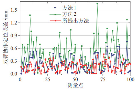
|
图 10 双臂协作定位误差 Fig.10 Dual-arm cooperative positioning error |
|
|
表 11 3种方法的标定结果(单位:mm) Tab. 11 Calibration results of the three methods (unit: mm) |
综上所述,本文提出的基于参数与非参数模型相结合的双臂标定方案,通过减小单臂几何误差和本体非几何误差,并辨识双臂机器人的基坐标系转换参数,有效提升了双臂协作定位精度。由于本文方法考虑了双臂系统的非几何误差,因此其双臂协作定位精度优于方法1和方法2。
4 结论(Conclusion)为提升双臂协作的定位精度,提出了一种基于参数与非参数相结合的运动学标定方案,基于参数模型的方法补偿单臂机器人的几何误差,基于非参数BPNN的方法补偿其本体非几何误差。在提升单臂定位精度的基础上,辨识双臂基坐标系转换矩阵的参数,并建立双臂协作定位误差补偿方案。通过实验验证了所提出方法的正确性和有效性,在补偿几何误差和本体非几何误差后,UR10机器人的平均定位误差为0.170 9 mm,UR5机器人的平均定位误差为0.050 9 mm,双臂协作定位误差为0.167 6 mm,与方法1相比双臂协作定位精度提升27.7%,验证了所提出方法的优越性,因此所提出方法更适用于双臂机器人系统的运动学标定。在未来将致力于研究双臂协作定向精度的提升。
| [1] |
Brunete A, Gambao E, Koskinen J, et al. Hard material small-batch industrial machining robot[J]. Robotics and Computer-Integrated Manufacturing, 2017, 54: 185-199. DOI:10.1016/j.rcim.2017.11.004 |
| [2] |
Guo Y, Dong H, Wang G, et al. Vibration analysis and suppression in robotic boring process[J]. International Journal of Machine Tools and Manufacture, 2016, 101: 102-110. DOI:10.1016/j.ijmachtools.2015.11.011 |
| [3] |
Chen D, Yuan P, Wang T, et al. A compensation method based on error similarity and error correlation to enhance position accuracy of the aviation drilling robot[J]. Measurement Science & Technology, 2018, 29(8). DOI:10.1088/1361-6501/aacd6e |
| [4] |
Slamani M, Gauthier S, Chatelain J F. Comparison of surface roughness quality obtained by high speed CNC trimming and high speed robotic trimming for CFRP laminate[J]. Robotics and Computer-Integrated Manufacturing, 2016, 42: 63-72. DOI:10.1016/j.rcim.2016.05.004 |
| [5] |
Xu X, Zhu D, Wang J, et al. Calibration and accuracy analysis of robotic belt grinding system using the ruby probe and criteria sphere[J]. Robotics and Computer-Integrated Manufacturing, 2018, 51: 189-201. DOI:10.1016/j.rcim.2017.12.006 |
| [6] |
Peng J, Ding Y, Zhang G, et al. An enhanced kinematic model for calibration of robotic machining systems with parallelogram mechanisms[J]. Robotics and Computer-Integrated Manufacturing, 2019, 59: 92-103. DOI:10.1016/j.rcim.2019.03.008 |
| [7] |
段晋军. 多机器人协作焊接中的轨迹规划和位置力协调控制研究[D]. 南京: 东南大学, 2019. Duan J J. Trajectory planning and position force coordination control in multi-robot cooperative welding process[D]. Nanjing: Southeast University, 2019. |
| [8] |
Bäuml B, Schmidt F, Wimböck T, et al. Catching flying balls and preparing coffee: Humanoid Rollin'Justin performs dynamic and sensitive tasks[C]//IEEE International Conference on Robotics and Automation. Piscataway, USA: IEEE, 2011.
|
| [9] |
Li S, He J, Li Y, et al. Distributed recurrent neural networks for cooperative control of manipulators: A game-theoretic perspective[J]. IEEE Transactions on Neural Networks and Learning Systems, 2017, 28(2): 415-426. DOI:10.1109/TNNLS.2016.2516565 |
| [10] |
Hu G, Gans N, Dixon W E. Quaternion-based visual servo control in the presence of camera calibration error[J]. International Journal of Robust and Nonlinear Control, 2010, 20(5): 489-503. DOI:10.1002/rnc.1438 |
| [11] |
Khan M U, Li S, Wang Q, et al. Distributed multirobot formation and tracking control in cluttered environments[J]. ACM Transactions on Autonomous & Adaptive Systems, 2016, 11(2): 12. |
| [12] |
Mao C, Li S, Chen Z, et al. Robust kinematic calibration for improving collaboration accuracy of dual-arm manipulators with experimental validation[J]. Measurement, 2020, 155: 107524-107536. DOI:10.1016/j.measurement.2020.107524 |
| [13] |
Nguyen H N, Zhou J, Kang H J. A calibration method for enhancing robot accuracy through integration of an extended Kalman filter algorithm and an artificial neural network[J]. Neurocomputing, 2015, 151(3): 996-1005. |
| [14] |
Liao S, Zeng Q, Ehmann K F, et al. Parameter identification and nonparametric calibration of the tri-pyramid robot[J]. IEEE/ASME Transactions on Mechatronics, 2020, 25(5): 2309-2317. DOI:10.1109/TMECH.2020.3001021 |
| [15] |
Nguyen H N, Le P N, Kang H J. A new calibration method for enhancing robot position accuracy by combining a robot modelbased identification approach and an artificial neural networkbased error compensation technique[J]. Advances in Mechanical Engineering, 2019, 11(1): 1-11. |
| [16] |
Yu C, Xi J. Simultaneous and on-line calibration of a robotbased inspecting system[J]. Robotics and Computer-Integrated Manufacturing, 2018, 49: 349-360. DOI:10.1016/j.rcim.2017.08.006 |
| [17] |
Le P N, Kang H J. Robot manipulator calibration using a model based identification technique and a neural network with the teaching learning-based optimization[J]. IEEE Access, 2020, 8: 105447-105454. DOI:10.1109/ACCESS.2020.2999927 |
| [18] |
Bai M, Zhang M L, Zhang H, et al. An error compensation method for surgical robot based on RCM mechanism[J]. IEEE Access, 2021, 9: 140747-140758. DOI:10.1109/ACCESS.2021.3117350 |
| [19] |
Bai M, Zhang M L, Zhang H, et al. Calibration method based on models and least-squares support vector regression enhancing robot position accuracy[J]. IEEE Access, 2021, 9: 136060-136070. DOI:10.1109/ACCESS.2021.3115949 |
| [20] |
Bai Y, Zhuang H. On the comparison of model-based and modeless robotic calibration based on a fuzzy interpolation method[J]. International Journal of Advanced Manufacturing Technology, 2007, 31: 1234-1250. |
| [21] |
Hsiao J, Shivam K, Lu I, et al. Positioning accuracy improvement of industrial robots considering configuration and payload effects via a hybrid calibration approach[J]. IEEE Access, 2020, 8: 228992-229005. DOI:10.1109/ACCESS.2020.3045598 |
| [22] |
Wang K J, Chen C H, Lo C Y, et al. Ultrasound calibration for dual-armed surgical navigation system[J]. Journal of Healthcare Engineering, 2022, 22: 1-10. |
| [23] |
Xiong J, Xu C, Ibrahim K, et al. A mechanism-image fusion approach to calibration of an ultrasound-guided dual-arm robotic brachytherapy system[J]. IEEE/ASME Transactions on Mechatronics, 2021, 26(6): 3211-3220. DOI:10.1109/TMECH.2021.3055902 |
| [24] |
Stepanova K, Rozlivek J, Puciow F, et al. Automatic selfcontained calibration of an industrial dual-arm robot with cameras using self-contact, planar constraints, and self-observation[J]. Robotics and Computer-Integrated Manufacturing, 2022, 73: 102250-102270. DOI:10.1016/j.rcim.2021.102250 |
| [25] |
Yang W T, Li K L, Chan K Y, et al. Geometric parameter identification of a dual-arm robot by using closed-chain constraint and optimization technique[J]. Proceedings of the Institution of Mechanical Engineers, Part C: Journal of Mechanical Engineering Science, 2018, 232(7): 1294-1302. DOI:10.1177/0954406217701772 |
| [26] |
祖洪飞, 陈章位, 毛晨涛, 等. 基于极小极大算法的双臂机器人精度提升方法[J]. 振动与冲击, 2022, 41(2): 312-320. Zu H F, Chen Z W, Mao C T, et al. Minimax algorithm for improving the accuracy of dual-arm robots[J]. Journal of Vibration and Shock, 2022, 41(2): 312-320. |
| [27] |
Zhao D, Bi Y, Ke Y. Kinematic modeling and base frame calibration of a dual-machine-based drilling and riveting system for aircraft panel assembly[J]. International Journal of Advanced Manufacturing Technology, 2017, 94: 1873-1884. |
| [28] |
Zhao D, Bi Y, Ke Y. A united kinematic calibration method for a dual-machine system[J]. Assembly Automation, 2017, 38(2): 226-238. |
| [29] |
Maier D, Wrobel S, Bennewitz M. Whole-body self-calibration via graph-optimization and automatic configuration selection[C]//IEEE International Conference on Robotics and Automation. Piscataway, USA: IEEE, 2015: 5662-5668.
|
| [30] |
Chen G, Wang H, Lin Z. Determination of the identifiable parameters in robot calibration based on the POE formula[J]. IEEE Transactions on Robotics, 2014, 30(5): 1066-1077. DOI:10.1109/TRO.2014.2319560 |
| [31] |
Hayati S, Mirmirani M. Improving the absolute positioning accuracy of robot manipulators[J]. Journal of Robotic Systems, 1985, 2(4): 397-413. DOI:10.1002/rob.4620020406 |
| [32] |
Wu L, Ren H. Finding the kinematic base frame of a robot by hand-eye calibration using 3D position data[J]. IEEE Transactions on Automation Science and Engineering, 2017, 14(1): 314-324. DOI:10.1109/TASE.2016.2517674 |
 2023, Vol. 45


