
Horizontal Bearing Performance of the Four-Bucket Jacket Foundation
https://doi.org/10.1007/s11804-024-00450-1
-
Abstract
As an important part of offshore wind turbine support and fixed units, the multibucket jacket foundation bears large loads and a complex marine environment. In this paper, the horizontal bearing characteristics of the four-bucket jacket foundation of offshore wind power in sandy soil are studied. Through model tests and numerical simulations, the influence of bucket foundation sealing properties, load application speed, and loading direction on foundation-bearing capacity are discussed. The results show that the horizontal ultimate bearing capacity of the foundation in the nonsealing condition is decreased by 51.3% compared with the sealing condition; therefore, after the foundation penetration construction is completed, the bucket sealing must be ensured to increase the load-bearing performance of the structure. At a loading speed of 3.25 mm/s, the horizontal ultimate bearing capacity of the foundation is increased by 9.4% over the working condition of 1.85 mm/s. The bearing capacity of the foundation is maximized in the loading direction α =45° and is the smallest when α =0°. That is, the foundation can maximize its load-bearing performance under the condition of single-bucket compression/tension. During the design process, the main load of the structure should be loaded in the 45° direction. The contrast error of the experiment and numerical simulation does not exceed 10%. The research results have important guiding importance for designing and constructing the jacket foundation and can be used as a reference for the stable operation and sustainable development of offshore wind power systems.Article Highlights● The horizontal load-bearing performance of the offshore wind turbine four-bucket jacket foundation is addressed.● The two research methods of model experiments and numerical simulations are found to support and supplement each other.● The bucket top sealing property, loading speed, and loading direction are used as research variables. -
1 Introduction
With increasing concerns about environmental issues and the growing energy demand, offshore wind power has become one of the most important forms of renewable energy in the world today (Zhang et al., 2023a). Compared with traditional fossil energy sources such as coal and oil, offshore wind power has the advantages of being clean, pollution-free, and renewable and is one of the important means of global response to climate change and environmental pollution (Wu et al., 2019). In addition, offshore wind power has the characteristics of wide distribution and an abundant energy source, so it is considered an important component of the future energy supply (Zhang et al., 2022a). However, as offshore wind turbines continue to increase in capacity, their size, weight, and construction costs also increase, annually increasing offshore wind power construction and operation costs (Ding et al., 2022a).
As shown in Figure 1, a supporting structure of offshore wind turbines, the jacket foundation needs to not only bear the weight of the entire unit but also withstand the effects of extremely complex waves, currents, wind, and other factors in the marine environment to ensure that the entire turbine in the sea has stable operation (Lin and Zhang, 2023; Liu and Wei, 2021). However, because of the instability of the marine environment and the complexity of the stress characteristics of the jacket foundation, the horizontal load-bearing performance of the jacket foundation has become an important research direction in the field of offshore wind power (Luo et al., 2023). Understanding the horizontal load-bearing performance of the jacket foundation can help us better understand its stress characteristics and deformation patterns in the offshore environment (Mao et al., 2023). Moreover, an in-depth discussion of the horizontal load-bearing performance of the jacket foundation will help optimize the design and construction plan of the jacket foundation, improve its ability to resist wind, waves, and earthquakes, and ensure sustainable development and safe and stable operation of offshore wind power (Ruan et al., 2022; Zhu et al., 2022).
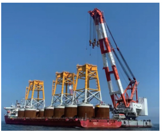 Figure 1 Jacket foundation of an offshore wind turbine
Ding et al. (2023) studied the failure envelope of a three-bucket jacket under composite loading mode, finding that this jacket has a better load-bearing performance with a larger foundation diameter and a smaller bucket height. Le et al. (2021) found through research that the torque limit bearing capacity of the four-bucket jacket foundation increases approximately linearly with increasing bucket skirt height and bucket spacing, and the growth rate is approximately identical. Zhang et al. (2023a) conducted a series of numerical studies on the bearing characteristics of the three-bucket suction jacket foundation in silty and silt soil. The conclusion shows that the horizontal bearing capacity of the three-bucket suction jacket foundation changes regularly under different soil combinations and increases with the thickness of silty sandy soil. Ding et al. (2022b) studied the response mechanism of the air cushion, the basic motion characteristics, and the tension response law of a suspension cable under different initial draft conditions under wave environment loads and clarified the safety performance of the sling cable during the construction process. Most existing research on the bearing characteristics of jacket foundations has been conducted from the perspectives of bucket foundation structure type, soil quality, and environmental loads. Zhang et al. (2023b) studied the bearing performance of the mono-column bucket foundation under cyclic loading through model experiments and numerical simulations. Li et al. (2022) studied the effects of scour range and scour depth on foundation-bearing performance. Wang et al. (2021) studied the improvement of the horizontal load-bearing performance of mono-pile foundations by pile – bucket combined foundations through geotechnical centrifuge tests and numerical simulations. Li et al. (2023) and Xu et al. (2022) found that the loading direction and speed have a greater impact on the bearing characteristics of bucket foundations. However, only a single-model test or numerical model was used for research, and the jacket structure on the upper part of the foundation and the sealing performance of the bucket foundation were neglected, so the analysis was incomplete. In-depth research on the horizontal load-bearing characteristics of offshore wind turbine four-jacket foundations is lacking. To date, no relevant research has been conducted on the impact of the sealing state of the bucket foundation on its load-bearing performance after the foundation is installed. Experimental studies on the effects of loading angle and loading direction on foundation-bearing performance are scarce.
This article addresses the horizontal load-bearing performance of the offshore wind power four-bucket jacket foundation, using a combination of model testing and finite element methods to analyze its stress characteristics under the influence of different bucket foundation sealing properties, different loading speeds, and different loading directions, aiming to guide actual projects to fully use the foundation-bearing performance of offshore wind power jackets.
2 Model introduction
2.1 Physical test models and devices
2.1.1 Test model
The similarity ratio of the test model is 1∶100. The foundation model is made of a steel structure and mainly comprises three parts: bucket foundation, jacket structure, and upper platform. The overall test model is shown in Figure 2, and the main dimensions of each part of the foundation are shown in Table 1.
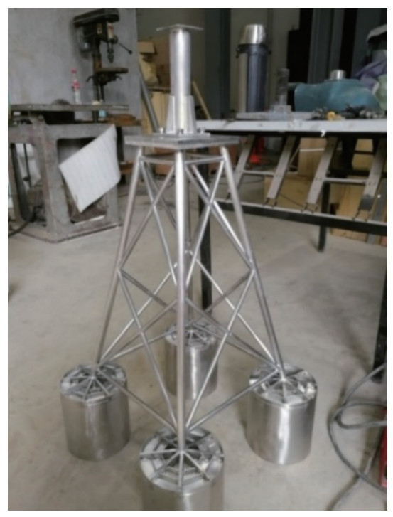 Figure 2 Test model of the four-bucket jacket foundationTable 1 Dimensions of the four-bucket jacket foundation model (mm)
Bucket diameter 159 Bucket space 159 Bucket skirt height 159 Bucket skirt and bucket top thickness 1.5 Overall height of the foundation 915 Three suction holes with a diameter of 16 mm are present on the top cover of each bucket of the basic model. The four-bucket jacket foundation is connected to the suction pump by connecting valves and rubber hoses, as shown in Figure 3(a). A steel mesh and geotextile are installed at the suction hole in the bucket to prevent mud and sand from being pumped up in the hose and causing blockage when the negative pressure sinks, as shown in Figure 3(b). In addition, a movable loading piece is arranged at the loading rod to facilitate the application of horizontal loads in different directions on the four-bucket jacket foundation, as shown in Figure 3(c). The test soil tank model box is 2 m× 2 m×1.5 m. Through the cyclic process of plowing the sand–filling the lower part with water–vibrating–draining– plowing the soil, the sand is layered and watered for maintenance to ensure that the soil reaches a fully saturated state, and a series of geotechnical tests were conducted to measure soil parameters, as shown in Table 2.
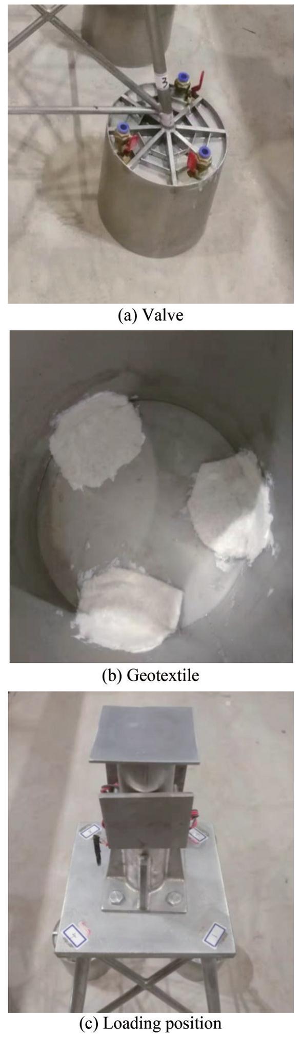 Figure 3 Partial view of the test modelTable 2 Soil parameters
Density ρ (g/cm3) Internal friction angle φ(°) Cohesion c (kPa) Compression modulus Es (MPa) 2.2 34.46 3.27 18 2.1.2 Test device
The test device includes 1) a signal acquisition system, as shown in Figure 4(a); 2) a horizontal push rod to provide power for the four-bucket jacket foundation-bearing capacity test, as shown in Figure 4(b); 3) a horizontal reaction beam, fixed above the soil trench, used to balance the force of the four-bucket jacket foundation acting on the push rod; 4) a pressure sensor, used to measure the horizontal load borne by the four-bucket jacket foundation during the test; 5) a displacement sensor, used to measure the horizontal displacement of the four-bucket jacket foundation; 6) an inclinometer, used to detect the inclination state of the four-bucket jacket foundation during the sinking and leveling process; and 7) a sinking and leveling power system, to provide a driving force for the suction sinking and leveling of the four-bucket jacket foundation. When the suction pump works, it draws out the gas in the bucket to provide suction for the sinking and leveling of the four-bucket jacket foundation. An air pressure storage device—an air–water replacement bucket—is connected between the suction pump and the foundation to provide stable suction for the four-bucket jacket foundation, as shown in Figure 4(c), and a schematic of the test device is shown in Figure 4(d). The main parameters of various test instruments are shown in Table 3:
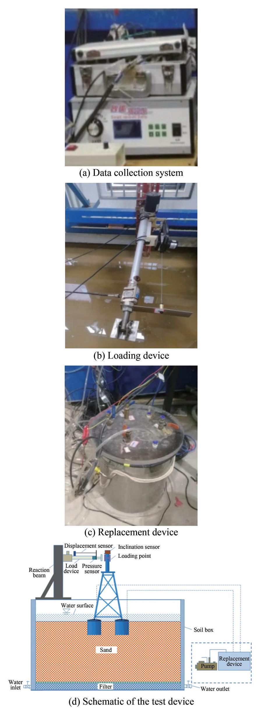 Figure 4 Test equipmentTable 3 Main parameters of the instrument
Name Type Measuring range Accuracy Load device Micromachines 0–2 000 N ─ Pressure sensor Resistance strain gauge 0–30 t 0.5% με Displacement sensor Voltage strain gauge 0–1 m 0.2 mm Inclination sensor Micromachines ±15° ±0.001° The test steps are as follows:
1) Connect the test equipment and test instruments and check whether the instruments and equipment are in normal working condition.
2) Keep the valves at the top of the four buckets open and lift the model vertically into the soil box. After the foundation enters the water and touches the soil, it initially relies on its own weight to penetrate.
3) The four-bucket foundation penetrates to a certain depth under the action of its own weight. When the sinking resistance is greater than the self-weight of the foundation, the foundation no longer penetrates, and the four-bucket foundation's self-weight penetration is considered completed.
4) Take the water surface inside the soil box as the benchmark, pump water and air through the valve on the top of the bucket, and adjust the model inclination angle to less than 0.25°.
5) Then, suction is gradually applied to the bucket so that the foundation can continue to penetrate. During this process, the inclination angle of the structure must be heeded until the foundation sinks into place.
6) Clear the sensor, confirm that the preparation work is completed, turn on the switch of the loading device, load the four-bucket jacket foundation horizontally, and collect data at the same time. When the foundation tilts at a large angle, and it is determined that the limit state has been reached, stop loading.
7) Retract the loading device, open the valve switch on the top of the bucket, increase the pressure in the bucket through the pump, and adjust the size of each valve switch to ensure that the four-bucket foundation can be pushed out smoothly.
2.2 Basic settings of the finite element model
The structural material is stainless steel, and the elastic modulus and Poisson's ratio are 210 GPa and 0.3, respectively. The horizontal load loading height is 73.3 cm above the mud surface. The foundation soil adopts the Mohr – Coulomb calculation constitutive. To fully eliminate the boundary effect, the soil adopts the same 2 m×2 m×1.5 m cube as the physical experiment. The friction coefficient between the four-bucket jacket foundation and the soil is set to 0.3. Set the basic steel structure as the master surface, the soil surface as the slave surface, and the interaction between the bucket and the soil adopts hard contact. In the finite element calculation, the model size and soil parameters are identical to the physical test model. The model is calculated as a whole without considering the jacket installation process. The foundation and soil are meshed into C3D8R units. The loading direction is shown in Figure 5.
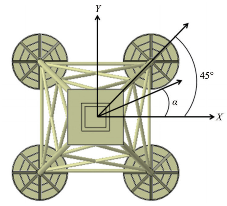 Figure 5 Loading direction definition
2.3 Sensitivity analysis of the mesh
To study the influence of the number of grid cells on the calculation results, four calculation models with different numbers of grid cells were established. The number of grid cells is 55 292, 110 446, 149 395, and 290 904. Taking 0° loading as the standard working condition, the horizontal load-bearing performance of different models was calculated. The displacement load curves and related statistical results of calculation models with different grid cell numbers are shown in Figure 6 and Table 4.
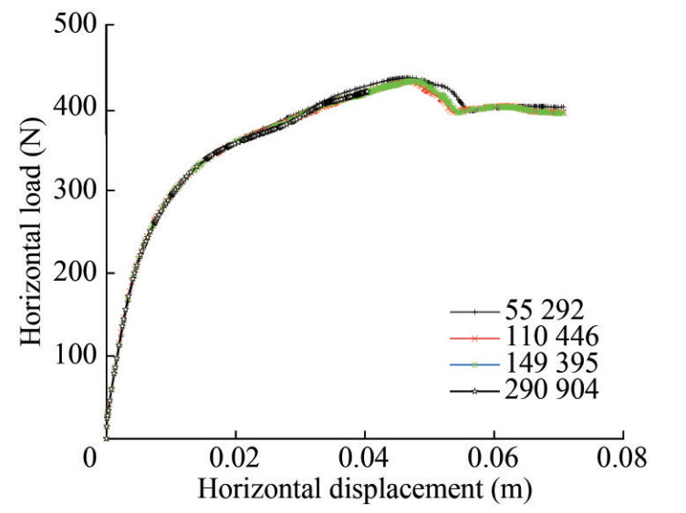 Figure 6 Bearing capacity of different modelsTable 4 Calculation results of different finite element grids
Model Mesh number Ultimate bearing capacity Ultimate displacement Model 1 55 292 435.2 0.046 7 Model 2 110 446 432.1 0.047 4 Model 3 149 395 431.5 0.046 4 Model 4 290 904 419.4 0.040 4 The mesh sensitivity analysis shows that the foundation-bearing performance is not greatly affected by the number of grid cells. To save calculation time, a calculation model with a grid cell number of 55 292 was selected for subsequent research. The finite element calculation model is shown in Figure 7.
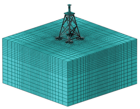 Figure 7 Finite element model
2.4 Test content and working condition settings
To minimize the impact of the side walls of the soil trough on the test results, the model was placed in the center of the soil box. After each group of tests was completed, the soil was cured. During the curing period, water was supplied continuously to ensure that the sand reached a fully saturated state. The pressure sensor was installed at the end of the horizontal load device and used to measure the total resistance of the model under the action of horizontal load. The displacement sensor was fixed on the load device and moved with it to record the force generated by the foundation under the action of horizontal load. The inclinometer was placed on the top of the foundation to monitor the inclination of the foundation in real time during the negative pressure sinking process. The push rod was fixed on the reaction beam to provide power for the four-bucket jacket foundation-bearing capacity test. After the test, a vacuum pump was used to pump air into the bucket, and then the opening and closing of each valve were controlled to ensure that the four-bucket jacket foundation could be ejected smoothly.
In addition to bearing its weight, the offshore wind turbine foundation also bears horizontal loads from different directions. Therefore, the maximum and minimum ultimate bearing capacities of the four-bucket jacket foundation must be studied under the action of horizontal loads. For the four-bucket jacket, the study of the most favorable and unfavorable loading directions of the foundation is crucial. In addition, the test also studied the effects of loading speed and bucket foundation sealing on the foundation-bearing capacity. Because of the symmetry of the basic structure of the four-bucket jacket, to study its loading direction, the direction α between the direction of horizontal load and the positive direction of the X-axis only needs to be analyzed in the range of 0°–45°. The test is mainly divided into three stages: 1) The four-bucket jacket foundation is sunk into place through the structure's weight and suction. 2) The load is applied to the foundation through a loading device, and data are collected. 3) The four-bucket jacket foundation is successfully ejected from the test sand through pump inflation.
The test adopts the loading direction of α = 0°, and the load is tested at speeds of 1.85 and 3.25 mm/s. The results show that these loading speeds are relatively reasonable and provide a reference for the test. The experimental study on the horizontal bearing capacity of the four-bucket jacket foundation is shown in Table 5.
Table 5 Test conditionsWorking conditions Sealing state Loading speed (mm/s) Loading direction (°) 1 Not sealed 1.85 22.5 2 Sealed 1.85 22.5 3 Sealed 1.85 0 4 Sealed 3.25 0 5 Sealed 1.85 45 3 Analysis of test and calculation results
3.1 Results of different sealing states
The sinking of offshore wind power bucket-type foundations is usually suction-induced. After the sinking is in place, if the valve on the top of the bucket is opened, the water inside and outside the bucket will be connected under the action of environmental loads, and the bucket will always be in a pressureless state. This test will study the basic horizontal bearing capacity of the bucket top valve in two states: open and closed.
The test is divided into two groups of test conditions and compared by controlling the opening and closing of the valve on the top of the bucket. The test parameters are shown in Table 5. In working condition 1, all valves on the top of the bucket are opened to connect the water inside and outside the bucket to ensure that the bucket is unpressurized when the four-bucket jacket foundation is loaded. In working condition 2, all valve switches are closed to ensure that the bucket foundation is in a sealed state and the bucket is in a pressurized state under load.
Through the test, it is determined that when the four-bucket jacket foundation is loaded at 22.5°, the load–displacement curves of the bucket top valve are open and closed, as shown in Figure 8. It is seen that when the bucket top valve is closed, the horizontal ultimate bearing capacity of the foundation is 462 N, and the corresponding ultimate horizontal displacement is 0.058 m. When the bucket top valve is open, the horizontal ultimate bearing capacity of the foundation is 225 N, and the corresponding ultimate horizontal displacement is 0.055 m. The horizontal ultimate bearing capacity when the bucket top valve is open is 51.3% lower than when the valve is closed, and the corresponding horizontal ultimate displacement is also reduced. It is seen that the sealing performance of the bucket foundation has a great impact on the foundation's load-bearing capacity. During the test process, if the valve on the top of the test model bucket is not completely closed or there is air leakage in the bucket foundation, a better result will be obtained compared to that of a fully closed valve. The bearing capacity in the state is relatively small.
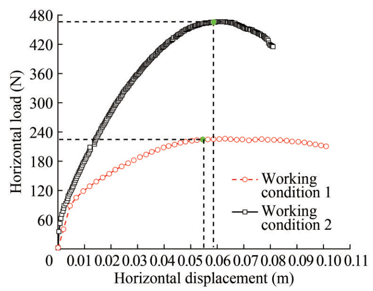 Figure 8 Horizontal load – displacement curve under open/closed conditions of the bucket top valve
3.2 Results of different loading speeds
Static testing is currently one of the most common methods in structural testing. The loading speed in static testing directly affects the accuracy of test results and the test completion time. Therefore, an appropriate loading speed must be chosen. Working conditions 3 and 4 in Table 4 were selected to conduct two sets of experimental studies, and the impact of loading speed on the foundation-bearing capacity was obtained, providing a reference for selecting a reasonable loading speed for the test.
The load–displacement curves under two loading speed conditions were obtained experimentally, as shown in Figure 9. This figure shows that when the loading speed is 1.85 and 3.25 mm/s, the ultimate horizontal bearing capacity of the four-bucket jacket foundation is 425 and 465 N, respectively. Compared with the loading speed of 1.85 mm/s, the bearing capacity increased by 9.4% at 3.25 mm/s, indicating that the basic horizontal ultimate bearing capacity increased with the loading speed. Therefore, a smaller loading speed can obtain more conservative results and is more consistent with the actual stress state of wind turbine units in actual projects. Therefore, the loading speed of the four-bucket jacket foundation in the test was 1.85 mm/s.
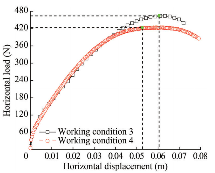 Figure 9 Horizontal load–displacement curves at different loading speeds
3.3 Results of different loading directions
Given the action direction of horizontal load, this test studies the ultimate bearing capacity of the foundation under the three working conditions of α =0°, 22.5°, and 45°, namely, in the test conditions 3, 2, and 5, and different loading directions are obtained by adjusting the position of the loading piece on the loading rod. The foundation position when loading in different directions is shown in Figure 10. When loading in different directions, the four-bucket jacket foundation with pressure in the bucket is loaded at a speed of 1.85 mm/s. This group of tests was conducted to compare the results of model tests and numerical simulation calculations.
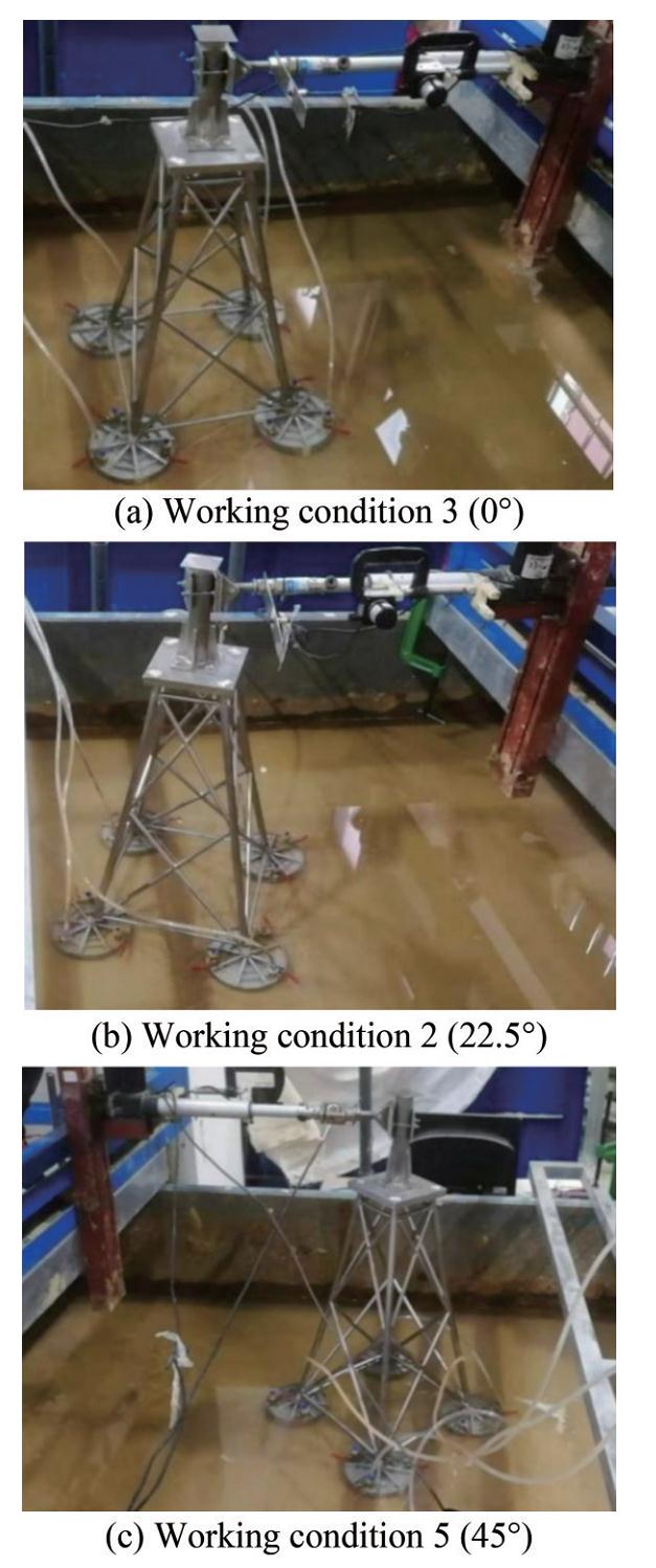 Figure 10 Position of the foundation at different loading directions
3.3.1 Impact on load-bearing performance
Table 6 compares the ultimate bearing capacity and corresponding ultimate displacement results of the foundation under different loading directions through tests and finite element calculations. Through the calculations, it can be concluded that with regard to the horizontal ultimate bearing capacity of the four-bucket jacket foundation loaded in different directions, as the loading direction increases, the horizontal bearing capacity of the foundation shows an increasing trend in the test and the finite element results. On this basis, it can be determined that loading is the most unfavorable direction in the α = 0° direction and most favorable in the α = 45° direction. The maximum difference between the finite element calculation results and relative test results is 8.3%, which does not exceed 10%. The maximum difference between the limit displacements is 17.3%, which does not exceed 20%. The trends of the finite element calculations and test results agree well, verifying the accuracy of the numerical simulations.
Table 6 Comparison of ultimate bearing capacity between tests and finite element calculationsLoading direction Displacement Load Test (m) Finite element (m) Phase difference ratio (%) Test (N) Finite element (N) Phase difference ratio (%) 0° 0.053 0.046 7 11.8 425 435 2.3 22.5° 0.058 0.048 1 17.0 462 445 3.7 45° 0.06 0.049 8 17.3 496 455 8.3 3.3.2 Effect on the bucket skirt pressure distribution
Figure 11 shows the finite element calculation results for the variation in the soil pressure of the bucket wall with the bucket height when the angle loading is 0°, 22.5°, and 45°. The red points in the diagram represent the position of the soil pressure on the contact surface of the bucket wall, the blue line represents the soil pressure on the outer wall of the bucket, and the black line represents the soil pressure on the inner wall of the bucket.
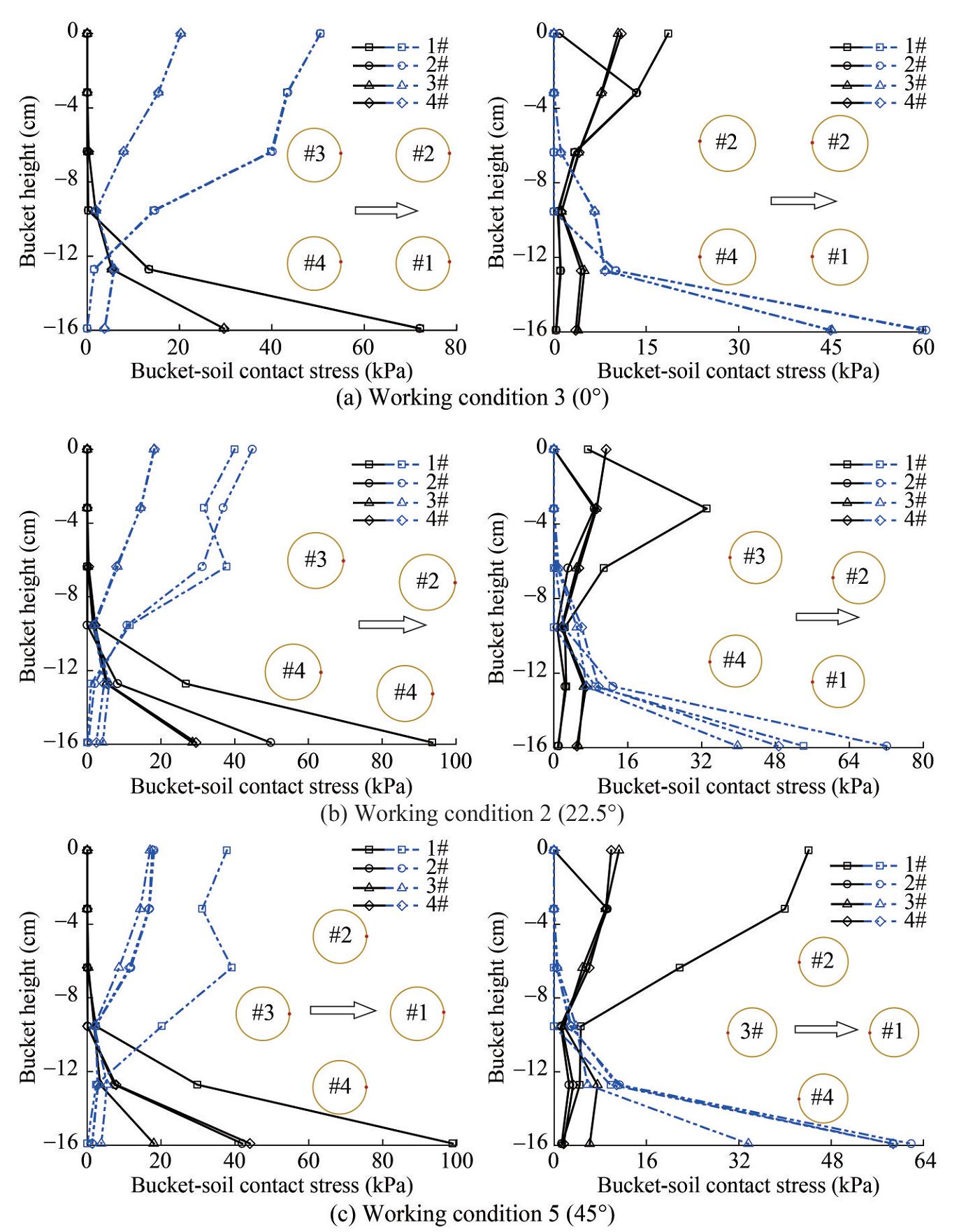 Figure 11 Soil pressure distribution of the foundation bucket wall with different bucket skirt heights
In this article, the side where the #3 and #4 buckets are located is defined as the backload side, and the opposite side of the #1 and #2 buckets is defined as the loading side. For a single bucket, this paper is mainly aimed at the bucket wall, with the plane where the central axis is located as the boundary, and the horizontal load is positive as the standard. The side with a positive normal vector outside the surface is defined as the loading direction, and the side with a negative normal vector outside the surface is defined as the loading direction. The soil pressure of the contact surface nodes was extracted from top to bottom along the height of the bucket side wall to study, and the soil pressure distribution of the contact surface of the bucket wall was obtained.
Figure 11 shows that under the three working conditions, the soil pressure on the outer wall of the #1 and #2 buckets decreases from top to bottom, the soil pressure at the bottom of the bucket gradually approaches 0, and the soil pressure on the inner wall of the bucket increases from top to bottom. These results are due to the tilt of the bucket under external loads and the location of the center of rotation below the midpoint of the bucket. With the center of rotation as the demarcation point, the soil pressure between the bucket and the soil is reversed, and the tension and compression transition to each other. The upper part of the outer wall of the bucket on the loading side belongs to the active soil pressure, the lower part of the bucket wall is the passive soil pressure, and the distribution of the soil pressure on the inner wall of the bucket is simply the opposite. For the 0° loading condition, the soil pressure on the inner and outer walls of the #1 and #2 loading side of the buckets basically coincide, the difference between the two gradually increases with increasing loading angle, and the change trend of the soil pressure on the inner and outer walls of the #1 and #2 buckets carrying side is opposite to that of the loading side. When the loading angle is 0°, due to the structure and load symmetry, the soil pressure distribution of the inner and outer bucket walls of the #3 and #4 buckets is identical to that of #1 and #2. When the loading angle is 45°, the earth pressure distribution of #2 and #3 is consistent, and the active soil pressure on the upper part of the outer wall of the #1 bucket is obviously greater than that of other working conditions.
Figure 12 shows the finite element calculation results for the soil pressure contour of the bucket top and inner wall in different loading directions. This figure shows that the passive soil pressure on the bucket is mainly concentrated at the bottom of the bucket. Among the four buckets, the active soil pressure on the top of the bucket foundation on the right side is larger, and the compression effect is obvious. The tension force on the soil on the left side is minuscule. In addition, as the load direction increases, the gradual transition from double buckets jointly bearing the load to a single bucket bearing the load alone gradually increases soil pressure on the right side. This result is consistent with the pattern of numerical curve results in Figure 10, further illustrating the correctness of the analysis.
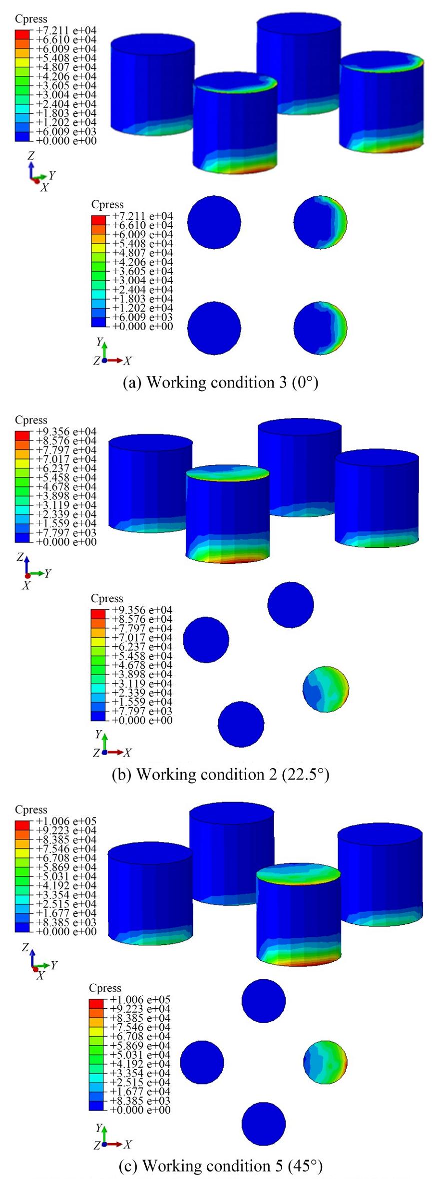 Figure 12 Soil pressure contour on the top and inner walls of the bucket
4 Conclusions
This paper conducted physical model tests and numerical calculations on the horizontal bearing capacity of the four-bucket jacket foundation in sand and reached the following conclusions:
1) The sealing of the bucket foundation has a great influence on the foundation-bearing capacity. The test results show that the horizontal ultimate bearing capacity in the unpressurized state is reduced by 51.3% compared with the pressurized state. Therefore, during the test process, the foundation must be in a sealed state to eliminate test errors caused by the sealing performance of the bucket foundation.
2) In the test, loading speeds of 3.25 and 1.85 mm/s were applied to the foundation to study the impact of loading speed on the foundation-bearing capacity. The results showed that the ultimate horizontal bearing capacity of the four-bucket jacket foundation is 465 N when the loading speed is 3.25 mm/s, 9.4% higher compared with a loading speed of 1.85 mm/s, indicating that the foundation's horizontal ultimate bearing capacity increases with the loading speed.
3) The four-bucket jacket foundation is loaded along the directions of 0°, 22.5°, and 45°. The load–displacement curve trends of the finite element calculation results and the test results are consistent. The loading direction of the four-bucket jacket foundation is the most unfavorable along the α = 0° direction and the most favorable along the α = 45° direction. Regarding the horizontal ultimate bearing capacity of the four-bucket jacket foundation loaded in different directions, the comparison error between the test and finite element results does not exceed 10%, so the two results can be considered similar.
Competing interest The authors have no competing interests to declare that are relevant to the content of this article. -
Figure 1 Jacket foundation of an offshore wind turbine
Figure 2 Test model of the four-bucket jacket foundation
Figure 3 Partial view of the test model
Figure 4 Test equipment
Figure 5 Loading direction definition
Figure 6 Bearing capacity of different models
Figure 7 Finite element model
Figure 8 Horizontal load – displacement curve under open/closed conditions of the bucket top valve
Figure 9 Horizontal load–displacement curves at different loading speeds
Figure 10 Position of the foundation at different loading directions
Figure 11 Soil pressure distribution of the foundation bucket wall with different bucket skirt heights
Figure 12 Soil pressure contour on the top and inner walls of the bucket
Table 1 Dimensions of the four-bucket jacket foundation model (mm)
Bucket diameter 159 Bucket space 159 Bucket skirt height 159 Bucket skirt and bucket top thickness 1.5 Overall height of the foundation 915 Table 2 Soil parameters
Density ρ (g/cm3) Internal friction angle φ(°) Cohesion c (kPa) Compression modulus Es (MPa) 2.2 34.46 3.27 18 Table 3 Main parameters of the instrument
Name Type Measuring range Accuracy Load device Micromachines 0–2 000 N ─ Pressure sensor Resistance strain gauge 0–30 t 0.5% με Displacement sensor Voltage strain gauge 0–1 m 0.2 mm Inclination sensor Micromachines ±15° ±0.001° Table 4 Calculation results of different finite element grids
Model Mesh number Ultimate bearing capacity Ultimate displacement Model 1 55 292 435.2 0.046 7 Model 2 110 446 432.1 0.047 4 Model 3 149 395 431.5 0.046 4 Model 4 290 904 419.4 0.040 4 Table 5 Test conditions
Working conditions Sealing state Loading speed (mm/s) Loading direction (°) 1 Not sealed 1.85 22.5 2 Sealed 1.85 22.5 3 Sealed 1.85 0 4 Sealed 3.25 0 5 Sealed 1.85 45 Table 6 Comparison of ultimate bearing capacity between tests and finite element calculations
Loading direction Displacement Load Test (m) Finite element (m) Phase difference ratio (%) Test (N) Finite element (N) Phase difference ratio (%) 0° 0.053 0.046 7 11.8 425 435 2.3 22.5° 0.058 0.048 1 17.0 462 445 3.7 45° 0.06 0.049 8 17.3 496 455 8.3 -
Ding H, Li J, Le C, Pan C, Zhang P (2022a) Shaking table tests of four-bucket jacket foundation for offshore wind turbines. China Ocean Engineering 36(6): 849-858. DOI: 10.1007/s11802-022-4742-7 Ding HY, Li YE, Zhang PY, Le CH (2022b) Experimental investigation of an offshore wind turbine four-bucket jacket foundation during lowering operation. Journal of Tianjin University (Science and Technology) 55(8): 792-801. (in Chinese) Ding HY, Yan RY, Zhang PY, Gan Y, He ZX (2023) Bearing characteristics of three bucket jacket foundation for offshore wind turbines in composite loading mode. Renewable Energy Resources 41(2): 207-214. (in Chinese) DOI: 10.13941/j.cnki.21-1469/tk.2023.02.005 Le CH, Pang YB, Zhang PY, Ding HY (2021) Torque-bearing capacity characteristics of the tetrapod suction bucket jacket foundation in sand. Journal of Harbin Engineering University 42(11): 1654-1662. (in Chinese) Li DY, Sun CP, Wang DL, Zhang YK (2023) Model Tests on The Bearing Capacity of Modified Suction Caisson under Inclined Pullout Loading. Journal of Disaster Prevention and Mitigation Engineering 43(4): 682-691. (in Chinese) DOI: 10.13409/j.cnki.jdpme.20190702001 Li JL, Guo YH, Lian JJ, Wang HJ (2022) Scour effects on the bearing capacity of multi-bucket jacket foundation for offshore wind turbines. Ocean Engineering 259: 111848 https://doi.org/10.1016/j.oceaneng.2022.111848 Lin YX, Zhang JY (2023) Development status and prospect of offshore wind power. Distributed Energy 8(2): 1-10. (in Chinese) DOI: 10.16513/j.2096-2185.DE.2308201 Liu Q, Wei K (2021) Reliability analysis of the jacket structure of offshore wind turbine considering environmental corrosion. Acta Energiae Solaris Sinica 42(8): 394-400. (in Chinese) DOI: 10.19912/j.0254-0096.tynxb.2019-0588 Luo XJ, Qu H, Deng XG (2023) Research on offshore wind turbine selection scheme. Mechanical and Electrical Information (3): 26-29+35. (in Chinese) DOI: 10.19514/j.cnki.cn32-1628/tm.2023.03.007 Mao YL, Du RG, Shi DD, Tian BY, Lu ZY, Zhang YK (2023) Construction and risk analysis of suction bucket jacket substructure for offshore wind turbines. China Harbour Engineering 43(4): 83-88. (in Chinese) Ruan J, Hu DS, Jia J (2022) Construction technologies of the suction bucket jacket foundation in offshore wind power projects. Hydropower and New Energy 36(4): 10-14. (in Chinese) DOI: 10.13622/j.cnki.cn42-1800/tv.1671-3354.2022.04.003 Wang JY, Sun GD, Chen GS, Yang X (2021) Finite element analyses of improved lateral performance of monopile when combined with bucket foundation for offshore wind turbines. Applied Ocean Research 111: 102647 https://doi.org/10.1016/j.apor.2021.102647 Wu X, Hu Y, Li Y, Yang J, Duan L, Wang T, Adcock T, Jiang Z, Gao Z, Lin Z, Borthwick A, Liao S (2019) Foundations of offshore wind turbines: A review. Renewable and Sustainable Energy Reviews 104: 379-393. DOI: 10.1016/j.rser.2019.01.012 Xu J, Ding X, Tang HN (2022) Pullout bearing characteristics of bucket foundation for floating offshore wind turbine. Ship Engineering 44(7): 162-170. (in Chinese) DOI: 10.13788/j.cnki.cbgc.2022.07.25 Zhang P, Qi X, Yan R, Xu Y, Le C, Ding H (2022a) Penetration resistance of composite bucket foundation with eccentric load for offshore wind turbines. Journal of Ocean University of China 21(6): 1454-1466 https://doi.org/10.1007/s11802-022-4988-0 Zhang PY, Feng JC, Li XL, Zhang JF, Le CH, Ding HY (2022b) Influence of different soil on horizontal bearing characteristics of tripod suction jacket foundations. Acta Energiae Solaris Sinica 44(4): 189-194. (in Chinese) DOI: 10.19912/j.0254-0096.tynxb.2022-0270 Zhang PY, Ma YX, Le CH, Ding HY (2023a) Experimental study on tilt adjustment technique of tripod bucket jacket foundation for offshore wind turbine in sand. Journal of Marine Science and Application 21: 192-204. DOI: 10.1007/s11804-022-00308-4 Zhang PY, Qi X, Ding HY, Le CH, Lin YF, Xiao JD (2023b) Bearing characteristics of mono-column composite bucket foundation in sand for offshore wind turbines. Ocean Engineering 280: 114870 https://doi.org/10.1016/j.oceaneng.2023.114870 Zhu H, Li MC, Guo YH, Yang X, Wang HJ, Lian JJ (2022) Analysis of foundation stress and floating of deepwater offshore wind power three-bucket jacket. Acta Energiae Solaris Sinica 43(11): 269-276. (in Chinese) DOI: 10.19912/j.0254-0096.tynxb.2021-0471
