
Consideration of Aspect Ratios on Flow Around Wall-mounted Square Cylinders
https://doi.org/10.1007/s11804-025-00663-y
-
Abstract
Flow characteristics around a wall-mounted square cylinder have been numerically simulated at aspect ratios (AR) ranging from 4 to 7 at Re = 10 000. Four turbulence models have been compared in terms of drag coefficient (CD). The closest result has been provided by two turbulence models, namely, k − ε Realizable and k − ω Shear Stress Transport (SST). Hence, these models were utilized to present the flow patterns of pressure distributions, turbulent kinetic energy values, velocity magnitude values with streamlines, streamwise velocity components, cross-stream velocity components and spanwise velocity components on different planes. Flow stagnation has been attained in front of the cylinder. Pressure values peaked for the upstream region. Over the cylinders, the tip vortex structure was dominant owing to the influence of the free end. Flow separation from the top front edge of the body has been obtained. The dividing streamline affected by the flow separation was highly effective in the wake region and moved nearer to the body when the aspect ratio was decreased; the reason was the wake shrinkage owing to the decreasing aspect ratio. Upwash and downwash have been seen in the cylinder wake. These two models presented similar flow patterns and drag coefficients. These drag coefficients are in good agreement with those in previous studies.-
Keywords:
- Aspect ratio ·
- Drag coefficient ·
- Reynolds number ·
- Turbulence model ·
- Wall-mounted square cylinder
Article Highlights● Flow around a wall-mounted square cylinder has been examined for aspect ratios from 4 to 7.● Four RANS-based turbulence models have been considered for numerical study.● Two models exhibited similar flow patterns and drag coefficients in good agreement with those presented in past studies. -
1 Introduction
Three-dimensional and complex flow patterns are differently observed for the cases of wall-mounted cylinders having the effects of aspect ratios (Rinoshika et al., 2021). These patterns have a greater influence on the flow properties around a finite cylinder compared with those of an infinite one (Aboueian et al., 2021). Thus, studies have focused on the wake dynamics of wall-mounted cylinders, such as antennas, chimneys, cooling towers, offshore platforms, skyscrapers, stacks and submarine appendages (Sumner, 2013, Behera and Saha, 2021, Yousif and Lim, 2022). For these examples, their flow characteristics are isochronously affected due to the bottom wall and the free end of the wall-mounted cylinder (Essel et al., 2021). The effects of free end and cylinder-wall junction on three-dimensional flow fields over the body are obtained as vortex shedding, horseshoe vortex structure and recirculation region in the wake (Sumner, 2013). As stated by Sumner et al. (2004), the aspect ratio is an important parameter that ranges from 1 to 7. Various Reynolds numbers have been considered for wall-mounted cylinders (Hosseini et al., 2013, McClean and Sumner, 2014, Kumar and Tiwari, 2019, Da Silva et al., 2020). Yuhi et al. (1999) simulated the flow field of a wall-mounted circular cylinder. Roh and Park (2003) visualized the flow patterns of a circular cylinder mounted on a flat plate using various aspect ratios at and two different Reynolds numbers. A wall-mounted circular cylinder has been used by Afgan et al. (2007) for the investigation of turbulent flow conditions via Large Eddy Simulation (LES) turbulence model. Ozturk et al. (2008) observed the upstream and downstream flow structures of a circular cylinder positioned on a flat plate. Particle Image Velocimetry (PIV) method has been considered in their study for the range of 750 ≤ Re ≤ 9 600. Bocu and Altac (2011) considered the aspect ratio effect for the circular cylinders on heat transfer by natural convection in terms of pin arrays. Krajnović (2011) studied flow dynamics around a circular cylinder mounted on a ground plane by implementing a LES turbulence model. Different aspect ratios have been taken into account for Re = 20 000. Uffinger et al. (2013) investigated the flow fields in the vicinity of various wall-mounted cylinders by utilizing experimental and numerical techniques. El Hassan et al. (2015) used a PIV system to examine flow around a wall-mounted rectangular cylinder at Re = 12 000. Kirkil and Constantinescu (2015) examined the flow characteristics of a surface-mounted circular cylinder using experimental and numerical methods. Vinuesa et al. (2015) considered the flow structures of a wall-mounted square cylinder at Re = 1 000. As a method, Direct Numerical Simulation (DNS) has been applied for their problem. Schanderl and Manhart (2016) applied LES turbulence model for a wall-mounted circular cylinder at Re = 39 000. The problem with a wall-mounted circular cylinder has also been considered in a study by Dey et al. (2018). For higher Reynolds number, flow structures of a wall-mounted square cylinder have been examined by Mercier et al. (2020). For the investigation of flow characteristics, Goktepeli et al. (2021) mounted rectangular and square cross-sectional ribs on plates in the experimental study. Rastan et al. (2021) implemented LES turbulence model to examine the flow characteristics around a wall-mounted rectangular cylinder at Re = 12 000. Various experiments have been conducted to validate the numerical results. In a numerical study, Hammad et al. (2022) scrutinized the effects of chamfers on flow dynamics around wall-mounted square cylinders at Re = 12 000. Martínez-Sánchez et al. (2023) investigated the flow characteristics around a wall-mounted square cylinder. Matsui et al. (2024) measured the distribution of pressure fluctuations for a flat wall behind the square cylinder. In their experimental study, Yousif et al. (2024) considered the flow characteristics around a wall-mounted cylinder.
Regarding its significance for engineering applications, this work numerically investigated the flow characteristics of wall-mounted square cylinders with different aspect ratios by the turbulence models. The values for the aspect ratios have been determined with respect to the critical range for this problem. The Reynolds number of Re = 10 000 was set for the numerical simulations of three-dimensional wake dynamics. Evaluations of turbulence models with this Reynolds number are rare. The distinguishing point of this study was the comparison of various methods at Re = 10 000. However, experimental facilities for fluid mechanics may not be available, and numerically simulating the flow characteristics around a cylinder is crucial to determining the appropriate turbulence model. Therefore, validated results are crucial for future studies on this problem.
2 Turbulence modeling
Due to three-dimensional complex flow dynamics around a wall-mounted cylinder, vortices are strongly observed for varying scales. Therefore, eddy-based flows are significantly effective for the present study. In this perspective, different turbulence models have been implemented at Re = 10 000.
Continuity and momentum equations are given in Equations (1) and (2) (Yagmur et al., 2020, Goktepeli and Atmaca, 2023):
$$ \frac{\partial \rho}{\partial t}+\frac{\partial}{\partial x_i}\left(\rho u_i\right)=0 $$ (1) $$ \begin{aligned} \frac{\partial}{\partial t}\left(\rho u_i\right)+ & \frac{\partial}{\partial x_i}\left(\rho u_i u_j\right)=-\frac{\partial \rho}{\partial x_i}+ \\ & \frac{\partial}{\partial x_j}\left[\mu\left(\frac{\partial u_i}{\partial x_j}+\frac{\partial u_j}{\partial x_i}-\frac{2}{3} \delta_{i j} \frac{\partial u_l}{\partial x_l}\right)\right]+\frac{\partial}{\partial x_j}\left(-\rho \overline{x_i^{\prime} x_j^{\prime}}\right) \end{aligned} $$ (2) The velocity components for the related coordinates have been given in these equations. The terms for density and dynamic viscosity have also been presented. Mean flow properties requiring less computational capacity have been considered for the present problem. Thus, the methods based on k − ε and k − ω turbulence models have been utilized in terms of Reynolds-Averaged Navier-Stokes (RANS) techniques.
As one of k−ε turbulence models, the Realizable module is modified technique compared to other derivatives. This model is widely utilized for rotational and boundary-free shear flows. As in Equations (3) and (4), k is turbulent kinetic energy and its dissipation rate is ε (Goktepeli et al., 2020; Yagmur et al., 2020; Goktepeli and Atmaca, 2023):
$$ \frac{\partial}{\partial t}(\rho k)+\frac{\partial}{\partial x_i}\left(\rho k u_i\right)=\frac{\partial}{\partial x_j}\left[\mu \frac{\partial k}{\partial x_j}\right]+G_k-\rho \varepsilon+S_k $$ (3) $$ \begin{array}{r} \frac{\partial}{\partial t}(\rho \varepsilon)+\frac{\partial}{\partial x_i}\left(\rho \varepsilon u_i\right)=\frac{\partial}{\partial x_j}\left[\mu \frac{\partial k}{\partial x_j}\right]+ \\ \rho C_1 S_{\varepsilon}-\rho C_2 \frac{\varepsilon^2}{k+\sqrt{v \varepsilon}}+S_{\varepsilon} \end{array} $$ (4) Generation of turbulent kinetic energy is Gk due to the average velocity gradients. Sk and Sε are the source terms (Goktepeli et al., 2020; Yagmur et al., 2020; Goktepeli and Atmaca, 2023).
As a turbulence model, k−ω SST is preferred in cases of interaction between fluid and structure, free shear layers, reverse pressure gradients. There is replacement for turbulent viscosity owing to the transport for turbulent shear stress. Cross-diffusion for ω and mixing function are needed. After the process, this turbulence model becomes more effective in the near-wall and far-field zones. As given in Equations (5) and (6), the transport equations for k−ω SST model are used (Goktepeli et al., 2020; Yagmur et al., 2020; Goktepeli and Atmaca, 2023):
$$ \frac{\partial}{\partial t}(\rho k)+\frac{\partial}{\partial x_i}\left(\rho k u_i\right)=\frac{\partial}{\partial x_j}\left[\varGamma_k \frac{\partial k}{\partial x_j}\right]+G_k-Y_k+S_k $$ (5) $$ \frac{\partial}{\partial t}(\rho \omega)+\frac{\partial}{\partial x_i}\left(\rho \omega u_i\right)=\frac{\partial}{\partial x_j}\left[\varGamma_\omega \frac{\partial \omega}{\partial x_j}\right]+G_\omega+D_\omega-Y_\omega+S_\omega $$ (6) Generation of turbulent kinetic energy is Gk while Gω is for the generation of ω. Terms of Γk and Γω are considered as the effective diffusivity of k and ω, respectively. Dissipation terms of k and ω are Yk and Yω, respectively. The cross-diffusion term is Dω while the derivations of both Sk and Sω are the user-defined ones (Goktepeli et al., 2020; Yagmur et al., 2020; Goktepeli and Atmaca, 2023).
As given in Figure 1, three-dimensional flow domain has been generated by considering the dimensions of −10 ≤ x* = x/d ≤ 25, 0 ≤ y* = y/d ≤ 20 and −10 ≤ z* = z/d ≤ 10 for streamwise, cross-stream and spanwise directions, respectively. All dimensions have been divided by the edge length (d) for the cylinder. The aim is to obtain non-dimensional terms. The square cylinder has been positioned in the intersection of x* = y* = z* = 0. The aspect ratios of the cylinder have been considered for 4 ≤ AR = h/d ≤ 7 given for the ratio of the cylinder height to the upstream edge length.
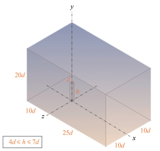 Figure 1 Three-dimensional flow domain
The value of uniform velocity is U∞ = 1 m/s defined as the inlet boundary condition. The Reynolds number is based on the edge length of d = 0.01 m and calculated as Red = U∞ d/v = 10 000. Here, the kinematic viscosity of water is considered. The pressure outlet has been defined by gauge pressure in the exit that is freely open to the atmosphere. No-slip boundary condition has been used for all the surfaces of the square cylinder. The same boundary condition has also been applied for the bottom wall where the cylinder mounted on. Meanwhile, the symmetrical boundary condition has been implemented for the other walls of the computational domain.
Face meshing has been applied for eleven faces of the flow domain. Inflation has been defined for the square cylinder. Total thickness has been applied for twenty layers. The growth rate was 1.05 and the maximum thickness was 1 mm. The grid structure around the square cylinder is shown in Figure 2.
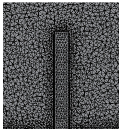 Figure 2 Grid structure around the square cylinder
Various grid numbers of 3.5 × 10⁶, 4.9 × 10 6, 7.1 × 10⁶ and 10 × 106 have been compared with respect to the drag coefficient as shown in Figure 3. The effect of turbulence modeling has also been indicated in the mentioned chart for AR = 7. The maximum deviation obtained is less than 1% for the grid numbers in a row. According to the results of grid independence tests for the drag coefficient, the values for the grid numbers of 4.9 × 10⁶ and 7.1 × 10⁶ are close. For these grid structures, the minimum deviation in drag coefficient is around 0.12% and the maximum deviation is approximately 0.54%. Therefore, the grid number of 4.9 × 10⁶ has been used for numerical simulations. The solution convergence has been determined as the criterion of 10−6 for all the equations of continuity, momentum and turbulence models. Given their success for the drag coefficient, the numerical results have been presented for the turbulence models of k−ε Realizable and k−ω SST due to their success for drag coefficients. For different aspect ratios, area-weighted average values for non-dimensional wall distance have been attained as 0.66 ≤ y+ ≤ 0.68 for k −ε Realizable turbulence model and 0.64 ≤ y+ ≤ 0.65 for the k −ω SST turbulence model. Therefore, the results from these two turbulence models are in good agreement with the values in the literature (Uffinger et al., 2013, McClean and Sumner, 2014). For this reason, these turbulence models have been chosen for the examination of flow characteristics around wall-mounted square cylinders.
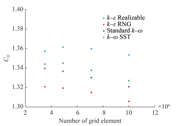 Figure 3 Effects of grid number on the drag coefficient of turbulence models
The effects of grid number on the streamwise velocity components through the x-direction have been presented for different turbulence models in Figures 4‒7. Similarly, for the turbulence models of k−ε Realizable and k−ω SST, the limited changes have been observed with respect to varying grid numbers.
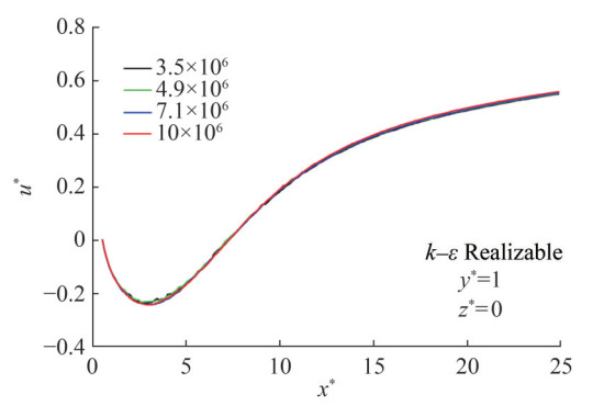 Figure 4 Effects of grid number on the streamwise velocity components of k−ε Realizable turbulence model
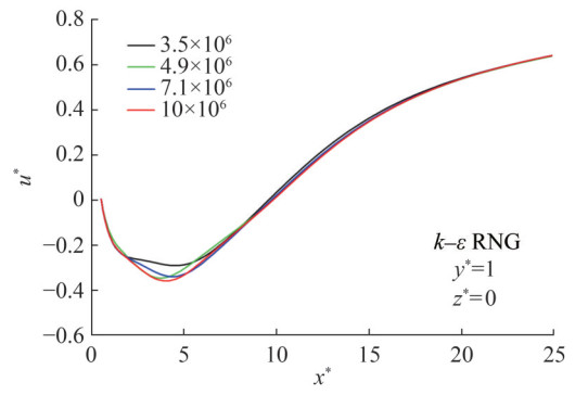 Figure 5 Effects of grid number on the streamwise velocity components of k−ε RNG turbulence model
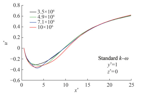 Figure 6 Effects of grid number on the streamwise velocity components of Standard k−ω turbulence model
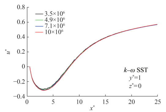 Figure 7 Effects of grid number on the streamwise velocity components of k−ω SST turbulence model
3 Results and discussion
The flow around a square cylinder has been investigated for Re = 10 000 by considering the effect of aspect ratios via the turbulence models. All values of the contour graphics have been presented as non-dimensional by the free-stream velocity. The mutual legend bar has been utilized for each chart given for the same property.
The pressure values have also been given in the dimensionless form in the equation of P* = Pρ−1U∞−2. The maximum value is P*max = 0.54, and the minimum is P*min = − 0.28 for the planes at y* = 3 and z* = 0. The legend includes fifteen divisions for Figures 8 and 9. In terms of flow direction, the upstream and downstream zones have been shown for −10 ≤ x* ≤ 25 for the plane of y* = 3 and − 5 ≤ x* ≤ 10 for the plane of z* = 0. Flow stagnation is achieved in front of the square cylinder. Therefore, maximum pressure values have been provided for the upstream region. This area became larger as aspect ratio of cylinder increased. For the results of k − ε Realizable turbulence model, the maximum pressure regions are also larger than those of the k−ω SST turbulence model. On the contrary, minimum pressure zones have been observed over the square cylinders due to the separated flow. This region dominates the numerical results obtained by the k−ω SST turbulence model. For the wake region, low-pressure regions have been attained and these zones were narrower for the results of k−ε Realizable turbulence model. As a result of increasing aspect ratio, pressure difference between the upstream and downstream regions tends to increase. Nonetheless, the pressure drop for the numerical results attained by the k−ω SST turbulence model is greater than that for the numerical results of the k−ε Realizable turbulence model.
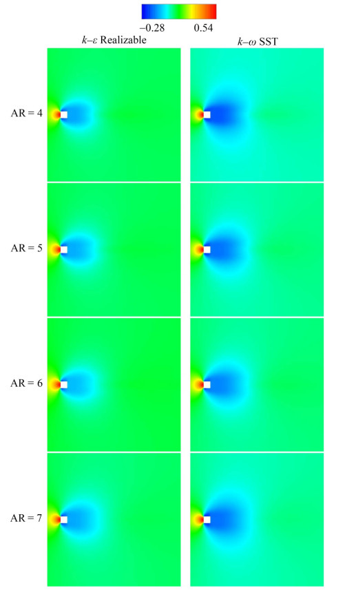 Figure 8 Dimensionless pressure distributions around square cylinders with various aspect ratios for the plane at y* = 3
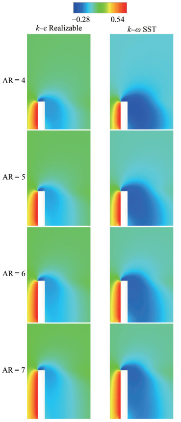 Figure 9 Dimensionless pressure distributions around square cylinders with various aspect ratios for the plane at z* = 0
Velocity magnitude values including streamline patterns have been given in the form of U* = UU∞−1. As in the legend with fifteen divisions, the maximum value is U*max = 1.15 while the minimum one is U*min = 0. The values have been given for −10 ≤ x* ≤ 25 for the plane of y* = 3 and − 5 ≤ x* ≤ 10 for the plane of z* = 0, as displayed in the contour graphics of Figures 10 and 11. The flow stagnation point constitutes the boundary between the flows that are directed either upward or downward and moves closer to the free end since the aspect ratio increased also stated by Sumner et al. (2017). Over the square cylinders, the tip vortex system is dominant due to the free end effect. Flow separation from the top front edge of the square cylinder is observed, indicating rotation toward the base prior to flow reattachment (Behera and Saha, 2021). A horseshoe flow structure appears in front of the cylinder; however, the influence of aspect ratio on this flow is limited. The dividing streamline triggered by the flow separation is effective in the cylinder wake. Furthermore, this streamline moves closer to the body because the wake region tends to shrink. Upwash and downwash transpire in the wake region. Base eddy has been seen with respect to flow patterns over the surface. Secondary flow caused by the interaction of wake flow and main flow is also noted. The numerical results obtained by the turbulence models exhibit similarity in terms of velocity magnitude.
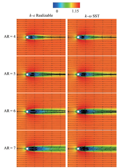 Figure 10 Dimensionless velocity magnitude values with streamline patterns around square cylinders with various aspect ratios for the plane at y* = 3
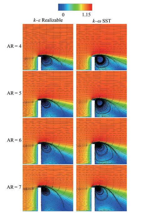 Figure 11 Dimensionless velocity magnitude values with streamline patterns around square cylinders with various aspect ratios for the plane at z* = 0
The streamwise velocity components have been depicted by the values of u* = uU∞−1. The peak value is u*max = 1.15 and the minimum value is u*min = −0.35 as shown by the legend having fifteen divisions. These values are valid for −10 ≤ x* ≤ 25 for the plane of y* = 3 and −5 ≤ x* ≤ 10 for the plane of z* = 0 as shown in Figures 12 and 13. The numerical results of different turbulence models are nearly similar. The flow stagnation point is the boundary for upward and downward flows. The tip vortex structure is effective because of the free end effect. Flow separation due to the top front edge has been observed for the cylinder. A horseshoe vortex system appears in front of the square cylinder. Nonetheless, the aspect ratio is nearly ineffective for the flow phenomenon. For the wake flow, the dividing streamline is dominant owing to the flow separation. In addition, the dividing streamline moves closer to the cylinder because of the decreasing aspect ratio. The reason is the enlargement of the wake region caused by increasing the aspect ratio. Upwash and downwash also transpire in the cylinder wake. Bottom wall vortices have been observed by considering the flow characteristics affected by the ground. For this reason, secondary flow has been attained owing to the interaction of main and wake flows.
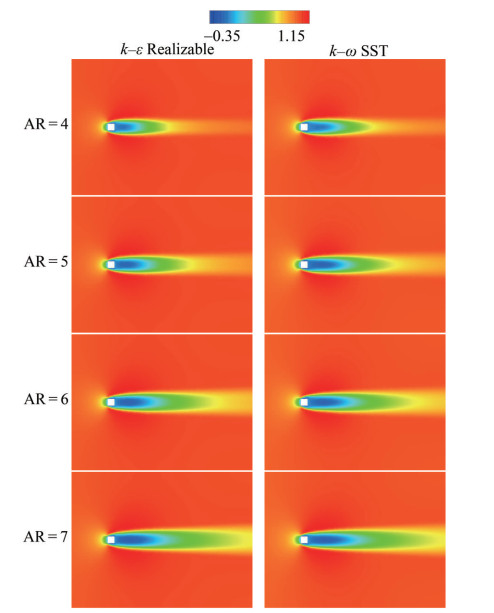 Figure 12 Dimensionless streamwise velocity components around square cylinders with various aspect ratios for the plane at y* = 3
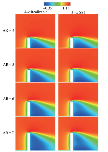 Figure 13 Dimensionless streamwise velocity components around square cylinders with various aspect ratios for the plane at z* = 0
Cross-stream velocity components have been presented for the plane of z* = 0 for v* = vU∞−1. The maximum and minimum values are v*max = 0.7 and v*min = −0.3, respectively, as shown in the legend including fifteen divisions. These values are within the range of −5 ≤ x* ≤ 10 for the plane of z* = 0, as displayed in Figure 14. The maximum value has been obtained around the top front edge of the square cylinder due to flow separation. However, the minimum values have been observed in the vicinity of the bottom corner at the upstream and in the wake region. The sizes of the upstream clusters are nearly the same. Nonetheless, the cluster with a negative value is larger in the wake region. Since the boundary layer effect on the ground was dominant, the larger cluster with a positive value has not been observed for the far wake. The reason is the damping by the negative values in the wake region. This situation is especially effective in the near-wake region. The numerical results attained by all the turbulence models present similarity in terms of cross-stream velocity components.
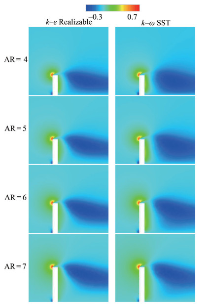 Figure 14 Dimensionless cross-stream velocity components around square cylinders with various aspect ratios for the plane at z* = 0
The spanwise velocity components have been presented for w* = wU∞−1. The maximum and minimum values are w*max = 0.75 and w*min = −0.75, respectively, as shown in the legend including fifteen divisions. The values are within the range of −5 ≤ z* ≤ 5 for the plane of x* = 0 and −10 ≤ x* ≤ 25 for the plane of y* = 3, as illustrated in Figures 15 and 16. For the plane of x* = 0, the maximum value is found on the negative z-axis, and the minimum is on the positive side of the z-direction. For the plane of y* = 3, the maximum value is also observed around the top front corner, and the minimum is around the bottom front corner. The mean value is attained due to the damping of the opposite values. These results are approximately the same for all the turbulence models.
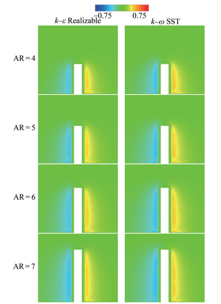 Figure 15 Dimensionless spanwise velocity components around square cylinders with various aspect ratios for the plane at x* = 0
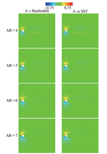 Figure 16 Dimensionless spanwise velocity components around square cylinders with various aspect ratios for the plane at y* = 3
The turbulent kinetic energy is given as TKE* = TKE U∞−2 in different planes, as shown in Figures 17 and 18. The maximum and minimum values are TKE*max = 0.05 and TKE*min = 0, respectively, for the legend of fifteen divisions. These values are distributed within − 10 ≤ x* ≤ 25 for the plane of y* = 3 and −5 ≤ x* ≤ 10 for the plane of z* = 0. Owing to the turbulence triggered by the separated flow, the maximum value has been obtained in the wake region of the square cylinder. In addition, the turbulence intensity in the wake region of the cylinder was relatively high due to the influence of local fluctuations. Moreover, two independent clusters are observed due to the flow separation. Larger clusters are seen owing to the increment of aspect ratio. For lower aspect ratios, these clusters are also closer to the body. However, the maximum values are dominant in the wake region with respect to the numerical results of the k−ω SST turbulence model. Therefore, the retardation of flow recovery has also been obtained because of the same effect. On the other hand, the clusters with maximum values are very effective over the free end of the cylinder for the results of k−ε Realizable turbulence model.
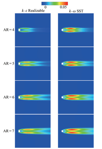 Figure 17 Dimensionless turbulent kinetic energy values around square cylinders with various aspect ratios for the plane at y* = 3
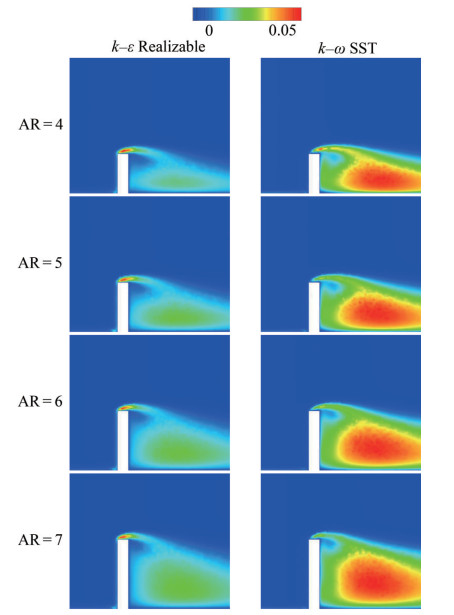 Figure 18 Dimensionless turbulent kinetic energy values around square cylinders with various aspect ratios for the plane at z* = 0
The streamwise velocity profiles have been presented for three different positions in the wake regions of the square cylinders. These stations are x* = 1, x* = 3 and x* = 5 as given in Figure 19. The velocity profile is U-shaped for the near-wake region of the square cylinder but turns into a V-shape by moving away from the body as also stated by Aksoy et al. (2024). Different velocity profiles are obtained because of turbulence modeling. Nonetheless, the influence of aspect ratio is relatively low. The minimum values have been attained by the turbulence model of k − ω SST. With the increasing aspect ratio, the minimum value of each case also tends to increase. Moreover, an increment in velocity values is indicated by movement away from the symmetry axis. The maximum values of each case are nearly the same and are seen in the interaction point of the main and wake flows. However, the difference between these values shows an increasing trend for the far wake.
 Figure 19 Streamwise velocity profiles for different aspect ratios obtained using two turbulence models
The results of the present study have also been presented in terms of drag coefficients. Drag coefficient (CD) is one of dimensionless numbers for flow around bluff bodies (Qiu et al., 2017, Aksoy et al., 2023). With respect to the values given in Table 1, the results of the k −ε Realizable and k − ω SST turbulence models are close to each other and are in good agreement with previous studies. A comparison between the two revealed the k−ω SST turbulence model to be more successful. The drag coefficient tends to increase due to increment of aspect ratios of the square cylinders. The results of this study have been validated by the values of different studies done on similar problems. For this kind of problem, the effect of Reynolds number is limited with respect to these values. However, as expected, the influence of the aspect ratio for the square cylinder is more obvious in terms of wall-mounted bodies.
Table 1 Comparison of drag coefficients for varying aspect ratiosStudy Method Re AR CD Uffinger et al. (2013) Experimental 12 800 6 1.41 McClean and Sumner (2014) Experimental 73 000 3–11 1.29–1.46 da Silva et al. (2020) LES turbulence model 500 3 1.33 Behera and Saha (2021) LES turbulence model 10 000 7 1.253 Present study k−ε Realizable turbulence model 10 000 4–7 1.258–1.345 k−ω SST turbulence model 1.269–1.361 4 Conclusions
Flow patterns around a wall-mounted square cylinder with finite height have been numerically investigated at Re = 10 000 using different turbulence models. Wall-mounted square cylinders are encountered in engineering applications including chimneys, cooling towers, skyscrapers and stacks. The effects of the aspect ratios from AR = 4 to AR = 7 on flow characteristics have been considered. Four RANS-based turbulence models were tested for drag coefficient estimation. Results show that the closest values are obtained by k−ε Realizable and k−ω SST turbulence models. Hence, these methods have been used for the presentation of flow characteristics such as pressure distributions, turbulent kinetic energy values, velocity magnitude values with streamlines, streamwise velocity components, cross-stream velocity components and spanwise velocity components on several planes. Flow stagnation is observed in front of the square cylinder. Therefore, the highest values for pressure are obtained for the upstream region of the square cylinder. Over the cylinders, the tip vortex system is dominant because of the free end effect. Flow separation from the top front edge of the cylinder has been attained. In the wake region of the square cylinder, an effective dividing streamline is formed due to the flow separation. What is more, the streamline is nearer to the body for decreasing aspect ratios. Because there is wake shrinkage owing to decreasing aspect ratio. The upwash and the downwash have been seen in the square cylinder wake. Base eddy has been observed with respect to flow structures on the bottom wall. The two turbulence models present similar flow patterns. The drag coefficients have been obtained. These values are 1.258 ≤ CD ≤ 1.345 and 1.269 ≤ CD ≤ 1.361 by k−ε Realizable and k−ω SST turbulence models for increasing aspect ratios from 4‒7, respectively. The numerical results are in good agreement with those obtained in past studies, RANS-based turbulence models could be preferred to decrease the computational cost and time requirement. The experimental facilities may not be available for fluid mechanics. However, the numerical simulation of the flow characteristics around a cylinder is very important for the determination of the turbulence model. For this reason, the validated results are very crucial for future studies on the present problem.
Competing interest The author has no competing interests to declare that are relevant to the content of this article. -
Figure 1 Three-dimensional flow domain
Figure 2 Grid structure around the square cylinder
Figure 3 Effects of grid number on the drag coefficient of turbulence models
Figure 4 Effects of grid number on the streamwise velocity components of k−ε Realizable turbulence model
Figure 5 Effects of grid number on the streamwise velocity components of k−ε RNG turbulence model
Figure 6 Effects of grid number on the streamwise velocity components of Standard k−ω turbulence model
Figure 7 Effects of grid number on the streamwise velocity components of k−ω SST turbulence model
Figure 8 Dimensionless pressure distributions around square cylinders with various aspect ratios for the plane at y* = 3
Figure 9 Dimensionless pressure distributions around square cylinders with various aspect ratios for the plane at z* = 0
Figure 10 Dimensionless velocity magnitude values with streamline patterns around square cylinders with various aspect ratios for the plane at y* = 3
Figure 11 Dimensionless velocity magnitude values with streamline patterns around square cylinders with various aspect ratios for the plane at z* = 0
Figure 12 Dimensionless streamwise velocity components around square cylinders with various aspect ratios for the plane at y* = 3
Figure 13 Dimensionless streamwise velocity components around square cylinders with various aspect ratios for the plane at z* = 0
Figure 14 Dimensionless cross-stream velocity components around square cylinders with various aspect ratios for the plane at z* = 0
Figure 15 Dimensionless spanwise velocity components around square cylinders with various aspect ratios for the plane at x* = 0
Figure 16 Dimensionless spanwise velocity components around square cylinders with various aspect ratios for the plane at y* = 3
Figure 17 Dimensionless turbulent kinetic energy values around square cylinders with various aspect ratios for the plane at y* = 3
Figure 18 Dimensionless turbulent kinetic energy values around square cylinders with various aspect ratios for the plane at z* = 0
Figure 19 Streamwise velocity profiles for different aspect ratios obtained using two turbulence models
Table 1 Comparison of drag coefficients for varying aspect ratios
Study Method Re AR CD Uffinger et al. (2013) Experimental 12 800 6 1.41 McClean and Sumner (2014) Experimental 73 000 3–11 1.29–1.46 da Silva et al. (2020) LES turbulence model 500 3 1.33 Behera and Saha (2021) LES turbulence model 10 000 7 1.253 Present study k−ε Realizable turbulence model 10 000 4–7 1.258–1.345 k−ω SST turbulence model 1.269–1.361 -
Aboueian J, Sohankar A, Rastan MR, Ghodrat M (2021) An experimental study on flow over two finite wall-mounted square cylinders in a staggered arrangement. Ocean Engineering 240: 109954. https://doi.org/10.1016/j.oceaneng.2021.109954 Afgan I, Moulinec C, Prosser R, Laurence D (2007) Large eddy simulation of turbulent flow for wall mounted cantilever cylinders of aspect ratio 6 and 10. International Journal of Heat and Fluid Flow 28(4): 561-574. https://doi.org/10.1016/j.ijheatfluidflow.2007.04.014 Aksoy MH, Goktepeli I, Ispir M, Cakan A (2023) Machine learning approach for flow fields over a circular cylinder based on particle image velocimetry measurements. Measurement 223: 113699. https://doi.org/10.1016/j.measurement.2023.113699 Aksoy MH, Yagmur S, Dogan S, Goktepeli I, Ispir M (2024) Experimental study on cylinder wake control using forced rotation. Journal of Wind Engineering and Industrial Aerodynamics 246: 105662. https://doi.org/10.1016/j.jweia.2024.105662 Behera S, Saha AK (2021) Effect of inlet shear on turbulent flow past a wall-mounted finite-size square cylinder. Ocean Engineering 234: 109270. https://doi.org/10.1016/j.oceaneng.2021.109270 Bocu Z, Altac Z (2011) Laminar natural convection heat transfer and air flow in three-dimensional rectangular enclosures with pin arrays attached to hot wall. Applied Thermal Engineering 31(16): 3189-3195. https://doi.org/10.1016/j.applthermaleng.2011.05.045 Da Silva BL, Chakravarty R, Sumner D, Bergstrom DJ (2020) Aerodynamic forces and three-dimensional flow structures in the mean wake of a surface-mounted finite-height square prism. International Journal of Heat and Fluid Flow 83: 108569. https://doi.org/10.1016/j.ijheatfluidflow.2020.108569 Dey S, Swargiary D, Sarkar S, Fang H, Gaudio R (2018) Turbulence features in a wall-wake flow downstream of a wall-mounted vertical cylinder. European Journal of Mechanics-B/Fluids 69: 46-61. https://doi.org/10.1016/j.euromechflu.2018.01.003 El Hassan M, Bourgeois J, Martinuzzi R (2015) Boundary layer effect on the vortex shedding of wall-mounted rectangular cylinder. Experiments in Fluids 56: 1-19. https://doi.org/10.1007/s00348-014-1882-6 Essel EE, Tachie MF, Balachandar R (2021) Time-resolved wake dynamics of finite wall-mounted circular cylinders submerged in a turbulent boundary layer. Journal of Fluid Mechanics 917: A8. https://doi.org/10.1017/jfm.2021.265 Goktepeli I, Atmaca U (2023) Examination of air flow characteristics over an open rectangular cavity between the plates. International Journal of Aeroacoustics 22(3-4): 351-370. https://doi.org/10.1177/1475472X231185082 Goktepeli I, Atmaca U, Cakan A (2020) Investigation of heat transfer augmentation between the ribbed plates via Taguchi approach and Computational Fluid Dynamics. Journal of Thermal Science 29(3): 647-666. https://doi.org/10.1007/s11630-019-1155-z Goktepeli I, Atmaca U, Yagmur S (2021) Visualization of flow characteristics between the ribbed plates via Particle Image Velocimetry. Thermal Science 25(1A): 171-179. https://doi.org/10.2298/TSCI180727300G Hammad A, Younis MY, Akram N, Uddin E, Javed A (2022) Simulation study on flow behavior around a wall-mounted finite height square cylinder with corner chamfer. Journal of Wind Engineering and Industrial Aerodynamics 229: 105157. https://doi.org/10.1016/j.jweia.2022.105157 Hosseini Z, Bourgeois JA, Martinuzzi RJ (2013) Large-scale structures in dipole and quadrupole wakes of a wall-mounted finite rectangular cylinder. Experiments in Fluids 54: 1-16. https://doi.org/10.1007/s00348-013-1595-2 Kirkil G, Constantinescu G (2015) Effects of cylinder Reynolds number on the turbulent horseshoe vortex system and near wake of a surface-mounted circular cylinder. Physics of Fluids 27(7): 075102. https://doi.org/10.1063/1.4923063 Krajnović S (2011) Flow around a tall finite cylinder explored by large eddy simulation. Journal of Fluid Mechanics 676: 294-317. https://doi.org/10.1017/S0022112011000450 Kumar P, Tiwari S (2019) Effect of incoming shear on unsteady wake in flow past surface mounted polygonal prism. Physics of Fluids 31(11): 113607. https://doi.org/10.1063/1.5123672 Martínez-Sánchez Á, López E, Le Clainche S, Lozano-Durán A, Srivastava A, Vinuesa R (2023) Causality analysis of large-scale structures in the flow around a wall-mounted square cylinder. Journal of Fluid Mechanics 967: A1. https://doi.org/10.1017/jfm.2023.423 Matsui A, Kawase C, Sugioka Y, Asai K, Nonomura T (2024) Measurement of pressure fluctuation distribution on a flat wall behind supported square cylinder with pressure-sensitive paint. Experimental Thermal and Fluid Science 157: 111226. https://doi.org/10.1016/j.expthermflusci.2024.111226 McClean JF, Sumner D (2014) An experimental investigation of aspect ratio and incidence angle effects for the flow around surface-mounted finite-height square prisms. Journal of Fluids Engineering 136(8): 081206. https://doi.org/10.1115/1.4027138 Mercier P, Ikhennicheu M, Guillou S, Germain G, Poizot E, Grondeau M, Thiébot J, Druault P (2020) The merging of Kelvin–Helmholtz vortices into large coherent flow structures in a high Reynolds number flow past a wall-mounted square cylinder. Ocean Engineering 204: 107274. https://doi.org/10.1016/j.oceaneng.2020.107274 Ozturk NA, Akkoca A, Sahin B (2008) Flow details of a circular cylinder mounted on a flat plate. Journal of Hydraulic Research 46(3): 344-355. https://doi.org/10.3826/jhr.2008.3126 Qiu W, Lee DY, Lie H, Rousset JM, Mikami T, Sphaier S, Tao L, Wang X, Magarovskii V (2017) Numerical benchmark studies on drag and lift coefficients of a marine riser at high Reynolds numbers. Applied Ocean Research 69: 245-251. https://doi.org/10.1016/j.apor.2017.10.010 Rastan MR, Shahbazi H, Sohankar A, Alam MM, Zhou Y (2021) The wake of a wall-mounted rectangular cylinder: Cross-sectional aspect ratio effect. Journal of Wind Engineering and Industrial Aerodynamics 213: 104615. https://doi.org/10.1016/j.jweia.2021.104615 Rinoshika H, Rinoshika A, Wang JJ, Zheng Y (2021) 3D flow structures behind a wall-mounted short cylinder. Ocean Engineering 221: 108535. https://doi.org/10.1016/j.oceaneng.2020.108535 Roh SC, Park S (2003) Vortical flow over the free end surface of a finite circular cylinder mounted on a flat plate. Experiments in Fluids 34(1): 63-67. https://doi.org/10.1007/s00348-002-0532-6 Schanderl W, Manhart M (2016) Reliability of wall shear stress estimations of the flow around a wall-mounted cylinder. Computers and Fluids 128: 16-29. https://doi.org/10.1016/j.compfluid.2016.01.002 Sumner D (2013) Flow above the free end of a surface-mounted finite-height circular cylinder: A review. Journal of Fluids and Structures 43: 41-63. https://doi.org/10.1016/j.jfluidstructs.2013.08.007 Sumner D, Heseltine JL, Dansereau OJP (2004) Wake structure of a finite circular cylinder of small aspect ratio. Experiments in Fluids 37: 720-730. https://doi.org/10.1007/s00348-004-0862-7 Sumner D, Rostamy N, Bergstrom DJ, Bugg JD (2017) Influence of aspect ratio on the mean flow field of a surface-mounted finite-height square prism. International Journal of Heat and Fluid Flow 65: 1-20. https://doi.org/10.1016/j.ijheatfluidflow.2017.02.004 Uffinger T, Ali I, Becker S (2013) Experimental and numerical investigations of the flow around three different wall-mounted cylinder geometries of finite length. Journal of Wind Engineering and Industrial Aerodynamics 119: 13-27. https://doi.org/10.1016/j.jweia.2013.05.006 Vinuesa R, Schlatter P, Malm J, Mavriplis C, Henningson DS (2015) Direct numerical simulation of the flow around a wall-mounted square cylinder under various inflow conditions. Journal of Turbulence 16(6): 555-587. https://doi.org/10.1080/14685248.2014.989232 Yagmur S, Dogan S, Aksoy MH, Goktepeli I (2020) Turbulence modeling approaches on unsteady flow structures around a semicircular cylinder. Ocean Engineering 200: 107051. https://doi.org/10.1016/j.oceaneng.2020.107051 Yousif MZ, Yang Y, Zhou H, Mohammadikarachi A, Yu L, Zhang M (2024) Flow control over a finite wall-mounted square cylinder by using multiple plasma actuators. Journal of Fluids Engineering 146: 061301-1. https://doi.org/10.1115/1.4064387 Yousif MZ, Lim HC (2022) Reduced-order modeling for turbulent wake of a finite wall-mounted square cylinder based on artificial neural network. Physics of Fluids 34(1): 015116. https://doi.org/10.1063/5.0077768 Yuhi M, Ishida H, Umeda S (1999) A numerical study of sinusoidal oscillatory flows around a vertical wall-mounted circular cylinder. Coastal Engineering Journal 41(3-4): 225-246. https://doi.org/10.1142/S0578563499000140
