
Stability Analysis of a Floating Multirobot Coordinated Towing System Based on the Stability Cone Method
https://doi.org/10.1007/s11804-024-00460-z
-
Abstract
Currently, the cranes used at sea do not have enough flexibility, efficiency, and safety. Thus, this study proposed a floating multirobot coordinated towing system to meet the demands for offshore towing. Because of the flexibility of rope-driven robots, the one-way pulling characteristics of the rope, and the floating characteristics of the base, towing robots are easily overturned. First, the spatial configuration of the towing system was established according to the towing task, and the kinematic model of the towing system was established using the coordinate transformation. Then, the dynamic model of the towing system was established according to the rigid-body dynamics and hydrodynamic theory. Finally, the stability of the towing system was analyzed using the stability cone method. The simulation experiments provide a reference for the practical application of the floating multirobot coordinated towing system, which can improve the stability of towing systems by changing the configuration of the towing robot.-
Keywords:
- Offshore towing ·
- Kinematic model ·
- Dynamic model ·
- Stability cone method ·
- Stability
Article Highlights● By combining a marine crane with a multirobot coordinated system, a new floating multirobot coordinated towing system is proposed, which provides a new idea for the research of offshore towing equipment.● The dynamic model of the towing system is established according to rigid-body dynamics and hydrodynamic theory, which solves the problem of rigid and flexible coupled robot systems with difficulty in modeling.● The dynamic stability of the floating robot in different conditions is analyzed using the stability cone method, which accurately measures the stability of the towing robot under different configurations. -
1 Introduction
With the sharp increase in human demand for energy, especially for marine energy mining, the demand for offshore platform cranes also grows. However, the functionality of a single marine crane is limited, and its load capacity, efficiency, and safety are insufficient to meet the needs of heavy cargo operations between ships, replenishment operations at sea, and deep-sea engineering tasks. Therefore, a new floating multirobot towing system is formed by combining a marine crane with a multirobot coordinated system. This system can make up for the defects of a single marine crane to a large extent and improve the efficiency, stability, and safety of towing operations.
The multirobot coordinated towing system has become an essential tool for factories, railways, and ports and has broad research prospects (Jia et al., 2015). Researchers at home and abroad have designed various types of multirobot coordinated towing systems for different applications, and their theoretical research results are worthy of reference and guide practical applications.
For an aerial multiaircraft coordinated towing system, Zhao and Lu (2007, 2013) studied the load allocation problem and the kinematics and dynamics of the system. Meanwhile, Jiang and Kumar (2012, 2013) developed an inverse kinematics model of multi-unmanned-aerial-vehicle towing systems to analyze their dynamics and inverse kinematics. For a fixed multirobot coordinated towing system, Su et al. (2023, 2024) controlled the position and posture of a suspended object through three right-angle coordinate robots and three ropes and confirmed the results of a theoretical analysis using physical experiments. Pott (2018) summarized various methods to model the dynamics of rope-driven parallel robots and analyzed the characteristics of each method. Horoub and Hawwa (2018) studied the influence of rope distribution on the working space of the Stewart platform. Chandrasekaran and Jain (2002) used the Monte Carlo method to calculate the wave force of an offshore floating structure and studied the dynamic response of the platform under wave action.
The study on multirobot systems has mainly focused on fixed multirobot coordinated towing systems and aerial multiaircraft coordinated towing systems, and fruitful research results have been achieved. However, because the position of floating multirobot coordinated towing systems changes not only under external interference but also under the internal force of the system and the balance of the floating base is not completely controllable (i.e., the balance of the system is the result of motion response), this kind of system has very different characteristics. Notably, existing studies generally only consider the impact of the towing platform on the suspended object, but the impact of the suspended object on the towing platform is rarely studied. Moreover, the motion law and stability of the towing platform in waves are not considered. As a special floating body, the floating robot is likely to overturn during operation because of the double influence of fluid force and rope tension. Thus, the stability of the floating robot must be studied for stable support without tipping.
The motion of an offshore platform under wave load is a complicated dynamic problem. In addition to the characteristics of the flow field itself, the forces on the floating multirobot coordinated towing system are related to the motion characteristics of the floating robot in the flow field; that is, the motion of the floating robot affects the force of the fluid, and the force of the fluid changes the motion of the floating robot, thus affecting the position and posture of the suspended object. Thus, unsteady fluid load and wave load affect the safety of the whole system.
At present, the methods of studying stability include theoretical research, numerical simulations, and model tests, and scholars at home and abroad have conducted deep research on stability. According to the characteristics of the towing system, the methods for evaluating stability in mechanical engineering fields can be used for reference. For instance, Hatano and Obara (2005) proposed a method to evaluate the stability of a mobile robot based on the zero-moment point (ZMP) criterion and judged the system's stability by the position relationship between the ZMP projection point and ground polygon in the horizontal plane. Choi and Grizzle (2005) used the foot-rotation indicator (FRI) criterion to study the stability of a plane bipedal robot during walking. Papadopoulos and Rey (1996) and Rey and Papadopoulos (1997) proposed the force–angle stability measure (FASM) to determine the stability of wheeled vehicles, including cranes. The above literature used different methods to evaluate robot stability, but there was only one principle: the torque due to gravity and motion was used to determine the sign supporting the overturning edge of the polygon.
In a new research direction, establishing kinematic and kinetic equations becomes the basis for studying towing systems. At the same time, the rope tension at the end of the towing robot, the internal force, and the fluid force of the robot act on the floating robot, aggravating the swing of the load during the towing process and leading to the overturning of the floating robot. Therefore, the stability analysis of the towing system is the focus of the research, which has some practical application value.
2 Kinematic models of the system
The towing system consisted of a floating robot and a cable-driven parallel towing system. The structure of the towing system is shown in Figure 1. The lower half of the floating robot was the floating base, and the upper half was a three-degree-of-freedom joint robot. Link 1 could rotate around the Z-axis, whereas links 2 and 3 could rotate in the same vertical plane. During the towing, the load moved along the expected trajectory by changing the position of the floating base, the robot end, and the length of the rope, and the rope was manipulated by the driving device at the end of the towing robot.
 Figure 1 Structure of the multirobot towing system
According to the spatial structure of the system, the coordinate system {O} was established on the horizontal surface, the coordinate system {Oi} was established at the center of the floating base, the coordinate system {Osi} was established at the bottom of the robot, and the coordinate system {O'} was established at the load center. The link length of the robot was (ai1, ai2, ai3), the joint angle was (φi1, φi2, φi3), the connection point of the robot end and the rope was Ai, the connection point of the rope and the load was Bi, and the position vector of the rope was Li. The whole system was composed of three towing robots; thus, i = 1, 2, 3.
Because of the complex structure of the actual towing system, to ensure the stability of the floating multirobot coordinated towing system, the following assumptions were made in the analysis without affecting the results:
1) Each robot is evenly distributed, the end of the towing robot does not overlap, and the rope does not wrap around each other.
2) The floating robot is a rigid body with a uniform mass, and the wave acting on the robot is a regular wave, excluding the coupling action between the degrees of freedom of the floating robot.
3) The structural stiffness of the robot is strong enough not to consider the elastic vibration and deformation of the robot after the force. When the rope is forced, it is regarded as a rigid body, with its elastic deformation and mass ignored.
4) The floating robot is regarded as the ideal working state, and the impact of the internal force on the floating base and towing system is not considered temporarily.
The system was divided into two parts. First, the end position of the floating robot in the global coordinate system was derived, and the relationship between the position of the load and the end position of the robot was analyzed. Finally, the kinematic equation of the system was obtained by combining two sets of equations. The base position of the fixed multirobot coordinated towing system did not change, whereas the base position of the floating multirobot coordinated towing system could change. The buoyancy of the base changed with the change in the internal force of the system and the base position, which in turn affected the position of the load. The motion relationship between the end position of the robot and the floating base must be considered in the kinematic models.
2.1 Kinematic model of the floating robot
On the basis of the homogeneous matrix theory, the kinematic model of the floating robot was established. The rotation of the floating base around the axes(α, β, γ) indicated its roll, pitch, and yaw motion. The position (xs, ys, zs) of the floating base in space indicated its sway, surge, and heave motion.
In the coordinate system {Osi}, using the D–H transformation method can directly obtain the position of the towing robot end as (x*Ai, y*Ai, z*Ai, 1). Then,
$$ \left[\begin{array}{c} x_{A i}^* \\ y_{A i}^* \\ z_{A i}^* \\ 1 \end{array}\right]=\left[\begin{array}{c} a_{i 3} \cos \varphi_{i 1} \cos \varphi_{i 2} \cos \varphi_{i 3}-a_{i 3} \cos \varphi_{i 1} \sin \varphi_{i 2} \sin \varphi_{i 3}+a_{i 2} \cos \varphi_{i 1} \cos \varphi_{i 2} \\ a_{i 3} \sin \varphi_{i 1} \cos \varphi_{i 2} \cos \varphi_{i 3}-a_{i 3} \sin \varphi_{i 1} \sin \varphi_{i 2} \sin \varphi_{i 3}+a_{i 2} \sin \varphi_{i 1} \cos \varphi_{i 2} \\ a_{i 1}+a_{i 2} \sin \varphi_{i 2}+a_{i 3} \cos \varphi_{i 2} \sin \varphi_{i 3}+a_{i 3} \sin \varphi_{i 2} \cos \varphi_{i 3} \\ 1 \end{array}\right] $$ (1) According to the structure of the floating robot and the relevant theory of kinematics, the end position of the towing robot is (xAi, yAi, zAi) in the coordinate system{O}. Then,
$$ \left[\begin{array}{c} x_{A i} \\ y_{A i} \\ z_{A i} \\ 1 \end{array}\right]=\boldsymbol{R}^* \boldsymbol{R}\left[\begin{array}{c} x_{A i}^* \\ y_{A i}^* \\ z_{A i}^* \\ 1 \end{array}\right] $$ (2) where R* is the transformation matrix between the coordinate system {Osi} and the coordinate system {Oi}. R is the transformation matrix between the coordinate system {Oi} and the coordinate system{O}(Zhao et al., 2023a).
When analyzing inverse kinematics, the actual position of the end of the towing robot in Eq. (2) is as follows:
$$ \left[\begin{array}{c} x_{A i}^* \\ y_{A i}^* \\ z_{A i}^* \\ 1 \end{array}\right]=\boldsymbol{R}^{-1} \boldsymbol{R}^{*-1}\left[\begin{array}{c} x_{A i} \\ y_{A i} \\ z_{A i} \\ 1 \end{array}\right] $$ (3) According to Eq. (3), it is available to
$$ \left\{\begin{array}{l} x_{A i}^*=a_{i 2} \cos \varphi_{i 1} \cos \varphi_{i 2}+a_{i 3} \cos \varphi_{i 1} \cos \left(\varphi_{i 2}+\varphi_{i 3}\right) \\ y_{A i}^*=a_{i 2} \sin \varphi_{i 1} \cos \varphi_{i 2}+a_{i 3} \sin \varphi_{i 1} \cos \left(\varphi_{i 2}+\varphi_{i 3}\right) \\ z_{A i}^*=a_{i 1}+a_{i 2} \sin \varphi_{i 2}+a_{i 3} \sin \left(\varphi_{i 2}+\varphi_{i 3}\right) \end{array}\right. $$ (4) The joint angle of the robot can be solved using Eq. (4):
$$ \varphi_{i 3}= \pm \arccos \left(\frac{x_{A i}^{* 2}+y_{A i}^{* 2}+\left(z_{A i}^*-a_{i 1}\right)^2-a_{i 2}{ }^2-a_{i 3}{ }^2}{2 a_{i 2} a_{i 3}}\right) $$ (5) $$ \begin{aligned} \varphi_{i 2} & =\arcsin \frac{z_{A i}^*-a_{i 1}}{\sqrt{\left(a_{i 2}+a_{i 3} \cos \varphi_{i 3}\right)^2+\left(a_{i 3} \sin \varphi_{i 3}\right)^2}} \\ & -\arctan 2\left(a_{i 3} \sin \varphi_{i 3}, a_{i 2}+a_{i 3} \cos \varphi_{i 3}\right) \end{aligned} $$ (6) $$ \begin{gathered} \varphi_{i 1}=\arctan 2 \\ \left(\frac{y_{A i}^*}{a_{i 2} \cos \varphi_{i 2}+a_{i 3} \cos \left(\varphi_{i 2}+\varphi_{i 3}\right)}, \frac{x_{A i}^*}{a_{i 2} \cos \varphi_{i 2}+a_{i 3} \cos \left(\varphi_{i 2}+\varphi_{i 3}\right)}\right) \end{gathered} $$ (7) Equations (5)–(7) are the inverse kinematic solutions of the floating robots. There are multiple solutions in all angles. The appropriate solution should be selected according to the actual situation to ensure that the curve of all angles is smooth and to avoid mutation and strangeness.
2.2 Kinematic model of the towing system
In the inertial coordinate system {O}, the connecting point of the robot end and the rope is Ai (xAi yAi zAi), the connecting point of the load and the rope is recorded as Bi (xBi yBi zBi), and the position of the load barycenter is r = [x y z] T. In the load coordinate system {O'}, the connection point of the load and the rope is Bi'; thus, it is available according to geometric relationships.
$$ \boldsymbol{B}_i=\boldsymbol{R}_G \boldsymbol{B}_i{ }^{\prime}+\boldsymbol{r} $$ (8) where the rotated transformation matrix RG of the load coordinate system {O'} relative to the inertial coordinate system {O} (Zhao et al., 2023b).
The length of the rope can be obtained from the coordinates of Ai and Bi.
$$ L_i=\sqrt{\left(x_{A i}-x_{B i}\right)^2+\left(y_{A i}-y_{B i}\right)^2+\left(z_{A i}-z_{B i}\right)^2} $$ (9) According to the movement of the floating base and the robot, combining Eqs. (2), (8), and (9) can obtain the towing robot end coordinates, rope length, load and rope connection point coordinates, and load position—that is, the positive kinematics of the rope-driven parallel towing system. For its inverse kinematics, when the load moves according to the given trajectory, there are multiple combinations of the robot end and rope length; that is, the inverse kinematics has multiple solutions.
3 Dynamic models of the system
The position of the floating base is not only affected by the buoyancy but is also related to the rope tension of the floating robot. Moreover, the position of the floating base is related to the end position of the robot; thus, the dynamics of the towing system must be analyzed. The floating multirobot coordinated towing system is composed of two parts: a rope-driven parallel towing system and floating robots. The dynamic equations of the floating robot and rope-driven parallel lifting system are established respectively, and the dynamic model of the whole towing system is obtained together.
3.1 Dynamical model of the floating robot
From the perspective of mechanics, the oscillating motion of a floating robot on a fluid is mainly divided into two parts. One is the rigid-body dynamics problem, where the rigid-body moves under the action of external forces. The other part is the problem of fluid mechanics, where the motion of a floating robot is under the force of waves.
This section applied the Newton–Euler iterative kinetic equation (John et al., 2018) to calculate the force and torque from the robot end to the floating base. Taking joint 1 as an example, the force and torque applied at the robot joint are expressed as follows:
$$ \boldsymbol{M}_1=\boldsymbol{M}_{g 1}+{ }^v \boldsymbol{M}_{m 1}+{ }^a \boldsymbol{M}_{m 1}+\boldsymbol{M}_{f_1} $$ (10) where Mg1, vMm1, aMm1, and Mf1 represent the binding force and torque caused by the mass of the robot links, joint angular velocity, joint angular acceleration, and the rope tension of the robot end, respectively.
According to the idea of separation modeling (Jia and Yang, 1999), the fluid force and the rope tension acting on the floating robot are attached to its mathematical model. The simplest method is to study the heave motion of the floating robot and to establish the equation of the floating robot under the combined action of the wave force (excitation force and radiation force), hydrostatic recovery force, and damping force:
$$ \boldsymbol{M}_z \ddot{z}_{\mathrm{s}}+2 \boldsymbol{N}_z \dot{z}_{\mathrm{s}}+\boldsymbol{C}_z z_{\mathrm{s}}=\boldsymbol{F}_z+\boldsymbol{T}_z $$ (11) where Mz = ms + λz, Cz = ρSw. ms is the floating robot mass, λz is the additional mass coefficient, $\ddot{z}_{\mathrm{s}}$ is the acceleration, ρ is the density of water, Sw is the waterline surface, Nz is the damping coefficient, Fz and Tz is the wave disturbance force and the rope tension acting the floating robot, respectively.
Similarly, the differential equations on the remaining degrees of freedom can be established following the above assumptions and methods:
$$ \left\{\begin{array}{l} \boldsymbol{M}_x \ddot{x}_{\mathrm{s}}+2 \boldsymbol{N}_x \dot{x}_{\mathrm{s}}+\boldsymbol{C}_x x_{\mathrm{s}}=\boldsymbol{F}_x+\boldsymbol{T}_x \\ \boldsymbol{M}_y \ddot{y}_{\mathrm{s}}+2 \boldsymbol{N}_y \dot{y}_{\mathrm{s}}+\boldsymbol{C}_y y_{\mathrm{s}}=\boldsymbol{F}_y+\boldsymbol{T}_y \\ \boldsymbol{M}_\alpha \ddot{\alpha}+2 \boldsymbol{N}_\alpha \dot{\alpha}+\boldsymbol{C}_\alpha \alpha=\boldsymbol{F}_\alpha+\boldsymbol{M}_\alpha \\ \boldsymbol{M}_\beta \ddot{\beta}+2 \boldsymbol{N}_\beta \dot{\beta}+\boldsymbol{C}_\beta \beta=\boldsymbol{F}_\beta+\boldsymbol{M}_\beta \\ \boldsymbol{M}_\gamma \ddot{\gamma}+2 \boldsymbol{N}_\gamma \dot{\gamma}+\boldsymbol{C}_\gamma \gamma=\boldsymbol{F}_\gamma+\boldsymbol{M}_\gamma \end{array}\right. $$ (12) where M, N, C, F, and T (M) are respectively the inertial force, damping force, recovery force, wave disturbance force, and rope tension (torque) coefficient.
3.2 Dynamic model of the towing system
In the process of starting and braking, the suspended object swings because the inertia force of the suspended object destroys the dynamic balance. The motion of the rolling, pitching, and heaving of the floating base is transmitted to the end of the robot, causing a large swing of the suspended object. Even without any external disturbance, the suspended object inevitably swings when the robot adjusts the joint angle. Therefore, the dynamic model of the towing system must be established and the force of the suspended object must be analyzed.
Because of the uncertainty in the direction of the load motion, to facilitate the dynamic model of the towing system, the motion of the load in the towing system is analyzed as a spherical pendulum process (Schellin et al., 1991). Figure 2 shows a brief structure of the towing system. P represents the endpoint of the towing robot, Q represents the load, the rope length is l, and the load mass is m. Assuming that the rope force is T, the weight and deformation of the rope are not considered in the dynamic analysis, and the force direction is always along the direction of the rope tension.
 Figure 2 Diagram of the towing system
In the rope-driven parallel towing system, the position of the rope is positioned using θx and θy. The position of the load is expressed as follows:
$$ \left\{\begin{array}{l} x_q(t)=x_p(t)+l(t) \cdot \sin \theta_x(t) \cos \theta_y(t) \\ y_q(t)=y_p(t)-l(t) \cdot \sin \theta_y(t) \\ z_q(t)=z_p(t)+l(t) \cdot \cos \theta_x(t) \cos \theta_y(t) \end{array}\right. $$ (13) According to Newton's second law, the dynamic equation of the load is as follows:
$$ \left\{\begin{array}{l} m \ddot{x}_q(t)=-T \sin \theta_x(t) \cos \theta_y(t) \\ m \ddot{y}_q(t)=T \sin \theta_x(t) \sin \theta_y(t) \\ m \ddot{z}_q(t)=T \cos \theta_x(t)-m g \end{array}\right. $$ (14) The equations can be solved using Eq. (14):
$$ \begin{gathered} {\left[\ddot{\theta}_x(t)+2 \mu \dot{\theta}_x(t)\right] \cos \theta_y(t)-2 \sin \theta_y(t) \cdot \dot{\theta}_x(t) \dot{\theta}_y(t)+\frac{g}{l} \sin \theta_x(t)} \\ +\frac{1}{l} \cos \theta_x(t) \cdot\left[\ddot{x}_p(t)+2 \mu \ddot{x}_p(t)\right]-\frac{1}{l} \sin \theta_x(t) \cdot\left[\ddot{z}_p(t)+2 \mu \dot{z}_p(t)\right]=0 \end{gathered} $$ (15) $$ \begin{gathered} \ddot{\theta}_y(t)+2 \mu \dot{\theta}_y(t)+\sin \theta_y(t) \cos \theta_y(t) \cdot \dot{\theta}_x^2(t)+\frac{g}{l} \cos \theta_x(t) \sin \theta_y(t) \\ -\frac{1}{l} \sin \theta_x(t) \sin \theta_y(t) \cdot\left[\ddot{x}_p(t)+2 \mu \dot{x}_p(t)\right]-\frac{1}{l} \cos \theta_y(t) \cdot\left[\ddot{y}_p(t)+2 \mu \dot{y}_p(t)\right] \\ -\frac{1}{l} \cos \theta_x(t) \sin \theta_y(t) \cdot\left[\ddot{z}_p(t)+2 \mu \dot{z}_p(t)\right]=0 \end{gathered} $$ (16) Finally, solving Eq. (14) can obtain the rope tension:
$$ \begin{aligned} T & =m g \cos \theta_x(t)+m l \cdot\left[\dot{\theta}_x^2(t)+\sin ^2 \theta_x(t) \cdot \dot{\theta}_y^2(t)\right] \\ & -m \ddot{x}_q(t) \sin \theta_x(t) \cos \theta_y(t)+m \ddot{y}_q(t) \sin \theta_x(t) \cdot \sin \theta_y(t) \\ & +m \ddot{z}_q(t) \cos \theta_x(t)-m l \end{aligned} $$ (17) 4 Stability analysis of the system
The stability of the towing system is related to the properties of the floating robot. Considering that the floating robot overturned around the edge of the floating base or at a corner point during towing, the stability cone method was proposed to analyze the edge overturning and corner point overturning of the floating robot. In the paper, the Graham algorithm (Graham and Yao, 1983) was used to find the convex polygon composed of the bottom surface of the floating robot, using the shape of the convex polygon to simulate the inclined condition of the floating robot.
On the basis of the edge and corner point description methods proposed by the literature (Long et al., 2010), the corner point of convex polygons is annotated in a clockwise direction.
The factors that affected the stability of the towing system were the rope tension on the end of the towing robot, the external environmental conditions during the operation, and the properties of the system itself. Assuming that the external force of the system is f0, the external torque is n0, and the center of gravity vector of the floating robot is fg, the overturning equivalent force can be expressed as follows:
$$ \boldsymbol{f}_i=\left(\boldsymbol{I}_3-\hat{\boldsymbol{a}}_i \hat{\boldsymbol{a}}_i^{\mathrm{T}}\right)\left(\boldsymbol{f}_g+\boldsymbol{f}_0\right)+\frac{\hat{\boldsymbol{l}}_i \times\left(\hat{\boldsymbol{a}}_i \hat{\boldsymbol{a}}_i^{\mathrm{T}}\right) \boldsymbol{n}_0}{\left\|\boldsymbol{l}_i\right\|} $$ (18) The edge overturning angle is composed of the vector li and the vector fg.
$$ \phi_i=\sigma_i \cos ^{-1}\left(\hat{\boldsymbol{f}}_g \cdot \hat{\boldsymbol{p}}_i\right) \quad i=(1, 2, \cdots, n) $$ (19) where $\hat{\boldsymbol{l}}_i$ and $\hat{\boldsymbol{f}}_g$ are the unit vector of li and fg, respectively. Then,
$$ \sigma_i= \begin{cases}+1, & \left(\hat{\boldsymbol{f}}_i \times \hat{\boldsymbol{l}}_i\right) \cdot \hat{\boldsymbol{a}}_i>0 \\ -1, & \left(\hat{\boldsymbol{f}}_i \times \hat{\boldsymbol{l}}_i\right) \cdot \hat{\boldsymbol{a}}_i \leqslant 0\end{cases} $$ (20) Similarly, for the corner point overturning case, the corner point overturning angle is
$$ \varsigma_i=\varepsilon_i \arccos \left(\hat{\boldsymbol{f}}_g \cdot \hat{\boldsymbol{p}}_i\right) \quad i=(1, 2, \cdots, n) $$ (21) where
$$ \varepsilon_i= \begin{cases}+1, & \left(\hat{\boldsymbol{f}}_g \times \hat{\boldsymbol{l}}_i\right) \cdot \hat{\boldsymbol{a}}_i>0 \text { or }\left(\hat{\boldsymbol{f}}_{\boldsymbol{g}} \times \hat{\boldsymbol{l}}_{i+1}\right) \cdot \hat{\boldsymbol{a}}_{i+1}>0 \\ -1, & \text { otherwise }\end{cases} $$ (22) To comprehensively evaluate the stability of the towing system, the overturning performance index (Liu et al., 2006) was proposed to judge whether the floating robot of the towing system was stable, and the stability evaluation index could be obtained by weighting the three influencing factors. Then,
$$ \xi=\max \left(\frac{\lambda_i}{\theta_i}+\frac{\rho_i}{\beta_i}+\tau_i \sqrt{\frac{\cos \gamma_i}{1-\cos \gamma_i}}\right) \quad i=(1, 2, \cdots, n) $$ (23) where γi is the nominal stability angle, and λi, ρi, and τi represent the respective weighting coefficients. The overturning performance index is larger, and the system is more likely to overturn. In contrast, the system is more stable.
5 Simulation analysis
Three towing robots were arranged in a positive triangle in space, and the structural parameters of the towing system are shown in Table 1. The projection of the towing system in the initial state is shown in Figure 3, and the barycenter and initial end positions of the towing robots are shown in Table 2. The floating base is an ideal cylinder with a radius and height of 4 m. When the floating robot is in the initial state, the draft height of the floating base is 2 m, the draught is 1.0 × 10⁴ kg, and the fluid density is ρ = 103 kg/m3. The towing environment of the system has a wave angle of 0, a wave height of 0.5 m, a wavelength of 10 m, a frequency of 0.1 Hz, and a period of 10 s. The acceleration of the load is 0.5 m/s2, the angular acceleration is 0.5 rad /s2, and the change in rope length is a constant speed. When the system is in the initial state, the projection on the horizontal plane is shown in Figure 3.
Table 1 Structural parametersParameter Value Mass of object m (kg) 1.6 × 10³ Mass of base M (kg) 3.2 × 10³ Lengtd of rope Li (m) 30 Size of link 1 a1 (m) 10 Size of link 2 a2 (m) 15 Size of link 3 a3 (m) 15  Figure 3 Projection diagram of the towing system in the planeTable 2 Initial positions of the towing robot
Position X(m) Y(m) Z(m) O1 0 35 0 O2 -17.5$\sqrt{3}$ -17.5 0 O3 17.5$\sqrt{3}$ - 17.5 0 A1 0 20 30 A2 -10$\sqrt{3}$ -10 30 A3 10$\sqrt{3}$ -10 30 The trajectory of the load is assumed to be
$$ \left\{\begin{array}{l} x=\sin (0.5 \pi t) \\ y=\cos (0.5 \pi t) \quad 0 \leqslant t \leqslant 5 \\ z=0.5 t+5 \end{array}\right. $$ (24) Supposing that the motion of the floating base is as follows:
$$ \left\{\begin{array}{l} x_s=0 \\ y_s=0 \\ z_s=50 \sin (\pi t) \\ \alpha=0.35 \sin (0.5 \pi t) \\ \beta=0.17 \sin (0.5 \pi t) \\ \gamma=0 \end{array}\right. $$ (25) 5.1 Kinematic simulation
Because of the multiple solutions of the inverse kinematics of the towing system, constraints can be set to have a unique solution. The kinematics equation of the floating robot and the kinematics equation of the rope-driven parallel towing system can be combined to obtain the change curve of the end position of the three floating robots. According to the solution formula of the inverse kinematics of floating robots, two sets of inverse solutions can be found based on the structure of floating robots.
Figures 4‒6 show the joint angle curves of the robots meeting the requirements of the towing trajectory. The corresponding corner curve of the first configuration of the robot is (a), and the corresponding curve of the second configuration is (b). As can be seen in Figures 4‒6, the terminal motion curve of the towing robot is gentle and smooth, indicating that the robot runs smoothly in the towing process.
 Figure 4 Joint angle curves of Robot 1
 Figure 5 Joint angle curves of Robot 2
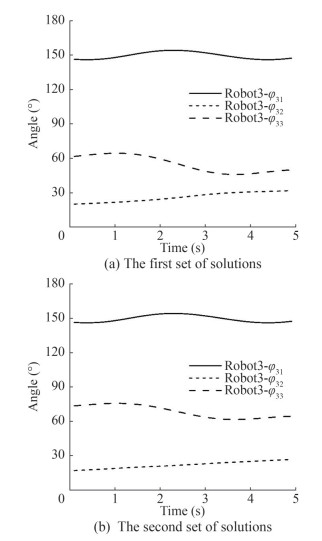 Figure 6 Joint angle curves of Robot 3
5.2 Stability simulation
The stability cone method is suitable for the mobile robot subject to inertial load and any external force, considering many factors affecting stability. It is also suitable for complex environments. The specific solution steps are as follows:
1) Combining the kinematic and dynamic equations of the towing system, the end position of the towing robot, the rope tension, and the joint angle of the robot are solved.
2) According to the structure parameters and spatial layout of the towing system, the barycenter position of the floating robot (the stability cone vertex) can be obtained.
3) Force analysis may be conducted on the towing system to calculate the equivalent force on the barycenter of the floating robot.
4) The contact position of the floating base and the fluid (stability cone corner point) and the axis of overturning are determined.
5) The angle between the effective force and the overturning axis normal or overturning corner point is calculated to obtain the overturning performance index, which judges the stability of the towing system.
The system was analyzed using numerical simulations to verify the rationality of the aforementioned stability criterion. The three floating robots towed the same load through the ropes, making the load distributed evenly according to the carrying capacity of each robot. The load distributed principle of internal force of 0 at the barycenter was adopted to make the load do the vertical upward movement. The overturning stability of the towing robot in two configurations (two sets of joint angles) was analyzed using the stability cone method. During the simulation, when the floating robot capsized, the corresponding overturning index became infinite. Therefore, the overturning index boundary was proposed to visually analyze the stability degree. Figures 7–9 show the overturning performance index curves of the robots under dynamic force conditions. The red curves in the figures show the operating conditions outside the stability cone, whereas the green curves are the operating conditions inside the stability cone.
 Figure 7 Overturning index of Robot 1
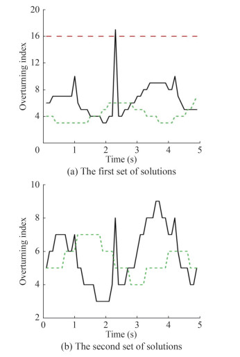 Figure 8 Overturning index of Robot 2
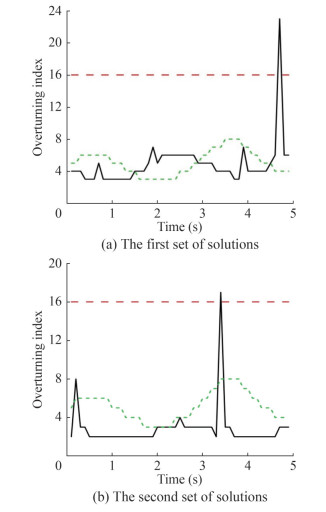 Figure 9 Overturning index of Robot 3
Figures 7–9 show that the overturning stability index of the two configurations of Robot 1 and configuration (a) of Robot 2 did not exceed the overturning boundary, implying good stability. The overturning stability index of configuration (b) of Robot 2 and both configurations of Robot 3 crossed the overturning boundary line once, so Robots 2 and 3 overturned when towing. Although the method of evaluating stability did not provide an instantaneous stability margin, the satisfaction degree could be analyzed to determine whether the towing system is stable.
According to the above analysis, the results show that the whole towing system overturns when the floating robot tows a large load and the robot's forward extension is too large during the towing process. By comparing the overturning stability index and the overturning boundary line, the operator can use more appropriate techniques to conduct salvage operations at sea. For example, the towing load can move close to the robot and move the floating robot forward or backward. To sum up, when encountering a complex towing environment and tasks, the suitable configuration of the floating robot can be used to increase the safety of the towing. In reality, in addition to analyzing the stability of the towing system, the operability and comprehensive ability of the floating robot are studied.
6 Conclusion
This paper combined industrial robots and towing equipment to propose a new floating multirobot coordinated towing system. First, the spatial configuration of the floating multirobot coordinated towing system was described, and the kinematic and dynamic models of the floating robot and rope-driven parallel towing system were established. On the basis of the simulation results of the kinematics, the dynamic stability of the floating robot was analyzed using the stability cone method, considering the three factors of the edge overturning, corner point overturning, and minimum overturning energy of the floating robot. The overturning index curves of the floating robot in different configurations were obtained, and the stability of each stage was discussed during the towing. Simulation experiments provided a reference for the practical application of the floating multirobot coordinated towing system, and the stability of the towing system could be improved by changing the configuration of the floating robot.
Competing interest The authors have no competing interests to declare that are relevant to the content of this article. -
Figure 1 Structure of the multirobot towing system
Figure 2 Diagram of the towing system
Figure 3 Projection diagram of the towing system in the plane
Figure 4 Joint angle curves of Robot 1
Figure 5 Joint angle curves of Robot 2
Figure 6 Joint angle curves of Robot 3
Figure 7 Overturning index of Robot 1
Figure 8 Overturning index of Robot 2
Figure 9 Overturning index of Robot 3
Table 1 Structural parameters
Parameter Value Mass of object m (kg) 1.6 × 10³ Mass of base M (kg) 3.2 × 10³ Lengtd of rope Li (m) 30 Size of link 1 a1 (m) 10 Size of link 2 a2 (m) 15 Size of link 3 a3 (m) 15 Table 2 Initial positions of the towing robot
Position X(m) Y(m) Z(m) O1 0 35 0 O2 -17.5$\sqrt{3}$ -17.5 0 O3 17.5$\sqrt{3}$ - 17.5 0 A1 0 20 30 A2 -10$\sqrt{3}$ -10 30 A3 10$\sqrt{3}$ -10 30 -
Chandrasekaran S, Jain A (2002) Triangular configuration tension leg platform behavior under random sea wave loads. Ocean Engineering 29(15): 1895–1928. DOI: 10.1016/s0029-8018(01)00111-1 Choi JH, Grizzle JW (2005) Planar bipedal walking with foot rotation. American Control Conference 2005 IEEE, 4909–4916. DOI: 10.1109/acc.2005.1470773 Graham R, Yao F (1983) Finding the convex hull of a simple polygon. Journal of Algorithms 4(4): 324–331. DOI: 10.1016/0167-8655(82)90016-2 Hatano M, Obara H (2005) Eeperiments of stability evaluation for mobile manipulators using criteria based on reaction and stabilization motion. Sice Conference 2005 IEEE 71: 928–935. DOI: 10.1299/kikaic.71.928 Horoub M, Hawwa M (2018) Influence of ropes layout on the dynamic workspace of a six-DOF parallel marine manipulator. Mechanism and Multi-robot Theory 129: 191–201. DOI: 10.1016/j.mechmachtheory.2018.07.022 Jia N, Yang SG, Qian S (2015) Design and feasibility study of connecting device for cooperation of multiple mobile cranes. Machinery Design & Manufacture 1(7): 200–203. (in Chinese) DOI: 10.19356/j.cnki.1001-3997.2015.07.055 Jia XL, Yang YS (1999) Mathematical model of ship motion. Dalian Maritime University Press, Dalian. (in Chinese) Jiang Q, Kumar V (2012) Determination and stability analysis of equilibrium configurations of objects suspended from multiple aerial robots. Journal of Mechanisms & Robotics 4(2): 510–521. DOI: 10.1115/1.4005588 Jiang Q, Kumar V (2013) The inverse kinematics of cooperative transport with multiple aerial robots. IEEE Transactions on Robotics 29(1): 136–145. DOI: 10.1109/tro.2012.2218991 John JC, Yun C, Wang W (2018) Introduction to robotics. Machinery Industry Press, Beijing Liu JG, Wang YC, Li B (2006) Simulation analysis of the overturning stability of the deformed robot. Journal of System Simulation 18(2): 409–415. (in Chinese) Long LB, Qing QX, Wen GL (2010) Simulation analysis of the soft landing stability of the lander based on ADAMS. Journal of Engineering Design 17(5): 334–338. (in Chinese) Papadopoulos EG, Rey DA (1996) A new measure of tip-over stability margin for mobile manipulators. Proceedings of the IEEE International Conference on Robotics and Automation, Minneapolis: 3111–3116. DOI: 10.1109/robot.1996.509185 Pott A (2018) The rope-driven parallel robots theory and application. Springer Rey DA, Papadopoulos EG (1997) Online automatic tip-over prevention for mobile manipulators. IEEE/RSJ International Conference on Intelligent Robots & Systems. IEEE, 310–315 Schellin T E, Jiang T, Sharma SD (1991) Crane ship response to wave groups. Journal of Offshore Mechanics and Arctic Engineering 113(3): 211–218. DOI: 10.1115/1.2919922 Su C, Zhao XT, Yan ZZ (2023) Load stability analysis of a floating multi-robot coordinated towing system. Journal of Shanghai Jiao Tong University (Science). DOI: 10.1007/s12204-023-2634-7 Su C, Zhao XT, Yan ZZ (2024) Workspace analysis of a floating multi-robot coordinated lifting system. Journal of Marine Science and Application 23: 148–159. DOI: 10.1007/s11804-024-00389-3 Zhao XT, Zhao ZG, Su C (2023a) Simulation of floating multi-robot coordinated towing system. Journal of Machine Design 40(6): 16–22. (in Chinese) DOI: 10.13841/j.cnki.jxsj.2023.06.010 Zhao ZG, Lu TS (2007) Equilibrium computation of close-coupling multiple-helicopters in hover condition. Journal of System Simulation 19(1): 153–155. (in Chinese) Zhao ZG, Lu TS (2013) Simulation on kinematics and stability of multi-helicopters hoist system. Journal of System Simulation 25(4): 790–794. (in Chinese) DOI: 10.16182/j.cnki.joss.2013.04.010 Zhao ZG, Zhao XT, Su C (2023b) Dynamic modeling and simulation of a floating multi-robot coordinated towing system. Journal of Harbin Engineering University 44(10): 1825–1831. (in Chinese)
