
Flow-Induced Transverse Vibration of Three Equal-Diameter Cylinders in an Equilateral Triangle Using the Immersed Boundary–Lattice Boltzmann Flux Solver
https://doi.org/10.1007/s11804-024-00461-y
-
Abstract
To explore the relationship between dynamic characteristics and wake patterns, numerical simulations were conducted on three equal-diameter cylinders arranged in an equilateral triangle. The simulations varied reduced velocities and gap spacing to observe flow-induced vibrations (FIVs). The immersed boundary–lattice Boltzmann flux solver (IB – LBFS) was applied as a numerical solution method, allowing for straightforward application on a simple Cartesian mesh. The accuracy and rationality of this method have been verified through comparisons with previous numerical results, including studies on flow past three stationary circular cylinders arranged in a similar pattern and vortex-induced vibrations of a single cylinder across different reduced velocities. When examining the FIVs of three cylinders, numerical simulations were carried out across a range of reduced velocities (3.0 ≤ Ur ≤ 13.0) and gap spacing (L = 3D, 4D, and 5D). The observed vibration response included several regimes: the desynchronization regime, the initial branch, and the lower branch. Notably, the transverse amplitude peaked, and a double vortex street formed in the wake when the reduced velocity reached the lower branch. This arrangement of three cylinders proved advantageous for energy capture as the upstream cylinder's vibration response mirrored that of an isolated cylinder, while the response of each downstream cylinder was significantly enhanced. Compared to a single cylinder, the vibration and flow characteristics of this system are markedly more complex. The maximum transverse amplitudes of the downstream cylinders are nearly identical and exceed those observed in a single-cylinder set-up. Depending on the gap spacing, the flow pattern varied: it was in-phase for L = 3D, antiphase for L = 4D, and exhibited vortex shedding for L = 5D. The wake configuration mainly featured double vortex streets for L = 3D and evolved into two pairs of double vortex streets for L = 5D. Consequently, it well illustrates the coupling mechanism that dynamics characteristics and wake vortex change with gap spacing and reduced velocities.Article Highlights● FIV of multiple cylinders can be simply solved by IBM-LBFS using Cartesian mesh.● Transverse vibration response of downstream two cylinders in an equilateral-triangular configuration can be enhanced at 3D ≤ L ≤ 5D.● Flow patterns of FIV in resonance region is similar to the state of flow past stationary equal-diameter cylinders in an equilateral triangle. -
1 Introduction
Flow-induced vibration (FIV), a key aspect of fluid– structure interaction (FSI) problems, has garnered widespread attention in both practical engineering and the complex physical mechanics of fluid dynamics over the past several decades (Han et al., 2019, Zhang et al., 2023). This phenomenon plays a crucial role in understanding how structures interact with fluid flows. FIV can lead to structural vibrations, fatigue, and even damage in various engineering applications (Chen and Wu, 2020; Rabiee et al., 2021), including aerospace (Vahdati et al., 2020), offshore structures (Wang et al., 2020), and heat exchanger tubes (Ji et al., 2020). As such, considerable research efforts have been directed toward employing technologies to mitigate these oscillations and minimize potential damage. Conversely, the vibration response also presents significant opportunities for self-sustaining energy systems and energy harvesting. The idea that vibration energy can be captured and repurposed is gaining traction (Mohanty et al., 2019), finding applications in micro aerial vehicles (Li et al., 2016) and cantilever-driven rotors (Tan et al., 2021). Particularly in ocean engineering, there is an increasing focus on utilizing FIV energy from multiple bluff bodies as a clean and renewable energy source (Chen et al., 2020a). However, the challenge lies in understanding the interaction coupling mechanism of FIV among multiple bluff bodies, whether for vibration control or energy harvesting, making it a vital area of study.
In recent years, naval and ocean engineering has seen a particular interest in the flow past arrayed offshore structures, often geometrically simplified to circular cylinders. This simplification addresses a range of structures, from subsea pipelines to spar platforms and energy harvesting devices. Extensive research has been dedicated to this area including comprehensive reviews and discussions (Bearman, 2011; Zhou and Alam, 2016; Wang et al., 2020). For a single cylinder, factors such as mass-damping, reduced velocity, and Reynolds number are analyzed for their impact on vortex-induced vibration (VIV) responses and flow characteristics (Wu and Wang, 2017). Meanwhile, studies on two cylinders have delved into diverse arrangements, including tandem, side-by-side, or staggered form, gap spacing and differences in diameter affect VIV, in addition to parameters considered for an isolated cylinder (Alam et al., 2018; Song et al., 2020).
The interference effects between multiple bluff bodies, particularly with three or more cylinders, present a highly complex scenario, closely linking the coupling of vibration responses and wake patterns (Fan et al., 2020; Xu et al., 2021). Chen et al. (2018) carried out the FIV of three tandem cylinders in the cross-flow direction at Re = 100, exploring reduced velocities ranging from 3 to 80. Their findings revealed that small gap spacing led to strong wake interference, exciting large-amplitude vibrations in the cylinders. Notably, even at high reduced velocities, significant vibration amplitudes were observed in the two downstream cylinders. Ma et al. (2019) experimentally investigated the FIV of three cylinders arranged in an equilateral triangle within a towing tank, aiming to elucidate their response characteristics. In a similar vein, Zhang et al. (2018) investigated VIV energy harvesting, focusing on optimizing power-to-volume density by arranging four staggered cylinders reasonably. Their findings indicated a consistent increase in average power-to-volume density as in-line spacing decreased, identifying three regions of multicylinder interference: synchronization, blocking/encouragement, and recovery. Luo and Zhang (2015) performed simulations on FIV involving four coupling-linked and springmounted cylinders in uniform currents. Their results demonstrated that both energy harvesting and power density experienced an initial increase with larger spacing ratios, followed by a plateau in energy harvesting and a decline in power density. These studies collectively underscore the incomplete understanding of FIV coupling mechanisms when dealing with configurations of more than two cylinders. The plethora of influencing factors, including flow conditions, geometric parameters, wake interference, and lay out form, make the systematic study of FIV in multiple circular cylinder systems a worthwhile endeavor. Among these configurations, the three cylinders with an equilateral triangle stands out as a fundamental unit in numerous engineering applications. Wang et al. (2013) numerically studied the FIV considering typical flow incidence angles. Their research revealed that vortex shedding frequencies, oscillation trajectories and response amplitudes were significantly influenced by the incidence angle. Similarly, Xu et al. (2014) investigated the FIV at two incidence angles, finding that simultaneous resonance could occur, with the inflow vibration aligning with that of cross-flow vibration for downstream two cylinders.
In this paper, we delve into the effects of the equilateral triangle configurations, gap spacing, and reduced velocities on flow and vibration characteristics. Previous research has shown that for three stationary equal-diameter cylinders arranged in an equilateral triangle configuration with a Reynolds number (Re) of 100, wake patterns vary significantly with gap spacing. Specifically, inphase wake are observed when the gap spacing is L = 3D (where D represents their diameter and L stands for the center-to-center spacing between two cylinders), antiphase patterns at L = 4D, and coshedding patterns at L = 5D, as documented by Yang et al. (2019). Another motivation behind this research is to uncover the relationship between the dynamic characteristics of free vibration and the wake patterns in a stationary state.
Numerical simulation stands as a powerful and convenient tool for addressing FIV problems. Selecting an appropriate numerical method is crucial for effectively solving fluid–structure interaction problems (Giannopoulou et al., 2019). Based on Kang (2010), fluid–structure coupling algorithms can be classified into three main approaches: the body conforming grid approach (Chen and Zha, 2010), the overset grid approach (Laborderie et al., 2018), and the non-body conforming grid approach (Favier et al., 2014). The body conforming approach faces challenges in mesh generation, while the overset grid approach struggles with conservation guarantees. Therefore, this paper employs the non-body conforming approach owing to its ability to conveniently handle moving boundaries. The immersed boundary (IB) method, which has garnered significant interest in recent years, is particularly highlighted. We utilize enforced IB method proposed by Wang et al. (2015) for solving FIV problems, ensuring adherence to the no-slip boundary condition. Lattice Boltzmann flux solver (LBFS) proposed by Shu et al. (2014) served as flow field solver. Finite volume method is applied to discretize the macroscopic incompressible governing equations in space. Moreover, flux solutions are reconstructed at the interface between two adjacent cell centers. The incorporation of multiple-relaxation– time model enhances computational accuracy and numerical stability (Luo et al., 2011; Favier et al., 2014; Haussmann et al., 2020). Consequently, a numerical method that combines the IB and multi-relaxation-time LBFS (Wu et al. 2017a) is applied to investigate vibrations in FIV cylinders.
In this paper, we aim to apply a simple fluid structure coupling method known as the IB – LBFS for conducting numerical simulations on the flow-induced transverse vibration of three equal-diameter cylinders arranged in an equilateral triangle. First, the reliability of this numerical method is established through simulations examining the flow past three stationary circular cylinders also arranged in an equilateral triangle, as well as the VIV of a single circular cylinder subjected to various reduced velocities. Subsequently, we extend our investigation to simulations that capture the FIV of three circular cylinders. These simulations are differentiated by varying gap spacings and reduced velocities, allowing us to explore how these parameters influence the system behavior. Through comparisons of vibration amplitudes, force coefficients, and flow characteristics, we delve into the effects of gap spacing and reduced velocities on both vibration and flow characteristics.
2 Mathematical model and numerical method
2.1 Governing equations and numerical method for fluid flow
For incompressible viscous fluids, the macroscopic Navier– Stokes equations based on the general IB method (Wang et al., 2015) can be expressed as follows:
$$ \frac{\partial \rho}{\partial t}+\nabla \cdot(\rho \boldsymbol{u})=0 $$ (1) $$ \frac{\partial}{\partial t}(\rho \boldsymbol{u})+\nabla \cdot(\rho \boldsymbol{u} \cdot \boldsymbol{u}+p \mathbf{I})=\nabla \cdot\left\{\mu\left[\nabla \boldsymbol{u}+(\nabla \boldsymbol{u})^{\mathrm{T}}\right]\right\}+\boldsymbol{F} $$ (2) where ρ, p, and μ represent fluid density, pressure, and dynamic viscosity coefficient, respectively. u stands for the velocity vector, and I denotes a unit tensor. The expression for pressure is given by p = ρcs2 where cs is the lattice sound speed based on the lattice model. F represents a restoring force given by the IB method. An implicit method, known as the boundary-condition–enforced IB method, is applied because it can precisely satisfy the no-slip boundary condition. The velocity correction of the Eulerian points is employed instead of the force source term. The procedure to solve the governing equations in two steps is summarized as follows:
1) The first step involves predicting the flow field without considering boundary effects. This includes calculating the intermediate velocity and density for the next calculation step. For the LBFS, the fluxes are established by the equilibrium distribution function. The expressions are as follows:
$$ \frac{\rho^{n+1}-\rho^n}{\Delta t}+\nabla \cdot\left(\sum\limits_{\alpha=0}^N \boldsymbol{e}_\alpha f_\alpha^{\mathrm{eq}}\right)=0 $$ (3) $$ \begin{gathered} \frac{\rho^{n+1} \boldsymbol{u}^*-\rho^n \boldsymbol{u}^n}{\Delta t} \\ +\nabla \cdot\left\{\sum\limits_{\alpha=0}^N\left(\boldsymbol{e}_\alpha\right)_\beta\left(\boldsymbol{e}_\alpha\right)_\gamma \boldsymbol{M}^{-1}\left[m_\alpha^{\mathrm{eq}}+\left(\mathbf{I}-\frac{1}{2} \boldsymbol{S}\right) m_a^{\mathrm{neq}}\right]\right\}=0 \end{gathered} $$ (4) where n is the calculation step and Δt represents the time step; e is the particle velocity; M is the transformation matrix; I is the unit matrix; S is a diagonal relaxation matrix; fα and feqα are the discrete density distribution function and equilibrium term, respectively; ma and mαeq stand for the distribution function and equilibrium term in the moment space, respectively.
2) The second step involves correcting the flow field velocity by employing the enforced IB method. The corrected velocity of the Eulerian points can be obtained by solving the matrix equation, which is established based on the velocities of the Lagrangian points. The velocities of these points must match the fluid velocities, ensuring that the solid wall boundary condition adheres to the no-slip principle. The restoring force (F) is defined as follows:
$$ \boldsymbol{F}=\frac{\rho^{n+1}\left(\boldsymbol{u}^{n+1}-\boldsymbol{u}^*\right)}{\Delta t} $$ (5) where un + 1 is the velocity after correction and u* is the intermediate velocity between two time steps.
2.2 The equations of motion for a cylinder
In the present study, the moving rigid body is assumed to be elastically mounted, allowing displacements by unsteady forces in the transverse direction in the Cartesian coordinate. The elastically mounted circular cylinder can be modeled by a simple mass–damper–spring system (Suzuki and Inamuro, 2011) as follows:
$$ \ddot{Y}+4 \pi f_r \zeta \dot{Y}+\left(2 \pi f_r\right)^2 Y=\frac{2 C_L}{\pi m_r} $$ (6) where Ÿ, Ẏ, and Y are the normalized acceleration, velocity and displacement of the rigid cylinder, respectively. fr is the reduced natural frequency of the system defined by fr = fn D/U, where fn, D, and U are the natural frequency of the cylinder, the cylinder diameter (the non-dimensional size), and the free-stream speed, respectively. The reduced velocity is defined as Ur = 1/fr. CL stands for the lift coefficient. The term ζ is the structural damping ratio. mr represents the non-dimensional mass of the body, which is defined by mr = 4 m/ (πρD2). With consideration of the inertial effects or the internal mass effects of the moving objects, a more precise expression is written as follows:
$$ \boldsymbol{F}=\left\{F_L, F_D\right\}=-\sum\limits_l \frac{\rho \Delta \boldsymbol{u}_B^l \Delta s^l}{\Delta t}+\rho V_B \frac{\mathrm{~d} U_B}{\mathrm{~d} t} $$ (7) where FL and FD represent the lift force and drag force, respectively. VB and UB are the volume and velocity of the rigid body. The fourth-order Runge–Kutta algorithm is employed to solve the motion equations for the rigid body.
2.3 Problem description
The study models the physical problem as FIV involving three equal-diameter cylinders arranged in an equilateral triangle within a rectangular computational domain, as shown in Figure 1. For the purposes of numerical analysis, the cylinders are sequentially numbered and referred to as cy1, cy2, and cy3, respectively. The diameter of each circular cylinder is denoted by D, while L represents the side length of the equilateral triangle or the spacing between any two adjacent cylinders. The dimensions of the entire computational domain are set to [−40D, 100D]×[−40D, 40D], featuring a non-uniform mesh. The dimensions of the specific rectangular region outlined by the red dotted line are [−(0.5L+1.5D), (0.5L+1.5D)]×[−(0.5L+1.5D), (0.5L+ 1.5D)], and a uniform Cartesian mesh is employed for detailed analysis. The inlet boundary condition introduces a uniform incoming flow with velocities ux = U∞ and uy = 0. The outlet boundary condition enforces ∂ux /∂x = 0 and ∂uy/∂x = 0, while the top and bottom boundary conditions apply ∂ux /∂x = 0 and uy = 0, respectively. The solid boundary of the cylinders is represented by uniformly distributed Lagrangian points.
 Figure 1 The computational domain and boundary conditions for flow-induced transverse vibration of three equal-diameter cylinders in an equilateral triangle
A detailed view of the computational mesh is displayed in Figure 2, showcasing both the overall computational mesh in Figure 2(a) and a close-up of the uniform mesh, with every 8 points displayed in Figure 2(b). The ratio of Lagrangian to Eulerian points is maintained between π/2 and π to ensure adherence to the no-slip boundary conditions and facilitate velocity correction between adjacent Lagrange and Euler points. Consequently, for computational efficiency and stability, as recommended by Wang et al. (2015), each cylinder is assigned 150 Lagrangian points, and the uniform mesh area features 80 Eulerian points per diameter. The analysis focuses on transverse vibration, setting the structural damping ratio to 0 to capture the maximum amplitude of transverse vibration. The non-dimensional mass of each cylinder is equivalent to 10.
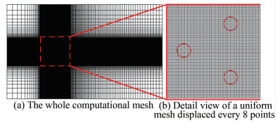 Figure 2 The computational mesh for three equal-diameter cylinders
From Yang et al. (2019), it was observed that for the flow past three stationary equal-diameter cylinders in an equilateral triangle with a Reynolds number of Re = 100, the wake patterns vary according to the gap spacing: in-phase at L = 3D, antiphase at L = 4D, and coshedding at L = 5D. To further investigate the connection between the dynamic characteristics of free vibration and the wake patterns in a stationary state, numerical simulations were conducted. These simulations explored flow-induced transverse vibration of three equal-diameter cylinders in an equilateral triangle across different gap spacings (L = 3D, 4D, and 5D) and a range of reduced velocities (3.0 ≤ Ur ≤ 13.0) at Re = 100.
3 Numerical simulations and discussions
3.1 Numerical validations
In this section, the numerical method is validated through simulations of flow past three stationary circular cylinders in an equilateral triangle and VIV of a circular cylinder at various reduced velocities.
For flow past three stationary equal-diameter cylinders, both the wake patterns and force coefficients are discussed. The wake pattern is in-phase when the gap spacing L=3D, as shown in Figure 3(a), antiphase at L=4D, as shown in Figure 3(b), and a coshedding and in-phase pattern at L=5D, as shown in Figure 3(c). From Figure 3, it is evident that there is insufficient space for the wake development of cy1 at L=3D and 4D, resulting in the wake of cy1, with little fluctuations, passing through the gap between cy2 and cy3. The wake patterns are consistent with the analysis results by Yang et al. (2019) at different gap spacings.
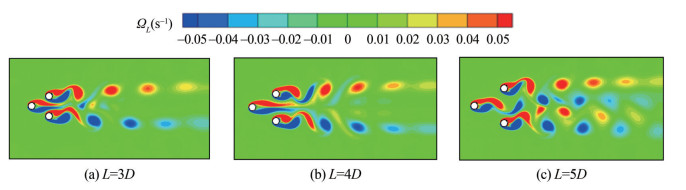 Figure 3 Instantaneous vorticity contours for three equal-diameter cylinders for different gap spacings
Additionally, the temporal evolutions of drag and lift coefficients for different gap spacings are presented in Figure 4. Notably, there is almost no phase difference in the lift coefficients between cy2 and cy3 at L=3D and L=5D, as shown in Figure 4(a) and (e). A 180° phase difference is observed at L=4D, as shown in Figure 4(c). Moreover, the phase difference in the drag coefficient is the opposite of that of the lift coefficient for the same gap spacing, as demonstrated by comparing Figure 4(a) and (b), Figure 4(c) and (d), and Figure 4(e) and (f). This indicates that the wake pattern correlates with the phase difference of the force coefficients. Furthermore, the numerical results, including the mean value of the drag coefficient and the root mean square (rms) value of the lift coefficient, closely match those reported by Yang et al. (2019), as shown in Table 1. These analyses further prove that the numerical method is aptly suited for addressing the problem of flow past multiple bluff bodies and can effectively calculate forces and capture the wake dynamics within the flow field.
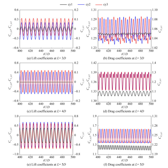 Figure 4 Time evolution patterns of drag and lift coefficients for different gap spacingsTable 1 Comparison of numerical results for flow past three stationary circular cylinders.
Gap spacing Results CD_mean CL_rms cy1 cy2 cy3 cy1 cy2 cy3 L=3D Yang et al. (2019) 1.032 1.229 1.229 0.018 0.182 0.182 Present results 1.053 1.267 1.267 0.018 0.199 0.199 L=4D Yang et al. (2019) 1.062 1.322 1.322 0.000 0.311 0.311 Present results 1.088 1.369 1.369 0.000 0.325 0.325 L=5D Yang et al. (2019) 1.163 1.384 1.399 0.198 0.471 0.441 Present results 1.211 1.451 1.456 0.217 0.464 0.456 For the study of VIV of a circular cylinder at various reduced velocities, we delve into the peak amplitude of transverse vibration along with the force coefficients, comparing these findings with existing numerical results. Figure 5 to Figure 7 reveal that the maximum transverse amplitudes, Strouhal number, and the rms values of the lift and drag coefficients align closely with the results obtained by Singh and Mittal (2005). Despite some minor discrepancies, likely owing to differences in numerical methods and computational models, the accuracy and validity of the numerical method are confirmed through this comparison.
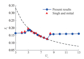 Figure 5 Variation in the Strouhal number with reduced velocity
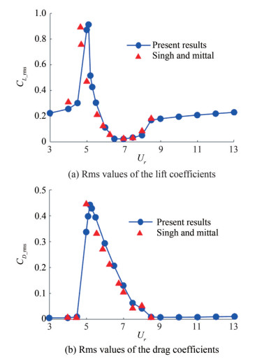 Figure 7 Variation in the rms values of the lift and drag coefficients with reduced velocity
An isolated cylinder enters the resonance region when the frequency of the shedding vortex approaches the natural frequency, as depicted by the black dashed line in Figure 5. This figure indicates that the lock-in regime for the isolated cylinder ranges from a reduced velocity Ur of 5.0 to 8.0 for the isolated cylinder. The variation in max transverse amplitude and the time evolutions of lift coefficients and transverse vibration displacement across different reduced velocities are shown in Figure 6. The vibration response is classified into several regimes: the desynchronization regime I (DSI, highlighted in light gray), the periodic initial branch (shown in green), the periodic lower branch (shown in white), the quasi-periodic lower branch (shown in purple), and the desynchronization regime II (shown in blue). It can be observed that the peak amplitude of the transverse vibration approaches 0.545D. Moreover, the evolution of lift coefficients and transverse vibration displacement transitions from inphase to antiphase with varying reduced vibrations.
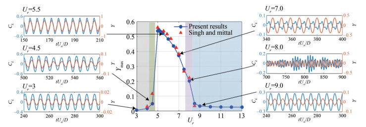 Figure 6 Variation in max transverse amplitudes and the time evolutions of lift coefficients and transverse vibration displacement with reduced velocity
As shown in Figure 8, instantaneous vorticity contours for isolated cylinders are presented across different regimes. The observed wake patterns mainly consist of a single vortex street in most regimes, transitioning to a double vortex street at the onset of the "lock-in" regime, notably at Ur= 5.5.
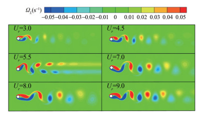 Figure 8 Instantaneous vorticity contours for isolated cylinders
3.2 Flow-induced vibration on three equal-diameter cylinders in an equilateral-triangular configuration
This section delves into the vibration characteristics, aerodynamics forces, and flow patterns associated with flow induced transverse vibration of three equal-diameter cylinders in an equilateral triangle at different gap spacings. The numerical results are then compared with those of an isolated circular cylinder.
3.2.1 Vibration characteristics
The variations in Strouhal numbers with reduced velocity for different gap spacings (L=3D, L=4D, and L=5D) are shown in Figure 9. For three equal-diameter cylinders arranged in an equilateral triangle, the shedding vortex frequencies remain consistent across all three cylinders. Figure 9 further details the variation in the Strouhal number with reduced velocity, marking the initiation and conclusion points of the lock-in phase, as well as delineating the lock-in regime's range. More specially, the lock-in regime is 5.0≤ Ur ≤7.5 for a single cylinder. For configurations with L/D= 3, the regime is 5.0 ≤ Ur ≤ 10; for L/D = 4, the regime is 5.0 ≤ Ur ≤8.5; and for L/D =5, the regime is 4.5 ≤Ur ≤8.5. Compared to an isolated cylinder, these findings suggest that the lock-in region's range broadens within an FIV system. Notably, the most extensive lock-in regions are observed for L/D =3, attributed to the heightened interaction among the three bluff bodies at smaller gap spacings.
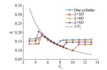 Figure 9 Variation in the Strouhal number with reduced velocity
Figure 10 illustrates the variations in the maximum and rms values of transverse amplitude with the reduced velocity at different gap spacings. When compared to an isolated cylinder, it is observed that the maximum transverse amplitude of cy1 closely mirrors that of a single VIV cylinder. However, the maximum transverse amplitudes of cy2 and cy3 are nearly identical and exceed that of a single cylinder. This indicates that the interaction among the three circular cylinders delays cy1's entry into the lock-in region while having a minimal effect on the starting point of the lock-in region for cy2 and cy3.
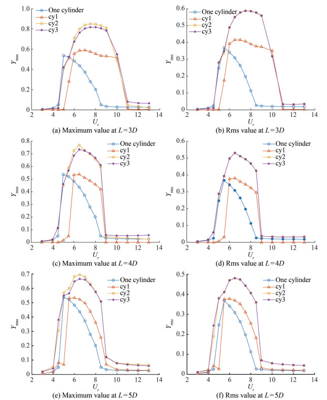 Figure 10 Variation in the maximum and rms values of the transverse amplitude with reduced velocity at different gap spacings
Figure 10(a) and (b) reveal that the vibration responses are strongly strengthened at L/D=3, and the "lock-in" region is broader compared to that of an isolated cylinder. This observation aligns with the variations seen in the Strouhal number. For L/D ratios of 4 and 5, the maximum and rms values of transverse amplitude for cy1, when considering reduced velocity, are nearly identical to those of an isolated VIV cylinder. Similar to the behavior observed in a VIV cylinder, the vibration response for the three-cylinder system can be classified into the desynchronization regime, IB, and lower branch. The rate of increase is given in Table 2, which indicates a decrease in the increase ratio as the gap spacing widens. For L/D=3, the maximum transverse amplitudes recorded are 0.590 (Ur = 7.0), 0.851 (Ur = 7.5), and 0.818 (Ur = 8.0) for cy1, cy2, and cy3, respectively. In addition, the increase ratios for these configurations are 9.87%, 58.47%, and 52.33%, respectively. These results suggest that a smaller gap spacing leads to the downstream cylinders being affected by the wake of the upstream cylinder, resulting in more intense vibration responses.
Table 2 Comparison of maximum amplitudes of transverse vibrationGap spacing Isolated cylinder Maximum amplitude cy1 Increase ratio (%) cy2 Increase ratio (%) cy3 Increase ratio (%) L/D = 3 0.537 (Ur = 5.0) 0.590 (Ur = 7.0) 9.87 0.851 (Ur = 7.5) 58.47 0.818 (Ur = 8.0) 52.33 L/D = 4 0.537 (Ur = 5.0) 0.539 (Ur = 6.5) 0.37 0.769 (Ur = 6.5) 43.20 0.735 (Ur = 6.5) 36.87 L/D = 5 0.537 (Ur = 5.0) 0.534 (Ur = 6.0) −0.56 0.695 (Ur = 6.5) 29.42 0.666 (Ur = 6.5) 24.02 3.2.2 Aerodynamics forces
As shown in Figure 11, the variation in the maximum value of lift coefficient for cy2 or cy3 with reduced velocity at different gap spacing is similar to that of an isolated cylinder. However, the lift coefficient of cy1 is greatly affected by the two downstream cylinders, resulting in its maximum value being lower than that of both cy2 and cy3. As Ur approaches the IB, there is a sharp increase in the lift coefficient, which mainly contributes to the increase in transverse amplitude. Once Ur enters the lower branch, the lift coefficient peaks before it first decreases and then experiences a slight increase. Figure 12 further illustrates that the variation in the mean value of the drag coefficient for cy2 and cy3, with reduced velocity at different gap spacings, is akin to that observed in an isolated cylinder. What'smore, the values for cy2 and cy3 are nearly identical. At the same Ur, the mean value of the drag coefficient for cy1 is found to be lower than that of the two downstream cylinders.
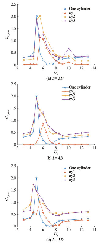 Figure 11 Variation of the maximum value of lift coefficient with the reduced velocity at different gap spacings
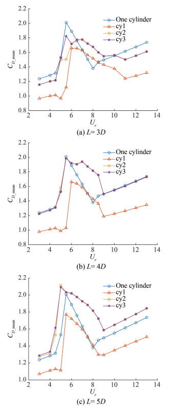 Figure 12 Variation in the mean value of drag coefficient with reduced velocity at different gap spacings
3.2.3 Flow characteristics
Instantaneous vorticity contours, illustrating FIV on three equal-diameter cylinders arranged in an equilateral triangle with varying reduced velocities at different gap spacings, are shown in Figures 13‒15. These figures allow for a detailed observation of the flow characteristics.
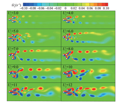 Figure 13 Instantaneous vorticity contours for three equal-diameter cylinders at L = 3D
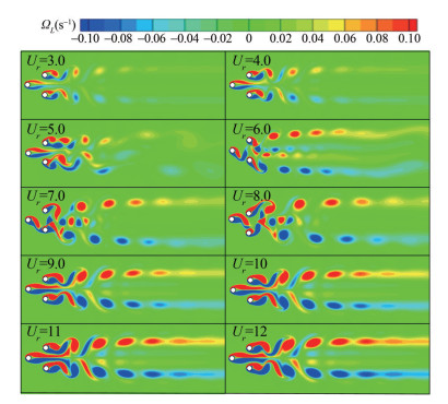 Figure 14 Instantaneous vorticity contours for three equaldiameter cylinders at L = 4D
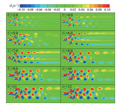 Figure 15 Instantaneous vorticity contours for three equaldiameter cylinders at L = 5D
From Figure 13, the flow characteristics of three FIV circular cylinders at L = 3D are as follows: 1) When 3.0 ≤ Ur ≤ 4.0, the shear layer separating from cy1 directly passes the gap spacing between cy2 and cy3, resulting in a clearly defined double vortex street wake pattern. This is similar to the in-phase pattern observed in flow past three stationary cylinders depicted in Figure 3(a). 2) When Ur= 5.5, the vibration response is enhanced, leading to an increase in transverse amplitude. Consequently, the wake of cy1 has little influence on cy2 and cy3, allowing for the shedding vortex from either cy2 or cy3 to occur independently. The wake behind the three-cylinder system becomes disordered. 3) When 6.0 ≤ Ur ≤ 9.0, the vibration responses fall within the lower branch, where the shear layer separating from cy1 curls up and attaches to either cy2 or cy3, creating a double vortex street wake pattern. 4) As the reduced velocity continues to increase, the vibration frequency diverges from the resonant frequency, causing the double vortex street phenomenon to gradually weaken. In this state, the wake becomes chaotic.
From Figure 14, flow characteristics of three FIV circular cylinders at L = 4D can be described as follows: 1) When 3.0 ≤ Ur ≤ 4.0, the shear layer separating from cy1 directly passes through the gap spacing between cy2 and cy3, resulting in a clearly defined pattern of double vortex streets. This pattern is reminiscent of the antiphase flow observed past three stationary cylinders depicted in Figure 3(b). 2) When Ur = 5.5, the vibration response is enhanced, and the trans verse amplitude is increased. The wake of cy1 goes through the gap spacing, leading to a disordered wake behind the three-cylinder system. 3) When 6.0 ≤ Ur ≤ 8.0, the vibration responses are found within the lower branch. Here, the shear layer separating from cy1 curls up and is shed from either cy2 or cy3, creating a wake pattern characterized by two pairs of double vortex streets. 4) As the reduced velocity continues to rise, the vibration frequency diverges from the resonant frequency, causing the distinct phenomenon of two pairs of double vortex streets to gradually weaken.
Figure 15 demonstrates that, at L = 5D, there is sufficient space for the shear layer separating from the three circular cylinders. The shedding vortex from cy1 either attaches to the downstream cylinder and sheds from the downstream column or navigates the gap spacing between cy2 and cy3. This results in a distinct wake pattern characterized by two pairs of double vortex streets within the lock-in region.
4 Conclusion
Numerical simulation results have been presented, focusing on FIV across three equal-diameter cylinders arranged in an equilateral triangle at varying reduced velocities and different gap spacings. A sophisticated numerical method that combines the IB method with the multi–relaxation–time LBFS has been applied and validated for flow passing three stationary circular cylinders and VIV of a circular cylinder at various reduced velocities.
The study delves into FIV on three equal-diameter cylinders, conducting numerical simulations over a range of reduced velocities (3.0 ≤ Ur ≤ 13.0) and gap spacings (L = 3D, 4D, and 5D). The vibration response encompasses the desynchronization regime, IB, and lower branch, aligning with the behavior observed in isolated VIV problems. Notably, the lock-in region is expanded in the system of three cylinders, especially for L = 3D. This configuration proves advantageous for energy harvesting as the vibration response of the upstream cylinder mirrors that of an isolated VIV cylinder, while the response of each downstream cylinder is amplified. This underscores the efficacy of multiple bluff body systems in energy harvesting applications, given their complex vibration and flow characteristics compared to those of a single cylinder. Furthermore, the maximum transverse amplitudes of downstream cylinders are consistently higher than those of a single cylinder. Specifically, for L = 3D, the flow pattern is in-phase with a double vortex street wake within the lock-in region. At L = 4D, the flow pattern shifts to antiphase, featuring two pairs of double vortex streets as the bluff body enters the lock-in region. Ultimately, for L = 5D, the flow pattern exhibits shedding vortices, with the wake mainly comprising two pairs of double vortex streets.
Competing interest The authors have no competing interests to declare that are relevant to the content of this article. -
Figure 1 The computational domain and boundary conditions for flow-induced transverse vibration of three equal-diameter cylinders in an equilateral triangle
Figure 2 The computational mesh for three equal-diameter cylinders
Figure 3 Instantaneous vorticity contours for three equal-diameter cylinders for different gap spacings
Figure 4 Time evolution patterns of drag and lift coefficients for different gap spacings
Figure 5 Variation in the Strouhal number with reduced velocity
Figure 7 Variation in the rms values of the lift and drag coefficients with reduced velocity
Figure 6 Variation in max transverse amplitudes and the time evolutions of lift coefficients and transverse vibration displacement with reduced velocity
Figure 8 Instantaneous vorticity contours for isolated cylinders
Figure 9 Variation in the Strouhal number with reduced velocity
Figure 10 Variation in the maximum and rms values of the transverse amplitude with reduced velocity at different gap spacings
Figure 11 Variation of the maximum value of lift coefficient with the reduced velocity at different gap spacings
Figure 12 Variation in the mean value of drag coefficient with reduced velocity at different gap spacings
Figure 13 Instantaneous vorticity contours for three equal-diameter cylinders at L = 3D
Figure 14 Instantaneous vorticity contours for three equaldiameter cylinders at L = 4D
Figure 15 Instantaneous vorticity contours for three equaldiameter cylinders at L = 5D
Table 1 Comparison of numerical results for flow past three stationary circular cylinders.
Gap spacing Results CD_mean CL_rms cy1 cy2 cy3 cy1 cy2 cy3 L=3D Yang et al. (2019) 1.032 1.229 1.229 0.018 0.182 0.182 Present results 1.053 1.267 1.267 0.018 0.199 0.199 L=4D Yang et al. (2019) 1.062 1.322 1.322 0.000 0.311 0.311 Present results 1.088 1.369 1.369 0.000 0.325 0.325 L=5D Yang et al. (2019) 1.163 1.384 1.399 0.198 0.471 0.441 Present results 1.211 1.451 1.456 0.217 0.464 0.456 Table 2 Comparison of maximum amplitudes of transverse vibration
Gap spacing Isolated cylinder Maximum amplitude cy1 Increase ratio (%) cy2 Increase ratio (%) cy3 Increase ratio (%) L/D = 3 0.537 (Ur = 5.0) 0.590 (Ur = 7.0) 9.87 0.851 (Ur = 7.5) 58.47 0.818 (Ur = 8.0) 52.33 L/D = 4 0.537 (Ur = 5.0) 0.539 (Ur = 6.5) 0.37 0.769 (Ur = 6.5) 43.20 0.735 (Ur = 6.5) 36.87 L/D = 5 0.537 (Ur = 5.0) 0.534 (Ur = 6.0) −0.56 0.695 (Ur = 6.5) 29.42 0.666 (Ur = 6.5) 24.02 -
Alam MM, Elhimer M, Wang L, Jacono DL, Wong CW (2018) Vortex shedding from tandem cylinders. Experiments in Fluids 59(3): 60. https://doi.org/10.1007/s00348-018-2501-8 Bearman P (2011) Circular cylinder wakes and vortex-induced vibrations. Journal of Fluids and Structures 27(5–6): 648–658. https://doi.org/10.1016/j.jfluidstructs.2011.03.021 Chen LF, Wu GX (2020) Flow-induced transverse vibration of a circular cylinder close to a plane wall at small gap ratios. Applied Ocean Research 103: 102344. https://doi.org/10.1016/j.apor.2020.102344 Chen W, Ji CN, Williams J, Xu D, Yang LH, Cui YT (2018) Vortex-induced vibrations of three tandem cylinders in laminar cross-flow: vibration response and galloping mechanism. Journal of Fluids and Structures 78: 215–238. https://doi.org/10.1016/j.jfluidstructs.2017.12.017 Chen XY, Zha GC (2010) Fully coupled fluid-structural interaction in a hybrid Cartesian-body fitted grid system. Computational Mechanics 46 (1): 3–16. https://doi.org/10.1007/s00466-009-0421-4 Chen Z, Alam MM, Qin B, Zhou Y (2020) Energy harvesting from and vibration response of different diameter cylinders. Applied Energy 278: 115737. https://doi.org/10.1016/j.apenergy.2020.115737 Fan X, Wang Z, Chen X, Wang Y, Tan W (2020) Experimental investigation on flow-induced vibration of flexible multi cylinders in atmospheric boundary layer. International Journal of Mechanical Sciences 183: 105815. https://doi.org/10.1016/j.ijmecsci.2020.105815 Favier J, Revell A, Pinelli AA (2014) Lattice Boltzmann-immersed boundary method to simulate the fluid interaction with moving and slender flexible objects. Journal of Computational Physics 261: 154–161. https://doi.org/10.1016/j.jcp.2013.12.052 Giannopoulou O, Colagrossi A, Di Mascioc A, Mascia C (2019) Chorin's approaches revisited: vortex particle method vs finite volume method. Engineering Analysis with Boundary Elements 106: 371–388. https://doi.org/10.1016/j.enganabound.2019.05.026. Han X, Lin W, Qiu A, Feng Z, Wu J, Tang Y, Zhao C (2019) Understanding vortex-induced vibration characteristics of a long flexible marine riser by a bidirectional fluid-structure coupling method. Journal of Marine Science and Technology 25: 620–639. https://doi.org/10.1007/s00773-019-00663-y Haussmann M, Hafen N, Raichle F, Trunk R, Krause, MJ (2020) Galilean invariance study on different lattice boltzmann fluid-solid interface approaches for vortex-induced vibrations. Computers & Mathematics with Applications 80(5): 671–691. https://doi.org/10.1016/j.camwa.2020.04.022 Ji J, Chen W, Gao R, Liu B, Zhang J (2020) Research on vibration and heat transfer in heat exchanger with vortex generator. Journal of Thermophysics and Heat Transfer 6: 1–7. https://doi.org/10.2514/1.T6081 Kang SK (2010) Immersed boundary methods in the lattice Boltzmann equation for flow simulation. PhD thesis, Texas A & M University, Texas Laborderie JD, Duchaine F, Gicquel L, Vermorel O, Wang G, Moreau S (2018) Numerical analysis of a high-order unstructured overset grid method for compressible les of turbomachinery. Journal of Computational Physics 363: 371–398. https://doi.org/10.1016/j.jcp.2018.02.045 Li D, Wu Y, Ronch AD, Xiang J (2016) Energy harvesting by means of flow-induced vibrations on aerospace vehicles. Progress in Aerospace Sciences 86: 28–62. https://doi.org/10.1016/j.paerosci.2016.08.001 Luo LS, Liao W, Chen X, Peng Y, Zhang W (2011) Numerics of the lattice Boltzmann method: effects of collision models on the lattice Boltzmann simulations. Physical review E 83(5): 056710. https://doi.org/10.1103/PhysRevE.83.056710 Luo ZM, Zhang LX (2015) Force characteristics and hydrokinetic energy harvesting for VIV of four coupling-linked cylinders. Journal of Vibration and Shock 34(17): 25–29. https://doi.org/10.13465/j.cnki.jvs.2015.17.005 Ma YX, Xu WH, Liu B (2019) Dynamic response of three long flexible cylinders subjected to flow-induced vibration (FIV) in an equilateral-triangular configuration. Ocean Engineering 183: 187–207. https://doi.org/10.1016/j.oceaneng.2019.04.096 Mohanty A, Parida S, Behera RK, Roy T (2019) Vibration energy harvesting: A review. Journal of Advanced Dielectrics 9(4): 1–17. https://doi.org/10.1142/S2010135X19300019 Rabiee AH, Barzan MR, Mohammadebrahim A (2021) Flow-induced vibration suppression of elastic square cylinder using windward-suction-leeward-blowing approach. Applied Ocean Research 109: 102552. https://doi.org/10.1016/j.apor.2021.102552 Shu C, Wang Y, Teo CJ, Wu J (2014) Development of lattice Boltzmann flux solver for simulation of incompressible flows. Advances in Applied Mathematics and Mechanics 6(4): 436–460. https://doi.org/10.4208/aamm.2014.4.s2 Singh SP, Mittal S (2005) Vortex-induced oscillations at low Reynolds numbers: hysteresis and vortex-shedding modes. Journal of Fluids and Structures 20(8): 1085–1104. https://doi.org/10.1016/j.jfluidstructs.2005.05.011 Song H, Huang W, Chang S (2020) Empirical model for wake induced vibrations frequency response of cylinder with low mass ratio. Ocean Engineering 195: 106746. https://doi.org/10.1016/j.oceaneng.2019.106746 Suzuki K, Inamuro T (2011) Effect of internal mass in the simulation of a moving body by the immersed boundary method. Computers and Fluids 49(1): 173–187. https://doi.org/10.1016/j.compfluid.2011.05.011 Tan Q, Fan K, Guo J, Wen T, Zhou S (2021) A cantilever-driven rotor for efficient vibration energy harvesting. Energy 235: 121326. https://doi.org/10.1016/j.energy.2021.121326 Vahdati M, Lee KB, Sureshkumar P (2020) A review of computational aeroelasticity of civil fan blades. International Journal of Gas Turbine 11(4): 22–35. https://doi.org/10.38036/jgpp.11.4_22 Wang JS, Fan D, Lin K (2020) A review on flow-induced vibration of offshore circular cylinders. Journal of Hydrodynamics 32(5): 415–440. https://doi.org/10.1007/s42241-020-0032-2 Wang H, Yu G, Yang W (2013) Numerical study of vortex-induced vibrations of three circular cylinders in equilateral-triangle arrangement. Advances in Mechanical Engineering 5: 1–14. https://doi.org/10.1155/2013/287923 Wang Y, Shu C, Teo CJ, Wu J (2015) An immersed boundary-lattice Boltzmann flux solver and its applications to fluid-structure interaction problems. Journal of Fluids and Structures 54: 440–465. https://doi.org/10.1016/j.jfluidstructs.2014.12.003 Wu W, Wang J (2017) Numerical simulation of VIV for a circular cylinder with a downstream control rod at low Reynolds number. European Journal of Mechanics-B/Fluids 68: 153–166. https://doi.org/10.1016/j.euromechflu.2017.12.005 Wu XD, Chen F, Liu HP (2017) Combined immersed boundary method and MRT lattice Boltzmann flux solver for numerical simulations of incompressible flows. Applied Mathematics and Mechanics 38(12): 1679–1696. https://doi.org/10.1007/s10483-017-2290-7 Xu F, Xiao Y, Liu H, Ou J (2014) Numerical study on vortex-induced vibration of three cylinders in equilateral-triangular arrangements. Proceedings of the 2nd Symposium on Fluid-Structure-Sound Interactions and Control, 391–398. https://doi.org/10.1007/978-3-642-40371-2_56 Xu W, Zhang S, Ma Y, Liu B (2021) Fluid forces acting on three and four long side-by-side flexible cylinders undergoing flow-induced vibration (FIV). Marine Structures 75: 102877. https://doi.org/10.1016/j.marstruc.2020.102877 Yang X, Ji C, Chen W, Zhang Z (2019) Wake patterns and hydrodynamic forces of flow around circular cylinders in an equilateral triangular arrangement. Journal of Hydrodynamics Ser. A 34(1): 69–76. https://doi.org/10.16076/j.cnki.cjhd.2019.01.009 Zhang AM, Li SM, Pu C, Li Shuai, Liu YL (2023) A unified theory for bubble dynamics. Physics of Fluids 35: 033323. https://doi.org/10.1063/5.0145415 Zhang B, Mao Z, Song B, Tian W, Ding W (2018) Numerical investigation on VIV energy harvesting of four cylinders in close staggered formation. Ocean Engineering 165: 55–68. https://doi.org/10.1016/j.oceaneng.2018.07.042 Zhou Y, Alam MM (2016) Wake of two interacting circular cylinders: a review. International Journal of Heat & Fluid Flow 62: 510–537. https://doi.org/10.1016/j.ijheatfluidflow.2016.08.008
