
Experimental Investigation of a Body Water Entry with a Water Jet Cavitator
https://doi.org/10.1007/s11804-024-00474-7
-
Abstract
This paper reports an experimental investigation on the flow of a water entry cavity formed with a water jet cavitator. To investigate the formation characteristics, systematic water entry experiments were conducted in a water tank under different water jet rates, entry velocities, entry angles, and nozzle diameters. The formation mechanism of the water entry cavity was also analyzed. Results indicate that before the model impacts the water surface for water entry with a water jet cavitator, a gas bubble is created, and its width increases as the model approaches the water surface. Moreover, the length of the water jet gradually reduces to zero due to the increase in the static pressure of the water. The formation of the cavity is directly correlated with the location of the stagnation point moving downstream from the far field of the water jet to the exit of the water jet nozzle with the increasing entry depth. The dominant parameter is the momentum ratio of the water jet and quiescent water.-
Keywords:
- Water entry ·
- Cavitation flow ·
- Water jet
Article Highlights● To investigate the formation characteristics of the water entry cavitation flow with a water jet cavitator, systematic water entry experiments were conducted in a water tank under different experimental conditions.● A gas bubble is created before the model impacts the water surface for water entry with a water jet cavitator. The width of the gas bubble increases as the model approaches the water surface before the model impacts the water surface.● The formation of the water entry cavitation flow with a water jet cavitator is directly correlated with the location of the flow stagnation moving downstream from the far field of the water jet to the exit of the water jet nozzle with increasing entry depth. -
1 Introduction
Vehicle water entry refers to a vehicle moving from air to water, penetrating the air-water interface under different entry conditions. In this process, the complex and variable multiphase flow, hydrodynamic force, and vehicle trajectory interact, depending on the water entry conditions, such as impact speed or ambient pressure (Lee et al., 1997). May (1975) and Truscott and Techet (2009) reported that during high-speed water entry, the substantial impact force exerted on the vehicle can detrimentally affect the vehicle structure, the instruments inside the vehicle, and the ballistic trajectory of the vehicle. Some approaches have been proposed and implemented to mitigate such impact. In particular, Kimerer (2012) used a drogue device and a nose cover to passively absorb the impact energy of vehicle high-speed water entry. However, such a design significantly limits the penetration capability of the vehicle. The proposed method of water entry with a liquid jet cavitator allows the entire vehicle to be completely enclosed within a cavity, potentially avoiding the detrimental impact on the vehicle structure through the liquid jet without extra mechanical components and achieving sufficient penetration (Jiang et al., 2017, 2018b; Jiang et al., 2018a). The benefits of air cavity enclosures have been observed in works on low-speed water entry problems. For example, Truscott et al. (2012) found that a cavity created by air entrainment and formed around an object greatly reduces unsteady forces generated due to vortex shedding. Jiang et al. (2023a) experimentally investigated a method for reducing the impact force of water entry that uses a gas jet to impinge on the liquid surface before the object entry and found that the maximum reduction in impact acceleration can reach nearly 90% with a 10% reduction in entry velocity relative to the impact without gas jet.
In this study, we experimentally investigated a new formation mechanism for water entry supercavitation, namely, water entry supercavitation with a water jet cavitator, as a potential method to reduce impact load during the high-speed water entry of large objects. In water entry with a water jet cavitator, the water nozzle installed at the front of the object serves as the cavitator with air entrainment to form a supercavity. Through this mechanism, the supercavity can enclose the entire object because it penetrates the air-water interface during water entry, avoiding direct contact between the object and the surrounding fluid medium similar to that in gas jet-assisted water entry for impact reduction.
This work is relevant to previous research on the flow mechanism of ventilation supercavitation with a gas jet cavitator (Jiang et al., 2017, 2018b; Jiang et al., 2018a; Jiang et al., 2023a), a liquid jet impinging on a liquid surface with a wide range of applications in industrial and chemical engineering (Roy and Kumar, 2018; Muñoz-Esparza et al., 2012), drop formation in a falling stream of liquid (Grubelnik and Marhl, 2005), bubbly flow (Zhang et al., 2023), and cavitation multiphase flow (Liu et al., 2023; Xiong et al., 2024; Zhang et al., 2023; Li et al., 2024; Jiang et al., 2023b). Jiang et al. (2017, 2018a, 2023a) were the first to experiment on ventilated supercavitation with a gas jet cavitator by photographing and measuring under different flow conditions, ventilation rates, and nozzle sizes in a gravity tunnel and a recirculating water tunnel. In particular, the formation and stability mechanism refer to the stagnation points located in the different regimes of gas jet flow and the momentum ratio of the gas jet and incoming water. Since 1878, the drop formation and stability of a free-falling liquid stream have been extensively investigated through theory modeling, numerical simulation, and experimental study (Grubelnik and Marhl, 2005; Rayleigh, 1878, 1879; Eggers, 1995; Subbotin et al., 2021). The geometry, velocity distribution, and boundary instability characteristics of the free-falling liquid stream were analytically modeled by referring to the equations of continuity and Rayleigh–Plateau instability (Grubelnik and Marhl, 2005; Subbotin et al., 2021). In particular, the radius and velocity of the vertical free-falling stream for a specific location can be calculated as $r=r_0 \sqrt[4]{v_0^2/\left(v_0^2+2 g h\right)} $ and $v=\sqrt[2]{v_0^2+2 g h} $, respectively (Grubelnik and Marhl, 2005), where r, r0, g, h, v, and v0 are the radius of the stream at a specific location, radius at the initial location, acceleration of gravity, height of the specific location, velocity at the specific location, and initial velocity of the vertical free-falling stream, respectively. Quiescent fluid surface deformation and quantitative flow characteristics, such as the depth and width of the cavity, were also symmetrically investigated by experimental and numerical simulations under different jet impinging conditions (Hwang and Irons, 2012). The mechanism of air entrainment by liquid jets at a free surface with emphasis on the cavity formation caused by liquid jet distribution was also experimentally investigated (Zhu et al., 2000). However, all these studies involved only a quiescent liquid jet impinging on a quiescent fluid surface, and the fluid surface deformed slightly beneath the liquid jets of different velocities and liquid nozzle shapes (Zhu et al., 2000; Banks and Chandrasekhara, 1963; Banks and Bhavamai, 1965; Mishra et al., 2020). Although the liquid jet impinges on the fluid in previous experiments on the flow of water entry cavity formed with a water jet cavitator, the moving liquid jet impacts the air-water interface and is submerged in a fluid in the current investigation. A supercavity is formed in water by entraining the surrounding air, and the flow physics significantly differs from that in a static liquid jet impinging on a quiescent fluid surface and ventilated supercavitation with a gas jet cavitator in a gravity tunnel and a recirculating water tunnel. Moreover, water entry is a fundamental problem widely encountered in different applications, including the military field (such as antitorpedo and antisubmarine water entry) (May, 1975) and aerospace engineering (such as water entry impact of aerospace structures) (Seddon and Moatamedi, 2006). The typical flow phenomena were systematically investigated in water entry experiments using a sphere under different entry velocities and surface treatments, including crown splash, surface closure, pull away, deep closure, and cavity ripples (Worthington and Cole, 1897; Truscott et al., 2014; Bodily et al., 2014; Marston et al., 2016).
This study examines the fundamental flow characteristics of a water entry cavity formed with a water jet cavitator, which have not been studied in the past. This paper is structured as follows: Section 2 describes the experimental methods. Section 3 presents the experimental observations and corresponding explanations of the water entry cavity generated using a water jet cavitator at different water jet rates, entry velocities, entry angles, and nozzle diameters. Finally, Section 4 provides the conclusions of the experimental results.
2 Experimental methods
Systematic experiments were conducted to investigate the flow near the water surface of the water entry cavity formed with a water jet cavitator under different water jet rates, entry velocities, entry angles, and nozzle diameters. The experiments were performed in a water entry tank system that was designed and manufactured by ourselves, as shown schematically in Figure 1(a). It consists of a water tank, an imaging system, a water supply system, a guide rail system, and the water jet model. The water tank is a tempered-glass tank with dimensions of 1.0 m×1.0 m×1.0 m. A 15-mm-thick rubber mat was placed on the bottom to prevent the test model from crashing into the glass. The imaging system consists of a Photron Fastcam SA5 high-speed camera and a 3×4 100 W LED light source array served as the illumination light source. Images of the water entry cavity were captured at 4 000 frames/s at 1 024×1 024 resolution in our experiments. The light from the LED light source array was projected onto a diffusive medium on the backside of the water tank to ensure uniform lighting for imaging and video recording.
 Figure 1 (a) Schematic of the water entry tank facility and model of the water entry cavitation with a water jet cavitator; (b) Image and the dimension of the model with a water jet cavitator
The water supply system is composed of a small water tank, a plunger pump, an electromagnetic flowmeter, and a water tube. The small water tank with dimensions of 0.7 m× 0.5 m×0.6 m was able to provide enough water to the plunger pump in each experiment. The plunger pump has a pressure range of 0 to 10 MPa. The electromagnetic flowmeter, i.e., HXLD-15 with a full-scale reading of 6 m3/h and flow measurement uncertainty of 5%, was employed to ensure accurate measurement of water jet velocity. The water tube was used to connect the small water tank, plunger pump, electromagnetic flowmeter, and water jet model. The guide rail system consists of a guide rail, a rail bracket, and a slider block. The model was fixed on the slider block. The guide rail is 4 m in length and 0.038 m in width. A buffer block was fixed at the bottom of the guide rail to stop the sliding block and protect the water tank and model, as illustrated in Figure 1(a).
As shown in Figure 1(b), the water jet model is composed of a conical nozzle and a cylinder made of aluminum. The total length of the model is 360 mm, and dB = 16 mm is the diameter of the cylinder. An 8 mm through-hole was made for water jet transportation, and its top was connected to the water supply tube. Two different water jet nozzles with the diameters of dN = 6 mm and dN = 8 mm were used in our experiments.
3 Experimental results
3.1 Water entry cavity
Systematic experiments were performed to investigate the flow characteristics of the water entry cavity formed by a water jet cavitator, and the typical formation process is summarized in Figure 2 (multimedia view). In particular, a typical image (Figure 2(a)) (multimedia view) and some series of images (Figure 2(b)) (multimedia view) under the Froude number of $ F r=U/ \sqrt{g d_{\mathrm{C}}}=13.1$, water jet coefficient of $C_{\mathrm{Q}{\mathrm{s}}}=\dot{Q}_{\mathrm{A}}/ U d_{\mathrm{C}}^2=0.24 $, water entry angle of α = 37.3°, and nozzle diameter of dN = 8 mm was selected to present the formation process of the water entry cavity using a water jet cavitator. Here, U is the water entry velocity of the model, and $ \dot{Q}_{\mathrm{A}}$ is the water jet rate measured by the water flow meter. As indicated in Figure 2(a) (multimedia view), an attached cavity is created by the model with a water jet that impacts the water surface. Separated points of the cavity (i. e., the stagnation points) are located far from the model head. The water jet connects the model head and stagnation points (i. e., the cavity separation points), as shown in Figure 2(a) (multimedia view).
 Figure 2 (Multimedia view) (a)Typical image showing the water entry cavitation with a water jet cavitator. (b) Selected formation images of the water entry cavitation with a water jet cavitator (i.e., CQs = 0.24, α = 37.3o and dN = 8 mm) under Fr = 13.1. The time interval is 10 ms. The multimedia view video is recorded with 4k fps and playback of 30 fps
In the formation of the water entry cavity using a water jet cavitator (Figure 2(b)) (multimedia view), a gas bubble is created before the model impacts the water surface (first row of Figure 2(b)). The width of the gas bubble increases as the model approaches the water surface due to the stagnation points moving from right to left (second row of Figure 2(b)). The formation and development of this air bubble created by the water jet can be explained by the unified theory for bubble dynamics (Zhang et al., 2023). When the model penetrates the water surface, the stagnation point location moves along the direction of the model's water entry. Therefore, the width and length of the gas bubble decrease and increase, respectively, as presented in the second row of Figure 2(b) (multimedia view). With a further increase in penetration depth, the length of the water jet gradually decreases due to the increase in water static pressure (third row of Figure 2(b)). Therefore, the stagnation point location is dominated by the total pressure balance between the water jet and quiescent water (Jiang et al., 2018). Significant wave-like undulation is observed along the air-water interface, as indicated in Figure 2(a) and the third row of Figure 2(b) (multimedia view). This phenomenon may be attributed to the propagation of the water jet Plateau–Rayleigh instability to the air-water interface and the interfacial instabilities of the cavity induced by the entrainment of air injection into liquid (Xiong et al., 2024; Bostwick and Steen, 2010). In particular, the water jet exiting from the cavitator nozzle has Plateau–Rayleigh instability caused by the surface tension and initial disturbance, and this instability propagates toward the air-water interface, ultimately leading to the instability of the air-water interface. Moreover, the model only starts after the water jet is ejected from the model nozzle under the set flow rate. Therefore, the shaking of the model during its movement on the slide should have an impact on the water jet. This impact significantly affects the formation of the stagnation points, the interface stability of the water entry cavity, and even the cavity geometry.
3.2 Formation mechanism
A physical model related to the flow stagnation point location and cavity geometry was proposed to investigate the formation mechanism of the water entry cavity created with a water jet cavitator using the schematic of the flow field (Figure 3). As indicated in Figure 3, the cross-section of the water jet (i. e., the oblique falling stream of liquid) shrinks due to the Earth's gravitational force. For a water jet with a cross-section S0 and velocity V0 at the nozzle exit (Figure 3), we can calculate the cross-section St and velocity of water Vt later at time t. Vt represents the absolute velocity of the water jet for U = 0 (i.e., static jet) and the relative velocity of the water jet between the cavitator and the static coordinates for U ≠ 0 (i.e., moving jet). According to the continuity equation for the conservation of the volume flux, we obtain S0V0 = StVt. Velocity Vt changes with the distance from the initial location (i.e., the nozzle exit) due to gravity, which can be written as Vt2 = V02 + 2gLJsinα. Cross-section St can then be calculated as St = $S_0 V_0/ \sqrt{V_0^2+2 \mathrm{~g} L_{\mathrm{J}} \sin \mathtt{α}} $ (Grubelnik and Marhl, 2005). Here, LJ is the length of the water jet from the exit of the nozzle to the stagnation points. When the flow location is balanced, the total pressure balance between the water jet and front quiescent water is achieved; that is, Pa + ρWgHC = $ P_{\mathrm{J}}+\frac{1}{2} \rho_{\mathrm{w}}\left(V_t+U\right)^2$, where, PJ, Pa, and HC are the water jet pressure at the stagnation point, static pressure of the water surface, and vertical depth of the stagnation point, respectively. Along the centerline of the water jet, the pressure variation (PJ (LJ)) can be approximately related to (neglecting viscous losses) the water jet kinetic energy using the Bernoulli equation, $ \frac{1}{2} \rho_{\mathrm{W}} V_0^2-\frac{1}{2} \rho_{\mathrm{W}} V_t^2=\int_0^{L_{\mathrm{J}}} \mathrm{~d} P_{\mathrm{J}}$. Thus, the stagnation point location is highly dependent on the momentum carried by the quiescent water and the water jet. In particular, the momentum carried by the water jet is determined by the water mass flow rate CQs, water entry velocity U, and momentum carried by the front quiescent water contributed by the depth of the stagnation point.
 Figure 3 Schematic of the flow field in the water entry cavity formed using a water jet cavitator
Based on the flow field described above, we hypothesized that the formation of the water entry cavity using a water jet cavitator is directly correlated with the location of the stagnation point, which moves downstream from the far field of the water jet to the exit of its nozzle with the increasing entry depth. In particular, the water jet falls with gravity and impacts the quiescent water surface to establish the stagnation point. The air of the water surface is entrained in the open cavity to promote the development of the entry cavity. The abovementioned trends match well with the qualitative features of the water entry cavity formed using a water jet cavitator, which are presented in Figures 2(a)–(b) (multimedia view) and Figure 4. As shown in the close-up experimental images in Figure 4, the stagnation points of the flow, marked as the red circle in the images, maintain a stagnation point plane as the entry depth increases. The water jet length (LJ) gradually decreases due to the increasing entry depth, corresponding to the increase in the gravitational potential energy of the quiescent water. However, the water jet diameter of the stagnation point plane location is 7.50, 7.59, and 7.72 mm (the nozzle diameter is 8 mm) for these three images based on the calculation formula $S_{\mathrm{t}}=S_0 V_0/ \sqrt{V_0^2+2 \mathrm{~g} L_{\mathrm{J}} \sin \alpha} $ (Grubelnik and Marhl, 2005). Therefore, the diameter of the stagnation point plane remains approximately constant even with the increasing penetration depth, as indicated in Figure 2 (multimedia view) and Figure 4. In the succeeding experiments, the cross-section variation at the stagnation point position will be ignored across all the experimental conditions.
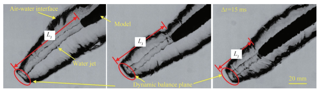 Figure 4 Selected close-up images of the cavity front corresponding to the data points shown in Figure 2 under CQs = 0.24, α = 37.3°, dN = 8 mm and Fr = 13.1. The time interval is 15 ms. The scale bar is applied to all three figures
The abovementioned hypothesis can be further supported by examining the experimental momentum ratio of the water jet and quiescent water. According to the experimental investigation and theoretical analysis of a static high-velocity gas jet impinging on quiescent water by Banks and Chandrasekhara (1963) and Banks and Bhavamai (1965), the cavity depth is dominated by the momentum ratio of the gas jet and quiescent water. In particular, the experimental data can be expressed by either (A): $\frac{M_{\mathrm{G}}}{\gamma n_0 d_{\mathrm{N}}^2}=\frac{\mathtt{π}}{\beta_*}\left(\frac{H+n_0}{d_{\mathrm{N}}}\right)^2 $ or (B): $\frac{M_{\mathrm{G}}}{\gamma n_0 d_{\mathrm{N}}^2}=\frac{\mathtt{π}}{\beta} $, which correspond to a relatively deep cavity or a very shallow cavity, respectively. These two formulas are based on the displaced liquid analysis, in which the force of the gas jet exerting on the liquid is equal to the weight of the displaced liquid. In addition, the depression is assumed to be sufficiently small that the change in the shape of the liquid surface does not appreciably alter the velocity and pressure distributions of the gas flow (Banks and Chandrasekhara, 1963). In this equation, $ M_{\mathrm{G}}=\rho_{\mathrm{G}} \frac{1}{4} \mathtt{π} d_{\mathrm{N}}^2 V_0^2$ is the momentum of the gas jet, ρG is the density of the gas, dN is the nozzle diameter, V0 is the jet velocity at the nozzle exit, γ = ρWg is the specific weight of the liquid, ρW is the density of the water, β = 2 and β* = 125 are the empirical constants, n0 is the cavity depth, and H is the distance from the nozzle exit to the water surface.
For the water entry cavity formed with a water jet cavitator, the moving liquid jet impacts the air-water interface and is submerged in water. Therefore, the water jet momentum can be written as $M_{\mathrm{W}}=\rho_{\mathrm{w}} \frac{1}{4} \mathtt{π} d_{\mathrm{N}}^2 V_0\left(V_0+U\right) $, and the displaced water (i.e., the weight of the cavity) can be written as γLCdN2 based on the study of Banks and Bhavamai (1965). Here, LC is the cavity length. The momentum ratio MW/γLCdN2 is also plotted in Figure 5. Although the momentum ratio of the water jet and quiescent water in our experiments do not match the experimental and theoretical results for a gas jet impinging on a water surface, the variation trend is similar. This disagreement can be explained by the moving water jet obliquely impinging on the quiescent water with a large cavity depth in our experiments versus the static gas jet vertically impinging the quiescent water with a small cavity depth in the work of Banks and Chandrasekhara (1963). The effects of the entry angle on the physical formation mechanism of the water entry cavity using a water jet cavitator will be discussed in detail in the following section.
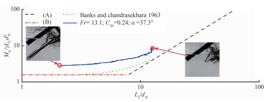 Figure 5 Momentum ratio of the water jet and quiescent water versus water jet length LJ under CQs = 0.24, α = 37.3°, dN = 8 mm and Fr = 13.1. (A) $\frac{M_{\mathrm{G}}}{\gamma n_0 d_{\mathrm{N}}^2}=\frac{\mathtt{π}}{\beta_*}\left(\frac{H+n_0}{d_{\mathrm{N}}}\right)^2 $; (B) $\frac{M_{\mathrm{G}}}{\gamma n_0 d_{\mathrm{N}}^2}=\frac{\mathtt{π}}{\beta}, M_{\mathrm{G}}=\rho_W \frac{1}{4} \mathtt{π} d_{\mathrm{N}}^2 V_0^2, \gamma=\rho_{\mathrm{W}} g, \beta_*=125 ; \beta=2 $
3.3 Effects of different parameters
The momentum ratio MW/γLCdN2 and corresponding typical experimental images are systematically summarized in Figures 6 and 7 under different Froude numbers (Fr), water jet rates (CQs), entry angles (α), and nozzle diameters (dN) to provide an example of the effects of different parameters on the physical formation mechanism of the water entry cavity using a water jet cavitator. Figure 6 corresponds to the results of dN = 6 mm, and Figure 7 corresponds to the results of dN = 8 mm. Figures 6‒7 correspond to the cases with entry angles of α = 37.3°, α = 47.2°, and α = 56.8°, respectively.
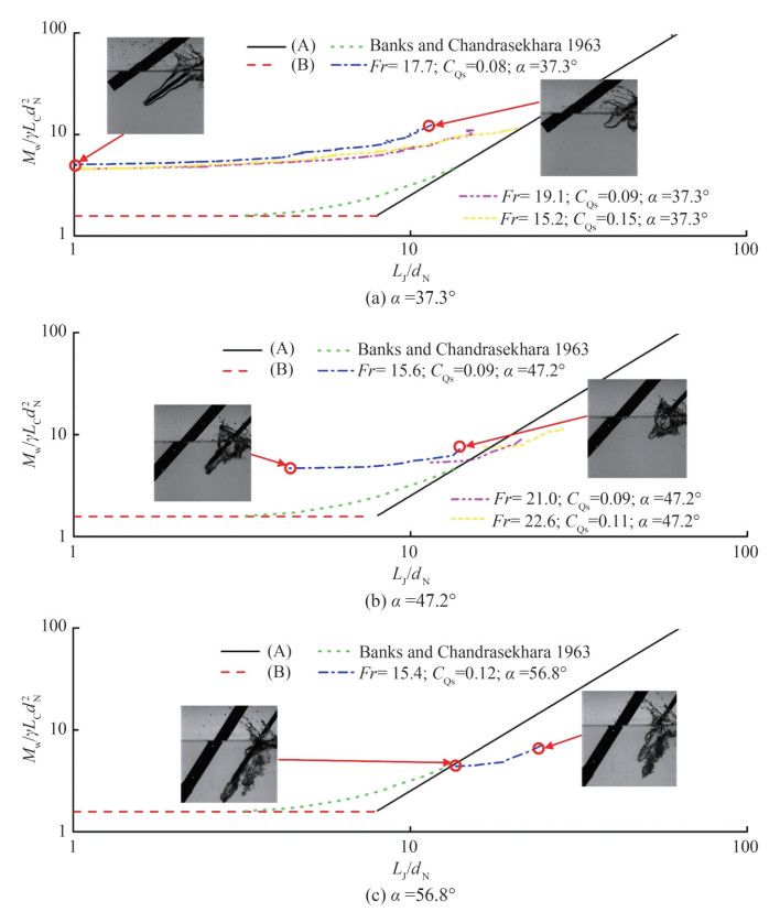 Figure 6 Momentum ratio MW/γLCdN2 versus water jet length LJ and corresponding typical experimental images of the nozzle diameter dN = 6 mm under different Froude numbers (Fr), water jet coefficient (CQs), and entry angles (α) for (a) α = 37.3°, (b) α = 47.2°, and (c) α = 56.8°
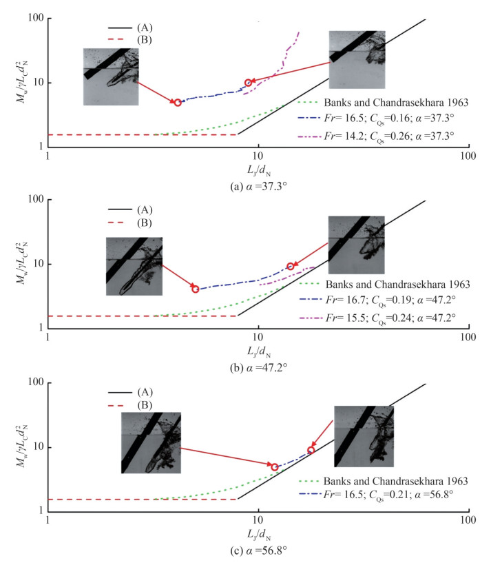 Figure 7 Momentum ratio MW/γLCdN2 versus water jet length LJ and corresponding typical experimental images of the nozzle diameter dN = 8 mm under different Froude numbers (Fr), water jet coefficient (CQs), and entry angles (α) for (a) α = 37.3°, (b) α = 47.2°, and (c) α = 56.8°
Although some experimental momentum ratios of the water jet and quiescent water do not match with previous experimental and theoretical results, they present a similar variation trend across all the test cases. This disagreement may also be attributed to the moving water jet obliquely impinging on the quiescent water with a large cavity depth in our experiments versus the static gas jet vertically impinging with a small cavity depth in the study by Banks and Chandrasekhara (1963). Moreover, the experimental data almost collapse into one curve for the same entry angle but different Froude numbers and water jet coefficients, especially in the case of dN = 6 mm as presented in Figures 6 and 7. This phenomenon occurs because MW/γLCdN2 includes the effect of the original variable U, V0, and dN and the limitation effect on the flow in the water entry cavity caused by the Froude number in our experimental range (Fr = 15.2–22.6) (Jiang et al., 2018a). Therefore, these results also support the abovementioned formation hypothesis of the water entry cavity using a water jet cavitator, i.e., the formation is mainly dominated by the location of the stagnation point moving downstream from the far field of the water jet to the exit of its nozzle with the increasing entry depth.
The entry angle significantly affects the flow characteristics of the water entry cavity. The momentum ratio versus water jet length curve varies under different entry angles, as shown in Figures 6 and 7. With the increase in entry angle (from 37.3° to 56.8°), the momentum ratio versus the water jet length curve moves from left to right. The larger the water entry angle, the longer the water jet length under the same momentum ratio. These characteristics can be attributed to the formation of the water entry cavity using a water jet cavitator. Some water droplet streams or jets impinge on the quiescent water surface before the formation of the stable stagnation plane, causing the quiescent water surface to move forward at a certain speed (He and Belmonte, 2010; Solorzano-Lopez et al., 2011; Vibaldi et al., 2013; Rabbi et al., 2021; Speirs et al., 2018). With the increase in entry angle, a large amount of water droplet streams or jets impinge on the quiescent water surface before the formation of the stable stagnation plane. The larger the water entry angle, the higher the front water moving velocity under the same momentum ratio corresponding to a longer water jet length after the stable stagnation plane is established.
Figures 6(c) and 7(c) contain less experimental data because the current experimental setup is prone to water turbulence at some large water entry angles. Hence, obtaining a clear cavity for image measurement is difficult. We conducted additional experiments on entry angles (α = 30°, 45°, 60°, 75°, 90°), water jet rates ($\dot{Q}_{\mathrm{A}}$ = 0.5–7 L/min), and another nozzle diameter (dN = 4 mm), as shown in Figure 8. However, the water entry cavity cannot be captured due to the limitation of the experimental device (the model only starts after the water jet is ejected from the model nozzle under the set flow rate) at some experimental conditions, such as vertical water entry and some large water entry angles, large water jet rate, and small nozzle diameter. Instead, a complex turbulence is formed. Thus, we only selected good experimental results for analysis. In the future, we will improve the experimental device to systematically perform experiments under different water entry angles, i.e., a water jet control system must be added to the existing experimental device to ensure that the water jet can be controlled when the model is close to the water surface.
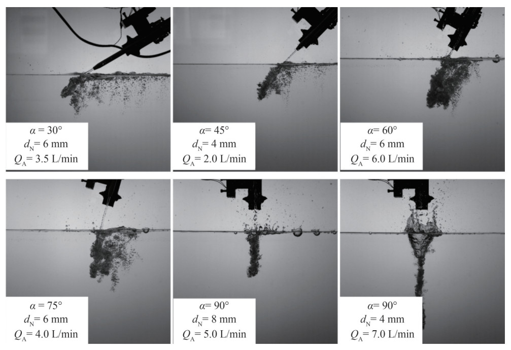 Figure 8 Selected experimental images to present different experimental conditions
4 Conclusions
On the basis of the experimental investigation of water entry with a water jet cavitator using the water entry water tank, some insights into the formation mechanism of the water entry cavity using a water jet cavitator under different flow conditions are obtained.
First, a gas bubble is created before the model impacts the water surface for the water jet cavitator. The width of the gas bubble increases as the model approaches the water surface prior to the impact. The length of the water jet gradually reduces to zero due to the quiescent water pressure increasing with the penetration depth.
Second, the formation of the water entry cavity using a water jet cavitator is directly correlated with the location of the stagnation point moving downstream from the far field of the water jet to the exit of its nozzle with the increasing entry depth. The momentum ratio of the water jet and quiescent water presents a similar variation trend to the experimental and theoretical results of a gas jet impinging on the water surface.
Third, all the momentum ratio experimental data almost collapse into one curve for the same entry angle but different Froude numbers and water jet rates. These findings also support the formation mechanism hypothesis of the water entry cavity using a water jet cavitator. The larger the water entry angle corresponding to many water droplet streams or jets impinging on the quiescent water surface before the formation of the stable stagnation plane, the higher the front water moving speed under the same momentum ratio corresponding to the long water jet length after the stable stagnation plane is established.
Competing interest The authors have no competing interests to declare that are relevant to the content of this article. -
Figure 1 (a) Schematic of the water entry tank facility and model of the water entry cavitation with a water jet cavitator; (b) Image and the dimension of the model with a water jet cavitator
Figure 2 (Multimedia view) (a)Typical image showing the water entry cavitation with a water jet cavitator. (b) Selected formation images of the water entry cavitation with a water jet cavitator (i.e., CQs = 0.24, α = 37.3o and dN = 8 mm) under Fr = 13.1. The time interval is 10 ms. The multimedia view video is recorded with 4k fps and playback of 30 fps
Figure 3 Schematic of the flow field in the water entry cavity formed using a water jet cavitator
Figure 4 Selected close-up images of the cavity front corresponding to the data points shown in Figure 2 under CQs = 0.24, α = 37.3°, dN = 8 mm and Fr = 13.1. The time interval is 15 ms. The scale bar is applied to all three figures
Figure 5 Momentum ratio of the water jet and quiescent water versus water jet length LJ under CQs = 0.24, α = 37.3°, dN = 8 mm and Fr = 13.1. (A) $\frac{M_{\mathrm{G}}}{\gamma n_0 d_{\mathrm{N}}^2}=\frac{\mathtt{π}}{\beta_*}\left(\frac{H+n_0}{d_{\mathrm{N}}}\right)^2 $; (B) $\frac{M_{\mathrm{G}}}{\gamma n_0 d_{\mathrm{N}}^2}=\frac{\mathtt{π}}{\beta}, M_{\mathrm{G}}=\rho_W \frac{1}{4} \mathtt{π} d_{\mathrm{N}}^2 V_0^2, \gamma=\rho_{\mathrm{W}} g, \beta_*=125 ; \beta=2 $
Figure 6 Momentum ratio MW/γLCdN2 versus water jet length LJ and corresponding typical experimental images of the nozzle diameter dN = 6 mm under different Froude numbers (Fr), water jet coefficient (CQs), and entry angles (α) for (a) α = 37.3°, (b) α = 47.2°, and (c) α = 56.8°
Figure 7 Momentum ratio MW/γLCdN2 versus water jet length LJ and corresponding typical experimental images of the nozzle diameter dN = 8 mm under different Froude numbers (Fr), water jet coefficient (CQs), and entry angles (α) for (a) α = 37.3°, (b) α = 47.2°, and (c) α = 56.8°
Figure 8 Selected experimental images to present different experimental conditions
-
Banks RB, Chandrasekhara DV (1963) Experimental investigation of the penetration of a high-velocity gas jet through a liquid surface. Journal of Fluid Mechanics 15(1): 13–34. https://doi.org/10.1017/S0022112063000021 Banks R B, Bhavamai A (1965) Experimental study of the impingement of a liquid jet on the surface of a heavier liquid. Journal of Fluid Mechanics 23(2): 229–240. https://doi.org/10.1017/S0022112065001325 Bodily KG, Carlson SJ, Truscott TT (2014) The water entry of slender axisymmetric bodies. Physics of Fluids 26: 072108. https://doi.org/10.1063/1.4890832 Bostwick JB, Steen PH (2010) Stability of constrained cylindrical interfaces and the torus lift of Plateau-Rayleigh. Journal of Fluid Mechanics 647: 201–219. https://doi.org/10.1017/S0022112009993831 Eggers J (1995) Theory of drop formation. Physics of Fluids 7: 941–953. https://doi.org/10.1063/1.868570 Grubelnik V, Marhl M (2005) Drop formation in a falling stream of liquid. American Journal of Physics 73(5): 415–419. https://doi.org/10.1119/1.1866100 He A, Belmonte A (2010) Deformation of a liquid surface due to an impinging gas jet: A conformal mapping approach. Physics of Fluids 22(4): 042103. https://doi.org/10.1063/L3327209 Hwang HY, Irons GA (2012) A water model study of impinging gas jet on liquid surfaces. Metallurgical and Materials Transactions B 43(2): 302–315. https://doi.org/10.1007/s11663-011-9613-3 Jiang Y, Bai T, Gao Y (2017) Formation and steady flow characteristics of ventilated supercavity with gas jet cavitator. Ocean Engineering 142: 87–93. https://doi.org/10.1016/j.oceaneng.2017.06.054 Jiang Y, Shao S, Hong J (2018a) Experimental investigation of ventilated supercavitation with gas jet cavitator. Physics of Fluids 30(1): 012103. https://doi.org/10.1063/L5005549 Jiang Y, Bai T, Gao Y, Guan L (2018b) Water entry of a constraint posture body under different entry angles and ventilation rates. Ocean Engineering 153: 53. https://doi.org/10.1016/j.oceaneng.2018.01.091 Jiang Y, Zou Z, Yang L, Shen L, Liu Y, Zhang M (2023a) Reduction of water entry impact force by a gas jet. Physical Review Fluids 8(6): 064005. https://doi.org/10.1103/PhysRevFluids.8.064005 Jiang Y, Hong J, Pham V, Ahn B (2023b) Experimental study on supercavitating flow by injection of 773 K ventilated gas. European Journal of Mechanics/B Fluids 99: 136–147. https://doi.org/10.1016/j.euromechflu.2023.01.006 Kimerer (2012) Removable protective nose cover. Patent No. US 8, 093, 487B2 Lee M, Longoria RG, Wilson DE (1997) Cavity dynamics in high-speed water entry. Physics of Fluids 9: 540–550. https://doi.org/10.1063/1.869472 Li S, Zhao ZS, Zhang AM, Han R (2024) Cavitation bubble dynamics inside a droplet suspended in a different host fluid. Journal of Fluid Mechanics 979: A47 https://doi.org/10.1017/jfm.2023.1076 Liu WT, Zhang AM, Miao XH, Ming MF, Liu YL (2023) Investigation of hydrodynamics of water impact and tail slamming of high-speed water entry with a novel immersed boundary method. Journal of Fluid Mechanics 958: A42. https://doi.org/10.1017/jfm.2023.120 Marston JO, Truscott TT, Speirs NB, Mansoor MM, Thoroddsen ST (2016) Crown sealing and buckling instability during water entry of spheres. Journal of Fluid Mechanics 794: 506–529. https://doi.org/10.1017/jfm.2016.165 May A (1975) Water entry and the cavity-running behavior of missiles. Technical Report 20910. Springfield: National Technical Information Service Mishra A, Yadav H, Djenidi L, Agrawal A (2020) Experimental study of flow characteristics of an oblique impinging jet. Experiments in Fluids 61(3): 1–16. https://doi.org/10.1007/s00348-020-2923-y Muñoz-Esparza D, Buchlin JM, Myrillas K, Berger R (2012) Numerical investigation of impinging gas jets onto deformable liquid layers. Applied Mathematical Modelling 36(6): 2687–2700. https://doi.org/10.1016/j.apm.2011.09.052 Rabbi R, Speirs NB, Kiyama A, Belden J, Truscott TT (2021) Impact force reduction by consecutive water entry of spheres. Journal of Fluid Mechanics 915:A55. https://doi.org/10.1017/jfm.2020.1165 Rayleigh L (1878) On the instability of jets. Proceedings of the London Mathematical Society 1(1): 4–13. https://doi.org/10.1112/plms/s1-10.1.4 Rayleigh L (1879) On the capillary phenomena of jets. Proceedings of the Royal Society of London 29: 71–79. https://www.jstor.org/stable/113738 Roy AK, Kumar K (2018) Experimental studies on hydrodynamic characteristics using an oblique plunging liquid jet. Physics of Fluids 30(12): 122107. https://doi.org/10.1063/L5058123 Seddon CM, Moatamedi M (2006) Review of water entry with applications to aerospace structures. International Journal of Impact Engineering 32(7): 1045–1067. https://doi.org/10.1016/j.ijimpeng.2004.09.002 Subbotin A V, Skvortsov IY, Kuzin M S, Gerasimenko PS, Kulichikhin VG, Malkin YA (2021) The shape of a falling jet formed by concentrated polymer solutions. Physics of Fluids 33(8): 083108. https://doi.org/10.1063/5.0060960 Solorzano-Lopez J, Zenit R, Ramirez-Argaez MA (2011) Mathematical and physical simulation of the interaction between a gas jet and a liquid free surface. Applied Mathematical Modelling 35(10): 4991–5005. https://doi.org/10.1016/j.apm.2011.04.012 Speirs NB., Pan Z, Belden J, Truscott TT (2018) The water entry of multi-droplet streams and jets. Journal of Fluid Mechanics 844: 1084–1111. https://doi.org/10.1017/jfm.2018.204 Truscott TT, Techet AH (2009) Water entry of spinning spheres. Journal of Fluid Mechanics 625: 135–165. https://doi.org/10.1017/S0022112008005533 Truscott TT, Epps BP, Techet AH (2012) Unsteady forces on spheres during free-surface water entry. Journal of Fluid Mechanics 704: 173–210. https://doi.org/10.1017/jfm.2012.232 Truscott TT, Epps BP, Belden J (2014) Water entry of projectiles. Annual Review of Fluid Mechanics 46: 355–378. https://doi.org/10.1146/annurev-fluid-011212-140753 Vivaldi D, Gruy F, Simon N, Perrais C (2013) Modelling of a CO2-gas jet into liquid-sodium following a heat exchanger leakage scenario in sodium fast reactors. Chemical Engineering Research and Design 91(4): 640–648. https://doi.org/10.1016/jxherd.2013.02.011 Worthington AM, Cole RS (1897) Impact with a liquid surface, studied by the aid of instantaneous photography. Philosophical Transactions of the Royal Society A 189: 137–148. https://doi.org/10.1098/rsta.1897.0005 Xiong CW, Wang SZ, Dong QQ, Wang SP, Zhang AM (2024) On the interfacial instabilities of a ventilation cavity induced by gaseous injection into liquid rossflow. Journal of Fluid Mechanics 980: A44. https://doi.org/10.1017/jfm.2024.23 Zhang AM, Li SM, Cui P, Li S, Liu YL (2023) A unified theory for bubble dynamics. Physics of Fluids 35: 033323. https://doi.org/10.1063/5.0145415 Zhang Q, Ming F, Liu X, Liu W, Zhang A (2023) Experimental investigation of the dynamic evolution of cavity during the free water-exit of a high-pressure venting vehicle. Physics of Fluids 35: 122118. https://doi.org/10.1063/5.0176671 Zhu Y, Oğuz HN, Prosperetti A (2000) On the mechanism of air entrainment by liquid jets at a free surface. Journal of Fluid Mechanics 404: 151–177. https://doi.org/10.1017/S0022112099007090
