
A Succinct Review on the Numerical and Experimental Performance Evaluation Techniques for Composite Marine Propellers
https://doi.org/10.1007/s11804-024-00442-1
-
Abstract
Understanding the behaviour of composite marine propellers during operating conditions is a need of the present era since they emerge as a potential replacement for conventional propeller materials such as metals or alloys. They offer several benefits, such as high specific strength, low corrosion, delayed cavitation, improved dynamic stability, reduced noise levels, and overall energy efficiency. In addition, composite materials undergo passive deformation, termed as "bend-twist effect", under hydrodynamic loads due to their inherent flexibility and anisotropy. Although performance analysis methods were developed in the past for marine propellers, there is a significant lack of literature on composite propellers. This article discusses the recent advancements in experimental and numerical modelling, state-of-the-art computational technologies, and mutated mathematical models that aid in designing, analysing, and optimising composite marine propellers. In the initial sections, performance evaluation methods and challenges with the existing propeller materials are discussed. Thereafter, the benefits of composite propellers are critically reviewed. Numerical and experimental FSI coupling methods, cavitation performance, the effect of stacking sequence, and acoustic measurements are some critical areas discussed in detail. A two-way FSI-coupled simulation was conducted in a non-cavitating regime for four advanced ratios and compared with the literature results. Finally, the scope for future improvements and conclusions are mentioned.-
Keywords:
- Cavitation studies ·
- Composite propellers ·
- Hydro-elasticity ·
- Numerical model ·
- Acoustics vibration
Article Highlights● A thorough review of current investigation methods for composite marine propeller.● Strong focus and review on the experimental and numerical models used within the literature and how they could be used for performance analyses and potentially improvements.● Highlighting current technology weakness and how they could be improved.● Discussion on the effect of stacking sequence, acoustics and cavitation on performance of composite propeller. -
1 Introduction
The emphasis and need for sustainable growth, greener fuel, carbon neutral environment and renewable energy has increased very significantly in the maritime sector due to the acute rise in fossil fuel prices and looming restrictions on the emission of GHGs and noise pollution from government and non-government agencies with an aim to protect the environment. The automobile and freight sectors have begun to revamp themselves to accommodate more efficient and eco-friendlier EVs with a lower power requirement (Sivakumar et al., 2018). However, the shipping industry, a significant stakeholder in the transportation division, which carries over 90 percent of the world's merchandise trade via international waters and seaports, still largely depends on fossil fuels for its smooth operation. According to the IMO, the shipping industry contributes about 3 percent of CO2, 18 to 30 percent of NOx, 10 percent of SOx, and other toxic pollutants to GHG emissions (Reuters, 2019). Furthermore, URN generated due to various sources of shipping activities has created a greater nuisance to marine habitats. Due to the actions in the past and some in the present global climate change and acidification have become a major threat to our planet's sustainability.
Hence, designers and engineers should look for alternative energy and material sources with lower emission rates and improve performance during operations. Several reforms have been implemented, and many more are under way (particularly in ships) to meet international standards and regulations, including the EEDI and EEXI, as suggested by IMO. The apex bodies have recommended energy-efficient technologies to enhance efficiency and reduce emissions, categorised into four groups: machinery, energy consumption, optimising operation, and hull improvement groups. Figure 1 presents some of the IMO-suggested areas and possible percentage reductions by incorporating green technologies. They propose optimising parameters such as speed, voyage management, hull and propeller modifications, alternate fuels, and ballast water management. Improvements in propellers and their associated systems are one of the significant zones of research, and the same is focused on in this paper.
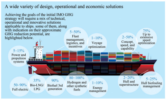 Figure 1 IMO suggestion for decarbonisation (International Maritime Organisation, 2019)
Since the inception of screw propellers and their installation in the SS Archimedes in 1939, sound and significant modifications have been made in design methodology, geometric parameters, development techniques, manufacturing methods, and material selections to improve the hydrodynamic performance at design operating conditions. However, only homogeneous metals and alloys were primarily chosen as propeller materials. These materials have several challenges while working in maritime environments, and the demand for alternative materials was realised. Since the late 20th century, composite materials have emerged as an alternative to traditional ones with better mechanical properties and performance characteristics. They were widely adopted in various parts of the hull, such as the superstructure, hatch, mast, propellers, and bulkheads. Nakashima Propeller Company (2015) carried out one recent study regarding the installation of a full-scale CFRP propeller on a 499 GT chemical tanker named "Taiko Maru". The reports revealed that the propeller weight has come down to 59%, and the power consumption has reduced to 9% during the sea trials. The vibration has reduced tremendously despite increasing the diameter of CFRP.
This paper will primarily discuss the performance evaluation of adaptive marine propellers, especially those based on composite material to replace conventional materials, starting from the need, design requirements, and estimation of hydroelastic characteristics using numerical and experimental methods. Details about the coupling methods (both inviscid and viscous), cavitation responses, and noise characteristics of the composite propellers are also discussed. Finally, a numerical prediction of hydroelastic responses for P1790 is also presented. Composite material testing, microstructural analysis, design methodology, manufacturing technique, product development, and vibration of the composite propellers are not in the scope of the paper. Figure 2 represents the overall sections and its significance of the paper on CMPs.
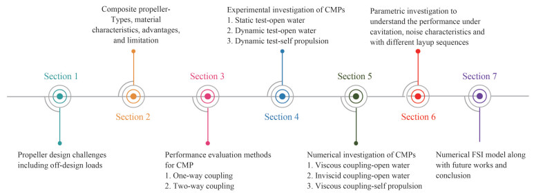 Figure 2 Overview of the sections and their significance
1.1 Propeller design challenges
The propeller is an integral part of the hull that aims to produce the desired thrust to overcome the drag force by converting the rotational energy into a linear propulsive force perpendicular to its plane of rotation. It has several blades and a boss cap connected via a shaft to the prime mover, generally located aft of the ship. It is a complex 3D shape geometry set at a pitch and rotates at a constant revolution to produce a helical spiral and exert thrust on the working fluid. The propellers are subjected to different loads such as hydrodynamic, cavitation, centrifugal, and Coriolis forces while operating underwater. Hence, it is essential to design the propeller by considering hull parameters such as wake fraction, thrust deduction fraction, hull resistance, and other design loads to achieve maximum thrust and efficiency at operating conditions. Propellers are often designed using the standard series diagram or the wake information (Ghose and Gokarn, 2015), and their performances are estimated using experiments. The open water experiment is a conventional test performed at a towing tank facility to understand the performance of the designed propeller under uniform inflow conditions. Their performances are estimated by evaluating thrust, torque, and open-water efficiency.
Additionally, self-propulsion tests are performed to evaluate the performance of the propellers in the behind-hull Figure 1 IMO suggestion for decarbonisation (International Maritime Organisation, 2019) condition. It is a replica of the service condition, where the propeller is fitted to the aft part of the ship. Both the design and analysis processes assume that the propeller is rigid with fixed geometry. While operating, numerous loads act on the propeller, including hydrodynamic, centrifugal, cavitation, biofouling, and the Coriolis effect. Hence, the propeller material plays a vital role even at the early design stage. Improper design and selection of the material of the propeller will reduce its performance and may lead to failure or breakage. Conventional propeller materials are nickel, aluminium bronze, manganese bronze, aluminium, and steel, with either a fixed pitch or controllable pitch employed in almost all ocean-going ships. They are rigid, isotropic, and strong, with higher stiffness to withstand all the loads during design and off-design states. However, some of their mechanical properties are undesirable, such as their low strength-to-weight ratio, cavitation, corrosion, and poor vibration properties, which reduce efficiency and increase fuel consumption with ageing. Furthermore, noise from the conventional propeller also damages the marine ecosystem, and for naval ships, it is even more challenging as they become more vulnerable to rivals. Figure 3 represents the challenges associated with conventional materials as a diagrammatic representation.
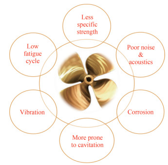 Figure 3 Challenges associated with conventional propeller materials
1.2 Propeller under off-design loads
The propeller is commonly designed for calm water conditions, but during the operation, it works in ocean waves where a heterogeneous inflow is experienced. This will require more power to achieve the same speed, increasing fuel consumption. In the literature, very limited studies are available on the design of propellers under off-design conditions. However, some literature is discussed below where mission-based designs were carried out.
Grigoropoulos et al. (2017) proposed a study to optimise the propeller operating under unsteady wake conditions. The numerical model considered four cases in one wake cycle of a regular wave. Initially, the individuals generated within the design area were evaluated with limited constraints, which were later increased to achieve an optimum. In the second stage, the cavitation condition was evaluated, and many showed small clouds near the leading and trailing edges. Ortolani et al. (2018) estimated the propeller loads in off-design conditions using experimental and numerical methods. In-plane loads were measured using a novel transducer for manoeuvring studies. Numerical simulations were also carried out using the unsteady RANSE and BEM methods. During the external phase of operation under pure oblique flow, the load increment was linear to the rudder angle, and the side force developed up to 30% of the thrust generated during the approach phase. In the internal phase, the wake affected the propeller loading, and unsteady loading was observed with similar thrust and torque values compared to the external phase.
Ortolani and Dubbioso(2019a, 2019b) investigated the propeller blade loads under straight line and steady turn conditions. In the former test, free-running manoeuvring experiments were conducted, and blade loads were estimated with a six-component load cell. Due to the complex inflow, the blade experienced more significant loading, which in turn affected the performance. In the later study, manoeuvring investigations were carried out for twin screw vessels at different operating speeds. It was reported that the windward and leeward sides behaved differently due to the wake variations. These caused several variations in the propeller load and significantly affected its performance. Dubbioso et al. (2022) studied a candidate hull's acoustic properties under the wake field's effect during manoeuvring motion. The primary focus was developing noise control strategies, emphasising passive and active control. The passive control was primarily concerned with modifying the stern appendages and changing the rotational direction of the propeller. In contrast, the active control was concerned with limiting the power and load absorption. The noise was measured using RANSE-BEM, and Farassat Formulation 1A-Solutions used for acoustic predictions was used for acoustic projections. Overall, the SPL was plotted for different rudder angles on the leeward and windward sides. Detailed discussions were presented on the increase in propeller loading and, thereby effect on acoustic prediction in both cavitation-free and cavitation conditions. Hence, from the above literature studies, it is understood that there is a need to consider the off-design parameters to incorporate in the initial design.
1.3 Composite propellers
To eliminate the problems due to conventional materials and improve the efficiency at operating conditions, ship owners, naval architects, marine engineers, and other researchers are developing various solutions by optimising the blade geometry and intelligent materials. The literature shows that blade geometry has been optimised to the maximum extent and that the scope for further optimisation is limited. Hence, there is a search for the replacement of propeller materials that can offer a better solution. Composite material has been identified as a better alternative to conventional material. It is developed by combining two materials, reinforcement and matrix, which offer better physical properties than the individual ones. They possess superior properties to their metallic counterparts, including high specific strength, resilience, improved acoustic and vibration characteristics, reduced cavitation, corrosion resistance, resistance to chemicals and reagents, and galvanic cell formation (Young et al., 2017). The fuel consumption is reduced by 15 percent, and the vehicle provides improved acceleration (Marsh, 2004). However, these materials are not widely used because of their anisotropy and low stiffness. They deflect or deform during operation, and since they are brittle, they fail without yielding, which is highly detrimental to ship owners.
1.4 Composite material types
Composite materials are developed by combining the reinforcement/fibre material, matrix/resin, and softcore materials in the case of sandwich laminates. There are man-made as well as natural composite materials. Natural composites are mainly from plants and animals, which are low-cost, eco-friendly, and renewable substances. In the past, mud bricks were used for building construction and were formed by combining mud bricks and straws. This is a typical example of a natural composite. However, synthetic or man-made fibres are more popular among researchers and scientists due to their improved properties and availability than natural composites. Figure 4 represents the different types of composites available on the market.
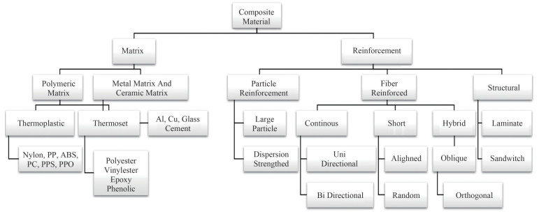 Figure 4 Types of synthetic or man-made composite material
Even though the marine industry has started to adopt composite materials more recently, only a few reinforcement and matrix materials are suitable for sustaining this environment. In the case of propellers, the most commonly used materials are glass and carbon fibre. Glass fibres are readily available and cost-effective compared to carbon fibre. The former was initially adopted as a replacement but underperformed as expected due to its high flexibility by undergoing larger deformations. The latter proved its character with high stiffness, rigidity, and resistance to corrosion, cavitation, and fatigue cycles. Thus, the carbon fibre reinforcement material replaces conventional materials with similar structural behaviour during operating conditions.
The most commonly used matrix materials are epoxy, polyester, and vinyl esters. Despite the higher cost, epoxy is preferred over others in most cases due to its strength properties, such as shock force, impact force, thermal resistance, corrosion resistance, and resistance to chemical actions.
Nonetheless, controlled hydroelastic tailoring methods could favourably shape the flexible behaviour of composite propellers for better performance. They reduce active systems' complexities, operational skills, maintenance, and high investment requirements. Since the propeller pitch varies at each radial section due to the highly complicated three-dimensional shape, active systems, and non-uniform inflow, they underperform the actual condition. Hence, it is wiser to consider the composite propeller as a replacement.
Cavitation is a crucial phenomenon in the marine propeller, which leads to material erosion due to fatigue loads generated by bubbles. Conventional materials suffer severely, with a significant decay in performance and efficiency. Sometimes, the breakage of the blades is due to cavitation. Numerical and experimental investigation reveals that flexible propellers have outperformed rigid propellers by delaying cavitation inception speed. Due to the self-adaptive nature of composite during loading, the load over a given blade area tends to stay within the limits at which implosion of cavities against the blade is induced.
In addition, the composite marine propeller has betterdamping characteristics than metals or alloys. Properties such as non-magnetic and reduced acoustic signature emission allow using these materials as an alternative to traditional ones.
The composite propeller's performance also depends on structural rigidity and integrity. The intrinsic behaviour due to anisotropy and low stiffness allows it to deform during the load condition. Although deformation is a positive aspect, extensive deformation leads to poor performance and reduced efficiency. Hence, proper stacking sequence (the order in which fibres are laid one after another) required controlled deformation that could be identified using material coupon tests or numerical simulations. Per-deformation has sometimes proven to be an effective design that yields within limits for better performance.
With numerous superior characteristics, composite materials emerged as one of the strongest alternative materials of choice, replacing conventional metals or alloys. Although limited explorations have been conducted on understanding and computing composite marine propellers' behaviour, performance, and efficiency, several breakthroughs and milestones have been achieved, especially in numerical methods.
The mimic approach or model test methods were arduous, involving several levels of expertise and infrastructure. With the development of modern computers and numerical methods, researchers focused more on numerical modelling for quicker and more reliable results that were widely accepted. The process was also extended for the parametric investigation to save time and money. Hence, numerical models emerged as an optimum solution for composite marine propellers' design, development, and performance analysis.
1.5 Performance evaluation
The performance evaluation of any CMPs shall be carried out in two forms after satisfying successful design criteria. Figure 4 illustrates the potential methods adopted for estimating the characteristics of CMPs. In experimental methods, CMPs can be subjected to hydrodynamic and hydro-elastic investigations in towing tanks, water channels, or cavitation tunnel facilities by employing suitable instrumentation such as thrust and torque transducers, DIC, and high-speed cameras. Under several circumstances, the possibility of conducting experiments becomes nearly impossible. In those cases, the solutions are obtained using numerical solvers incorporating the flexible nature of composites using viscid or inviscid solvers in both uncoupled and coupled methods. The exact behaviour of CMPs is mimicked numerically using coupled (two-way) methods, as indicated in green colour in Figure 4. Although there are two methods, viscous is reliable and provides better accuracy. Many researchers have also used uncoupled viscid and inviscid solvers for performance analysis of CMPs for initial estimation, as indicated in yellow colour in Figure 4. Due to the limitations of the inviscid solver, the solutions are predominantly used only during the initial design stages. The rigid analysis in red colour in Figure 5 does not provide precise performance estimates for CMPs.
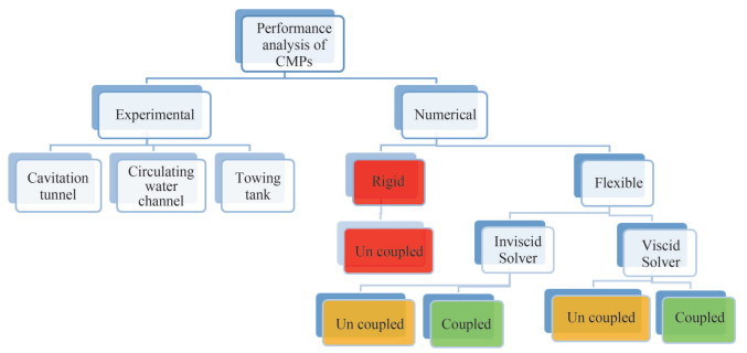 Figure 5 Methods of performance analysis CMPs
1.6 Hydrodynamic performance parameter
The critical parameters of the hydrodynamic performance of any propeller are thrust, torque, and efficiency. The below equations represent them in non-dimensional form as thrust coefficient, torque coefficient, and efficiency for estimating the open water characteristics (Kumar et al., 2019).
$$ K_T=\frac{T}{\rho n^2 d^4} $$ (1) $$ K_Q=\frac{Q}{\rho n^2 d^5} $$ (2) $$ \eta_0=\frac{K_T J}{K_Q 2 \pi} $$ (3) The propeller is considered rigid during the evaluation, and the material's structural properties are ignored. However, for hydroelastic-based estimation, the assumption is no longer valid, and it is mandatory to incorporate the structural properties.
1.7 Summary of literature
A systematic survey for the collection of literature was carried out, and a summary of the same is presented in Figure 5. Although there is no extensive literature on composite marine propellers, continuous efforts were made to collect as much as possible. Figure 6(a) illustrates a collection of articles from different literature sources. More than three-fourths were refereed journal papers, followed by conference publications. A few dissertations, books, manuals, magazines, and newspaper articles were also considered for review. Figure 6(b) demonstrates the year-wise data published on adaptive marine propellers. It emphasises that substantial research was carried out only in the last decade. Figures 6(c)‒6(d) show how much experimental and numerical work has been conducted on composite propellers respectively. Most of the experimental work was carried out in the cavitation tunnel and numerically used the viscous and inviscid coupled method. The kinds of literature discussed in this article are classified into two categories:
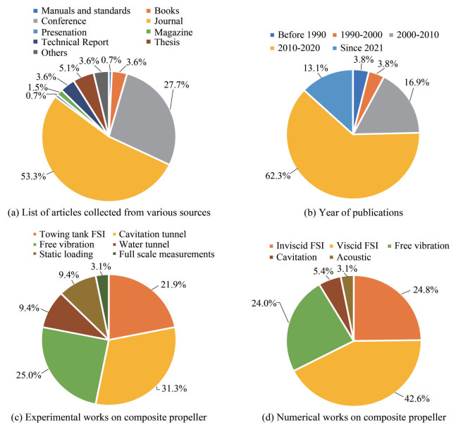 Figure 6 Methods of performance analysis CMPs
1) Experimental investigation–Dynamic and static.
2) Numerical investigation–Inviscid and viscid.
2 Hydro-elastic method-FSI coupling method overview
In the case of metal, propellers are assumed to be fixed and rigid during the entire analysis process, neglecting the deformation characteristics as they are highly insignificant and do not alter the propeller's performance. The same assumption becomes invalid for composite marine propellers due to their anisotropy and flexibility. The deformation is comparatively significant compared with conventional materials and alters the fluid inflow to the propeller. In addition to hydrodynamic analysis, estimating structural behaviour for composite propellers becomes highly important. Thus, the hydroelastic or fluid-structure interaction method is adopted for estimating the performance characteristics of the composite marine propeller. There are two methods of performing FSI analysis: weak or one-way coupling and strong or two-way coupling.
In the one-way approach, the fluid analysis's mass, momentum, and energy quantities are transferred to the structural model without feedback. The weak coupling model requires only one solution to each problem during a time step. Figure 7 illustrates the flowchart for the one-way coupling method. Unlike the one-way coupling method, there is a feedback mechanism from the structural solver within the same time step, and deformation alters the geometry shape for the two-way coupling method. To achieve convergence consistently, small-time steps are preferred. Figure 8 explains the two-way coupling method. The Fully Coupled approach forms a single large system of equations that solve for all unknowns (the variables) and includes all of the couplings between (the multiphysics effects) simultaneously within a single iteration. Figure 9 illustrates the coupling mechanism for various applications and found that two-way coupling is best suited for any blade deformation studies.
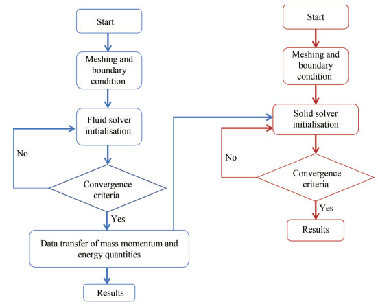 Figure 7 One-way coupling method
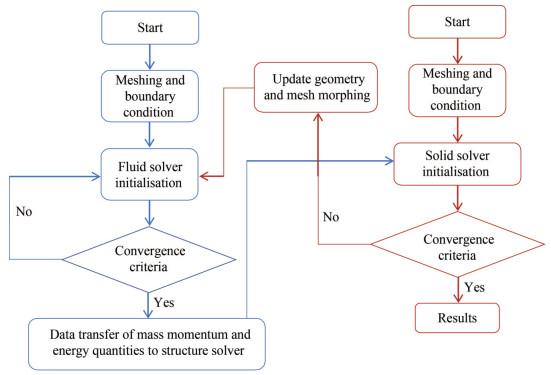 Figure 8 Two-way coupling method
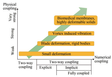 Figure 9 FSI coupling method
3 Experimental investigation
The experimental study provides a thorough understanding of the dynamics of the accurate flow past underwater vehicles. However, due to the higher cost and complexities, completing hydrodynamic tests for each example of realistic flows is practically unfeasible. Very few experimental studies in the open literature investigate the hydroelastic characteristics of marine propellers, which are reviewed in this section. They are classified into static and dynamic load analysis.
3.1 Static analysis
The researchers had striven and progressed continuously to simplify the problem and look for quicker results, which will be useful at the initial design stage. The initial set of results was estimated by the static loading condition, where the pressure values at various radial sections are calculated using the numerical models. These loads are placed as concentrated loads, and deflection shall be measured at static conditions. In other words, it can be described as a oneway experimental FSI analysis. Although several deflection experiments, including simplified beam analysis, are available in the open domain, this section restricts discussion regarding the composite propeller in recent years.
Maljaars et al. (2017) performed static deflection measurements by fixing the blades on a turning lathe. PVC balls were used to apply the forces, and the blade's structural responses were measured using the DIC technique. Kumar et al., (2019) investigated a carbon fibre propeller with podded propulsion to identify the tip deflection under operating conditions. Numerical simulations were carried out to identify the blade pressure values at each r/R (radial section) section and apply a load by hanging weights. The static displacement was observed using height gauges, and the same was compared with numerical results. Figure 10 illustrates the segmented loading of the CFRP propeller.
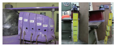 Figure 10 Segmented loading for static deflection analysis (Kumar et al., 2019)
Rokvam et al. (2021) carried out an experimental investigation on a 600 mm composite propeller blade to predict the structural deformation response due to point loads. DIC and strain gauges were used to identify the patterns of deformation in the composite propeller, and numerical model investigations were conducted using FEM. It was observed that DIC and FEM results matched very closely. establishing that DIC could be used for measuring deformation for existing flexible propellers.
3.2 Dynamic analysis-open water
Dynamic analysis was carried out in addition to static analysis to understand the complete performance and behaviour of CMPs. According to Mouritz et al. (2001), one of the earliest implementations and tests of CMPs with a diameter of around two metres on a Soviet fishing vessel occurred in the 1960s, with diameters increasing to six metres in the 1970s. Colclough and Russell (1972) worked on developing a full-scale composite propeller for a hovercraft to minimise the threat of noise, corrosion, and erosion from a propeller made of conventional materials using a carbon fibre-reinforced plastic spar. Numerous coupon tests were conducted to establish CFRP's mechanical properties, such as tensile force, flexural, torsional, and interlaminar shear strength. In addition to the coupon test, modelscale propellers were developed and tested for strength, fatigue, and deflection.
Chen et al. (2006) conducted an experimental and numerical analysis with a flexible propeller made of CFRP material at the Naval Surface Warfare Center's Carderock Division. Three different propellers were experimentally tested for hydrodynamic and elastic characteristics with and without circumferentially varying wake conditions, and at four different locations, the pitch angle was measured. It was discovered that approximately 5% of the increase in hydrodynamic efficiency and improvement in cavitation properties reached 50%. A finished composite propeller blade is shown in Figure 11.
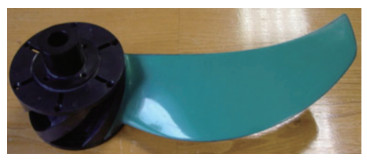 Figure 11 A finished composite propeller blade (Chen et al., 2006)
Lin et al. (2009) performed one of the earliest full-fledged experiments on the composite propeller in a cavitation tunnel. Two layup sequences considered for the DTNSRDC 4498 propeller hydrodynamic and hydroelastic analysis, where one is quasi-isotropic, and another is an optimum sequence developed using a genetic algorithm and a predeformed design with the same sequence, were considered for experimentation. Propellers were rotated at three RPSs: 7, 13, and 20. Figure 12 illustrates the final developed form of the CFRP composite propeller.
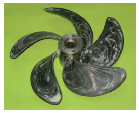 Figure 12 DTNSRDC 4498 composite propeller (Lin et al., 2009)
The experiments were carried out to identify thrust and torque coefficients and leading edge and trailing edge deflection for all three models. The results showed that the optimised propeller exhibited less torque with greater efficiency and produced less deformation than the original and pre-deformed propeller. Hara et al.(2011) conducted a cavitation test for three different propellers made of PVC material to estimate the hydro-elastic performance. Furthermore, CFRP propellers were developed and tested with two different stacking sequences. The study aimed to develop an optimisation method for CFRP propellers through FSI analysis using the LST method at the initial stage and CFD at the later stage. The developed methods followed the same trend as the experiment results, including displacement. Paik et al. (2013) performed an experimental investigation on a fixed-pitch model-scale propeller made of carbon and glass fibre to establish performance characteristics. The open-water experimental results were compared with those of the metal propeller at different advanced velocities. There was no significant difference in performance between composite propellers with J = 0.5 − 1 and became more deformation where J > 1. Carbon composite propellers outperformed glass composite propellers. However, the glass fibre propeller deflects largely more than the CFRP composite propeller, and it was found that the thrust and advance ratios greatly influence the flexibility. Wake profiles at slipstreams were compared, and it was found that the glass fibre propeller produced a lower velocity distribution. It was reported that the acoustic performance of glass composite propellers was appreciable compared to carbon composite. Huang et al. (2016) conducted experiments on the composite propeller and compared the results with numerical predictions. The composite propeller was developed and tested for its openwater performance at the cavitation tunnel facility against its metallic counterpart. Hydrodynamic performance decline, cavitation inception, and observations were also conducted. The study reported that composite propellers provide better performance than metallic propellers due to their selfadaptive nature and increase the operating condition by delaying cavitation inception. Maljaars et al. (2018) and Grasso et al. (2019) conducted experimental studies on a twobladed propeller to identify the deflection using a sophisticated setup including a high-speed camera, stroboscope and pulse encoder, as shown in Figure 13.
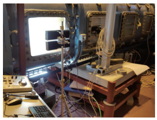 Figure 13 Experimental setup to measure propeller tip deflection on a cavitational tunnel (Maljaars et al. 2018)
The DIC technique identifies the blade deformation using the image's grey values. Several pictures of the blades were captured and filtered out to acquire highly accurate blade deformation values. Kawakita (2019) conducted an experimental study on metallic and resin flexible propellers to determine open water and cavitation performance in uniform and wake conditions. Initial research was conducted to better understand hydroelastic performance at various VA and RPM and to identify tip deformation. Later, pressure fluctuations and unsteady deformation during the astern mode were investigated. It was reported that a highly skewed propeller provided lower thrust and performance than the metal propeller during the operating regime, and significant differences in pressure coefficient were observed due to flexibility. The possibility of identifying the material properties of model scale from full scale was also reported. Ding et al. (2022a) and Ding et al. (2022b) reported monitoring blade deflection using FBG sensors. Open water experiments were conducted in a towing tank facility with different RPMs and advanced ratios. The inverse finite element method was used to obtain the deformation values using strain gauges.
3.3 Dynamic analysis-behind hull
Very limited studies are available on the performance analysis of CMPs in behind-hull conditions. Zondervan et al., (2017) measured the deformation of a five-bladed flexible propeller using the DIC technique behind the ship. The study aimed to establish the feasibility of using the DIC system to measure deformation during operating conditions. The study concluded that DIC had captured most of the blade surfaces with satisfactory levels of accuracy and suggested that optical fibre is more robust with greater accuracy in measurements. Grasso et al., (2019) carried out one of its kind investigation on estimating the full-scale deflection of CMP at several operating conditions. Using DIC, tip deflection, noise and tip cavitation patterns were observed and reported.
4 Numerical FSI models
On the surfaces of the propeller blades, pressure forces are developed due to rotation, which are then converted into a thrust force to propel the ship against resistance. Proper prediction of propeller pressure forces at each radial section (r/R) is highly important for estimating the propeller's performance. The inviscid and viscid numerical methods are widely adopted for predicting marine propeller performance, and the following section shall discuss the same in detail. These were coupled with numerical FEM methods for incorporating the hydroelastic effect.
The development of modern computer resources with high-fidelity techniques is a boon to all researchers and scientists. On several occasions in the past, the hydrodynamic and hydro-elastic performances of the marine propeller were analysed using numerical methods. BEM was widely used in inviscid coupling analysis to estimate the hydrodynamic behaviour of propellers since it was economically viable and reliable. In BEM, the discretisation happens only at the surface. Hence, the system of equations is limited. The inviscid fluid model is the ideal or non-viscous fluid model, where the viscosity term is zero. The forces exerted on the body's surface always conform to the boundaries, neglecting the shear component. On the other hand, viscous methods include the viscosity and turbulence effects that mimic the actual condition.
The BEM model is a 3D panel method model with a linear solution approach for the partial differential equations that require only surface discretisation. The meshes must be generated only on the surface or boundaries and not the whole system by considering only the boundary input data. It was initially developed in the early 1960s, considering the 3D geometric effect that can effectively capture the flow properties along the blade surfaces. BEM has evolved stronger than the original in recent decades, capable of handling wake inflow and rollup, cavitation, and free surface effect, and many research groups have significantly contributed to its developments.
In the case of composite propellers, where deformation affects performance, it is critical to consider turbulence, wake effects, and so on. Although the potential flow methods discussed above for computing hydrodynamic and hydroelastic studies are relatively less complicated, require fewer computational resources, are fairly accurate, and are capable of providing quicker results, it is still essential to consider the viscous effects because the propeller always operates in the viscous regime. Deformation will also affect the performance of composite propellers, and it is important to consider turbulence, wake effects, and so on. Thus, inviscid FSI analyses are replaced by viscous-based FSI solutions.
Numerous viscous CFD models are widely available in commercial and open-source formats such as RANSE, Hybrid RANSE-DES, LES, and DNS. The selection of models depends on the nature of the problem, boundary conditions, complexity, computation resources, and time. Figure 14 illustrates different turbulence models versus cost and accuracy. In most cases, the performance evaluation of marine propellers was based on the RANSE and URANSE models due to their computational efficacy, reliability, and cost. Table 1 provides the characteristics of BEM vs CFD.
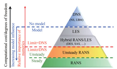 Figure 14 Selection of Turbulence models (Sagaut et al., 2013)Table 1 Difference between CFD and BEM
Boundary element method Computational fluid dynamics Discretisation of boundary Discretisation of volumes Neglects viscous effects Includes viscous effects Computationally cheap and quicker in providing the solution Computationally costlier and time-consuming in providing the solution The solution to the problem is written in terms of an integral formulation using Green's function for the particular system being investigated The solution is based on the conservation of mass, momentum and energy quantities. The partial differential equation/governing equations are discretised into a set of algebraic equations The total number of elements is less The total number of elements is more 4.1 Governing equation-Bem model
According to Pourmostafa and Ghadimi (2020), the boundary element method is based on potential flow, which depends on three main assumptions: incompressible, irrotational, and non-viscous flow. Accordingly, velocity is described as velocity potential ϕ(x, t) and should satisfy the three-dimensional Laplace equation.
$$ \nabla^2 \phi=0 $$ (4) The total potential velocity ϕ(x, t) can be written as a linear combination of fundamental potential functions such as sink/source, dipole and vortex, which could be computed on each cell (all types of cells are identified in the following). By applying Green's second identity, one could write the Laplace equation for any x located on the cell centre in the following form:
$$ 2 \pi \phi(x, t)=\int_s^s \phi(x, t) \frac{\partial \lambda}{\partial \boldsymbol{n}} \mathrm{d} S+\int_s^s \lambda \frac{\partial \phi(x, t)}{\partial \boldsymbol{n}} \mathrm{d} S $$ (5) where λ is defined as the fundamental solution for potential flow. In 3D formulation, λ = 1/r and n is the unit normal vector of the panel, pointing outward of the body and representing the distance between the source and field points. As a result, equation (2) can be written in the form of
$$ 2 \pi \phi(x, t)-\int_{s_w+s_z}^s \phi(y, t) \frac{\partial \frac{1}{r}}{\partial \boldsymbol{n}} \mathrm{~d} S+\int_{s_w+s_B}^s \frac{1}{r} \frac{\partial \phi(y, t)}{\partial \boldsymbol{n}} \mathrm{d} S $$ (6) 4.2 Governing equation-viscous fluid model
The Navier-Stokes equations explain the motion of viscous fluids through continuity and momentum equations, which take the form of partial differential equations as presented in equations 4 and 5. Here the continuity equation conserves mass, and the momentum equation is Newton's second law which states that mass times acceleration equals force.
$$ \nabla \cdot \boldsymbol{u}=0 $$ (7) $$ (\partial u / \partial t)=-\nabla \rho+v \nabla 2 \boldsymbol{u}+p \boldsymbol{F} $$ (8) where u is the velocity, ∂u/∂t is the time-dependent velocity, ν is the dynamic viscosity, ρ is the fluid density with p being the pressure and F being the force term. Combining the above equations forms a solution to solve the viscous flow, which is nothing but Navier Stokes equation as given below.
$$ (\partial u / \partial t)+p \nabla \cdot \boldsymbol{u}=-\nabla \rho+v \nabla 2 \boldsymbol{u}+p \boldsymbol{F} $$ (9) 4.3 Governing equation-solid
The general equation of the motion for the propeller blade in the solid model is defined as represented in equation (10):
$$ \boldsymbol{a} \ddot{{x}}+\boldsymbol{b} \dot{{x}}+\boldsymbol{c} {x}=F_T $$ (10) $$ F_T=F_P+F_{\text {Cent }}+F_{\mathrm{C}_\mathrm{o}} $$ (11) where ẍ, ẋ, x is acceleration, velocity, and displacement components. Furthermore, a, b, and c are the mass matrix, stiffness matrix and damping properties of the propeller. Equation (7) and (8) represents the total force FT acting on the propeller as the addition of hydrodynamic pressure (FP), centrifugal force (FCent), and forces due to the Coriolis effect (FCo), The structural behaviours of the propeller were computed by FEM numerical tool.
4.4 Inviscid coupling method
Georgiev and Ikehata (1998) were pioneers in reporting on numerical hydro-elastic investigations using inviscid methods under steady flow conditions. Previously, all hydroelastic investigations were conducted using simple and improved beam theory. The surface panel method was adopted for the different propellers to estimate the chord-wise distribution of stresses by static load testing. Ahead and astern modes were also thoroughly investigated. The study proposed a new method of investigating the hydroelastic effect and concluded that the effect of pitch distribution due to the bend-twist effect influences propeller performance. Since early 2000, Prof Y. L. Young has performed a significant amount of investigation on the hydro-elastic, cavitation, and optimisation studies for various lifting surface devices such as hydrofoils, propellers, and turbines.
Using the coupling algorithm, Young (2007b) and Young (2003) investigated the hydro-elastic behaviour of composite propellers under wake inflow. It was reported that the performance of composite propellers could be engineered using a hydro-elastic tailoring method with a bend-twist coupling effect. Also, the result showed that the performance of the propeller was better in wake conditions than in open water conditions. Young (2007a) performed a timedependent analysis for a cavitating propeller using the coupling algorithm to understand the moving cavities, pressure fluctuations and added mass effects. Liu and Young (2007) also proposed a design strategy for the proper design of composite propellers for equal or better performance than a metal propeller. The influence of material properties and the number of layers on the twisting rate was reported. A strong relationship was identified between the bend-twist deformation, pitch, and performance.
Young (2008) conducted a numerical FSI investigation on a composite marine propeller using BEM-FEM (Abaqus) for sub-cavitating and cavitating regimes. Hydrodynamics, cavitation pattern, deformation, and structural stress distribution were reported. The propeller's mode shapes were studied in both dry and wet conditions. The study recorded the importance of FSI analysis for the proper design of the composite propeller. Similar investigations on hydroelastic performance analysis and tailoring methods for self-adaptive propellers can be found in Liu and Young (2007), Motley et al. (2009), Motley and Young (2011), Young and Liu (2007).
Motley and Young (2012) compared the model and fullscale propeller along with the failure process for a composite marine propeller. The Froude number scale law must preserve the model's kinematic and dynamic similarities with the full scale. However, scaling the structural properties may be impossible in real conditions. On the other hand, the Mach number allowed using the same properties of the material for both scales. Also, Mach scaling is capable of predicting the material failure properties, but it underpredicts the gravitational forces. Hydro-elastic performance and effects of skew angles were predicted using a BEM-FEM code (Ghassabzadeh et al., 2013; Maljaars and Dekker, 2014). Four skew angles were investigated, and it was discovered that increasing the skew increased deformation and decreased performance. The effect of skew angle due to the hydrodynamic loading was studied using BEM-FEM methods in open water conditions. Figure 15 shows that with an increase in the skew angle, how the tip deflection is influenced by various advance coefficients.
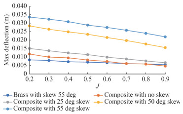 Figure 15 Maximum deformation for various composite skew angle (Ghassabzadeh et al., 2013)
Incorporating proper skew angle during the design stage has pronounced effective hydrodynamic and hydroelastic performance. Lee et al. (2014) and Mulle and Pécot (2017) performed BEM-FEM FSI analysis using panel code and Abaqus to estimate the blade deformation and strength. Natural frequencies for wet and dry modes were estimated. The results matched the literature and were found to follow a similar trend. Li et al.(2020, 2018a, 2017a) developed a numerical code to perform vibration and hydroelastic response analysis for estimating added mass and damping effect. Both one-way and two-way coupling approaches were performed. The code was similar to that (Young, 2008), but the difference is that both time- and frequency-dependent panel methods were incorporated into the solver. The model can be employed on the propeller rather than a camber surface, where thickness effects are considered.
Further information about the inviscid FSI coupling can be found in the literature (Kim et al., 2019; Maljaars et al., 2020; Radtke et al., 2020), where they developed LSTFEM coupling algorithms to estimate the hydro-elastic performance of the KP534 propeller. The open-water characteristics were estimated and verified with experimental results. Furthermore, using the structural solver, stress and deformation values were observed.
4.5 Viscid coupling methods-open water
Mulcahy et al. (2010) presented a method for hydroelastic tailoring of flexible propellers for spatially varying wake conditions to achieve improved performance over a rigid propeller. A CFD-ACE+ solver was adopted for hydrodynamics and SYSPLY for structural analysis. The model was validated with the literature and was in good agreement with the experimental results. A closed-form expression was developed to estimate the efficacy gain at design conditions for wake flows and reported that the gain is related to flexibility. He et al. (2012) and Vidya Sagar et al. (2013) carried out a 3D CFD-FEM coupled analysis based on the RANS equation for a seven- and six-bladed propeller to understand the hydro-elastic and modal characteristics. Han et al. (2015) investigated the hydro-elastic performance using the FSI method for KP458 and P5479 propellers. A partitioned co-simulation approach has been incorporated into the study to evaluate the stresses, deflection, and hydrodynamic pressure. The numerical results were in good agreement with the published results. FEM studies were performed for real FE and simple ply stack models for tapered beams.
Similar work to that mentioned above was carried out by Lee et al. (2017) for KVLCC2. Das and Kapuria (2016) examined four different propeller materials performances of glass and carbon lamina for full-scale conditions. The open-water performance was calculated using RANSE and deformation using first-order shear deformation theory. The effects of ply orientation, RPM, and thickness were examined along with the twist angle. It was found that the graphite-epoxy composite produced a 5.2 percent improvement. Kumar and Wurm (2015) conducted studies on a mixer blade with one and two-way FSI methods, producing large deformations. Different turbulence models were tested to identify the most suitable one for analysis, and SST Gamma–Theta was found to be the best one for turbulence model. Among them, the two-way FSI was found to be accurate for transient simulations. Nouri et al. (2018) studied the effects of the camber ratio on the hydro-elastic performance of ducted propellers in the presence of wake. A CFD-FEM-based coupling method was used on eight different propeller models with seven blades to estimate efficacy, deformation, hydrodynamic pressure, and frequencies. With the camber ratio, the thrust also increases at the operating regime, and maximum efficiency is achieved at a camber ratio (f/c) of 1.5 percent. An et al.(2020, 2019) investigated the hydro-elastic performance of a composite ducted propeller using two-way FSI simulations and modal analysis. The twist angle was found to be an influencing factor of efficiency, where it is lower at higher J and higher at lower J. Tip clearance between the duct and propeller plays a significant role in performance, where an increase in the gap leads to better efficacy. An extension of the above work was carried out by Han et al. (2022) with a different lamination scheme. Using CFD–FEM coupling method, hydro-elastic simulations were carried out in explicit coupling method using commercial CFD-FEM software by (Kumar et al., 2021). The system was robust, and reliable results were estimated. Two geometrically ideal steel and carbon fibre propellers were chosen to operate at various advanced coefficients. The open water conditions were mimicked numerically, and it was found that the open water performance has been improved at design conditions, and Figure 16 depicts the same.
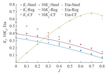 Figure 16 FSI analysis of B-series propeller and validation with regression analysis for steel and CFRP materials
Hussain et al. (2021) identified that the twisting moment on the propeller is influenced by pitch and skew. Initially, CFD analysis was carried out for rigid propellers, and the geometric pitch was introduced to identify the changes in performance. At lower J, the lower pitch improved efficiency. The study also revealed that the positive pitching moment at design time has a better self-adapting nature. Ashok et al. (2020) studied the vibration of composite marine propellers using numerical simulations.
Fuentes et al. (2022) performed a two-way FSI analysis using commercial CFD-FEM software for the P1790 propeller in open water conditions. Hydrodynamic and hydroelastic characteristics were evaluated and compared with experimental results. Stresses and deformation patterns were observed and reported in this study. The global hydrodynamic performance of passively bending propellers has improved due to their hydro-elastic characteristics. Hence, from the above literature, it is suggested that to capture the coupled effect of deformation of the boundary of propellers and the associated viscous effects, the two-way coupled viscous FSI analysis is a better model for predicting hydroelastic effects on flexible propellers.
4.6 Viscid coupling methods-behind hull
Numerically simulating the self-propulsion shall be tremendously costlier in terms of resource utilisation and simulation time. Several times they are approximated using the virtual disk method for quicker and more reliable results. However, for CMPs, it is necessary to use the blade profile to estimate the exact performance prediction. Han et al. (2015) investigated the behind hull performance of a composite KP458 propeller using the sliding mesh method and moving reference frame method for predicting the unsteady deformation under wake. Ashok and Vijayakumar (2022) studied self-propulsion characteristics of composite marine propellers using numerical simulations for a B-series propeller at operating conditions in calm water. The deformation and stresses were reported to be lesser than in open water.
4.7 Example-numerical two-way FSI
A numerical simulation study was carried out to predict the hydroelastic performance of a flexible marine propeller using co-simulation studies for a Potsdam Propeller Test Case P1790 propeller operating at open water conditions. A partitioned coupling method based on RANS equationbased CFD-FEM coupling was used to estimate the hydrodynamic and hydroelastic performance analysis. The results were validated with the experimental studies conducted by (Fuentes et al., 2022). Figure 17 illustrates the mesh generated on the propeller surface. Figure 18 depicts the axial displacement vs advance ratio. The numerical and experimental results were in good agreement. Thus, the numerical solver is verified and can be widely used for further FSI applications. For more information about the numerical model, refer to Kumar et al.(2021).
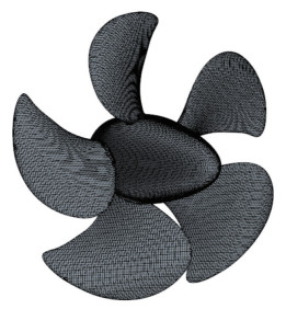 Figure 17 Propeller mesh
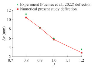 Figure 18 Deformation at axial direction
5 Other parameters influencing design of composite propellers
5.1 Cavitation studies
Cavitation is a multiphase phenomenon that occurs when the vapour pressure of water falls below that of the atmosphere pressure. As the propeller rotates, pressure discrepancies occur between the face and back sides, generating thrust. In some operating conditions, the vapour pressure reduces, and at this moment, the water will start boiling, create bubbles (below the actual boiling point), and change its state from liquid to vapour. These bubbles will collide on the propeller surface and/or with one another, resulting in massive impact loads. There are different types of cavitation based on their occurrence: sheet, root, bubble, hub and tip vortex, leading and trailing edge cloud, and propeller hull vortex. Figure 19 explains some of the common types of propeller cavitation. They cause wear and tear, fatigue load, and blade erosion on the propeller surface, leading to poor hydrodynamic performance and breakage. Thus, it is important to maintain a cavitation-free regime throughout the propeller's operation; hence, the design, development, and material selection play a vital role in thrust generation and efficacy.
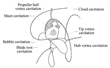 Figure 19 Cavitation on a marine propeller (ITTC, 2019)
To avoid the occurrence of cavitation during operating Figure 17 Propeller mesh conditions, it is essential to understand bubble formation and its associated dynamics. Hence, some recent literature on bubble dynamics is discussed here. Zhang and Ni (2014) studied the 3D model of a bubble with viscous effects, which was explored using a BEM. The 3D numerical model developed was compared with axisymmetric ones, and analytical results agreed. The study reported that the jet velocity is reduced due to viscous dissipation. Zhang et al. (2015) studied the splitting of toroidal bubbles near the rigid surface using the boundary integral method generally performed via experiments. The researchers observed several new phenomena during the study, such as the sideways jet moving on a sub-bubble surface, which would cause more splits of the splash film into droplets. Zhang et al. (2017) studied the underwater explosion of complex bubbles using a 3D fully coupled potential theory. The pressure distribution in the flow field is calculated with the Bernoulli equation, where the partial derivative of the velocity potential in time is calculated using the boundary integral method. An experiment was conducted to validate the numerical model and explore the strain responses of the stiffened plates. Li et al. (2017a) studied bubble-sphere interaction near a rigid plate using experimental and numerical methods. The standoff parameter was reported to decrease with an increased coupling effect. The interactions were classified into weak strong, and intermediate cases, and results were discussed. Li et al. (2018a) reported that strong interaction phenomena happened between the elastic sphere and the cavitation bubble. It was identified that the a small liquid jet was developed during early expansion stage away from its boundary. Zhang et al. (2023) proposed a unified theory for bubble dynamic equations which can simulate considering the effect of boundary, bubble interaction, ambient flow field, gravity, bubble mitigation etc. Furthermore, the theory was validated with the experimental data and found to be in good agreement. The proposed equation derived considering bubble oscillation, bubble mitigation and bubble velocity and pressure field. Developing high-fidelity models is considered a boon to the hydrodynamic community where the bubble oscillations, mitigation and collapse are identified. These equations are highly valued in the initial design stages for the cavitation of propellers and other turbomachines. The propeller cavitation prediction models shall be applied to the CMPs to understand the effect of bubble formation, dynamics, movement under viscous flows and explosion.
In 1998, Gowing et al. (1998) illustrated experimental data for two hydroelastically tailored composite elliptic hydrofoils that were designed to undergo twists under the design load. They reported that tip deflections reduced the effective angle of attack, which in turn delayed cavitation inception due to reduced loading near the tip region; however, the overall drag and lift remained unchanged.
Young (2003) developed a 3D BEM code to predict the hydrodynamic characteristics of partial and fully submerged propellers, and later it was extended to perform coupling analysis with FEM. The numerical results were found to be in good agreement with the experimental results. Gas and sheet cavities were modelled and allowed to impend on both sides of the blade surfaces, and open water performance was analysed. Four different propellers, such as Propeller 4383, 3768, 4407, and M841B, were subjected to cavitation testing, and the results were compared with experiments. The coupled effects, however, were not reported.
According to Young et al. (2009), cavitation occurs due to an increased ship's RPM at a fixed depth. The cavitation tunnel model test for rigid propellers was simpler because the variation was only on the P0, but for composite propellers, both P0 and RPS must be changed. They used BEMFEM coupling to perform cavitation studies and identified performance under two test scenarios. One has fixed speed and RPS at constant advance ratio, and the other has variable speed and RPS at constant advance ratio. In the first case, the adaptive propeller showed a decreased pitch angle and reduced face cavitation. This, in turn, has increased the KT, KQ, and η0. In the second scenario, however, the adaptive propeller performed poorly. This is due to the lower deflection of the pitch angle than that of a rigid propeller. Young and Liu (2007) and Young (2007b) used the BEM-FEM coupling method to predict the time-dependent responses of cavitating propellers and validated their predictions with experiments. Deformation, stresses, and modal frequency were analysed for four propellers with varying skew angles. As the skew increased, so did the stresses and the natural frequency. Motley et al. (2009); Motley and Young (2011) investigated the performance of NAB and CFRP propellers under steady and unsteady conditions. They reported that the CFRP propeller had altered its pitch angle, due to which a significant decrease in cavitation volume compared to the NAB propeller was observed. Hong et al. (2017) conducted an open-water and cavitation study on the same series of propellers with modified geometry. At 0.7r/R, the cavitation number of the composite propeller was much higher than that of the rigid propeller, proving that the cavitation occurrences are delayed due to flexibility.
Yamatogi et al. (2011) conducted an experimental investigation on composite propellers to understand the cavitation erosion phenomenon. CFRP, Aramid, and NAB propeller materials were considered. Using an ultrasonic transducer device, pressure fluctuations were created on the specimens to recreate the cavitation. It was observed that Aramid fibre showed the strongest resistance, followed by CFRP and GFRP. Sajedi and Mahdi (2022) calculated the effect of cavitation on the hydroelastic behaviour of a B-series propeller in open-water conditions. The formation of cavitation reduced the deformation and stress levels in comparison with wetted flows. It was reported that the cavitation flow had lower performance characteristics than wetted flow at a constant advance ratio, and a similar pattern of cavitation volume was observed between the metal and flexible propellers. Thus, from a bird's eye view, it can be concluded that the performance of flexible propellers excels in cavitation flow by varying the pitch angle due to deformation.
5.2 Acoustics
The URN in the ocean environment has been found to have increased by up to 20 dB in recent years due to increased marine traffic around the globe. It is highly unfortunate that the marine ecosystem, flora and fauna, have been significantly disturbed, and several of them have become endangered. Both surface and underwater vessels' marine propellers are key contributors to the URN during their voyage or operation. Numerous global research initiatives are working to achieve long-term goals in reducing propeller noise by modifying geometry, material, and operating regime. However, only limited literature is available on acoustic measurements of composite propellers. Zhang and Ma (2018) mentioned that the composite propeller reduces the noise by up to 5 dB and reduces fuel consumption by up to 15 percent.
Paik et al. (2013) investigated the propeller and background noise levels using experimental methods at three frequency bands, including the blade pass frequency band. The acoustic properties of two glass fibre propellers and one carbon fibre propeller were evaluated. The noise levels were proportional to the thrust and increased at tip vortex cavitation. The glass-epoxy blade provided lower noise levels, and proper hydroelastic tailoring is required to improve the efficacy. Rama et al. (2021) estimated the SPL of DTMB 4119 using two-way FSI and FW-H equations at design conditions for a frequency range of 0 ‒ 1 000 Hz, and they discovered an exponential decline in decibel levels for composite propellers due to damping properties. Kim et al. (2022) compared the SPL of rigid and composite propellers in a non-cavitating regime and found that there were not enough differences between them. However, a notable difference was found under the cavitation flow conditions. Due to the lack of data on the composite propeller, it is difficult to draw any conclusions about its performance. However, from the basic study, a reduction in the noise level was observed, and there is a need for further investigation into the noise and vibration characteristics of composite propellers in the future.
5.3 Effect of layer sequences
In most cases, the propellers were manufactured using homogeneous and isotropic materials, such as metals or alloys, where the structural properties were independent of direction. Therefore, the casting process was adopted for propeller manufacturing, where molten metal is poured into the mould and allowed to cool. However, in the case of composite materials, the fibre orientation defines the strength of the material, and hence the stacking sequence should be designed with great care. The order in which the plies are oriented with reference to the laminate coordinate system defines it as a unidirectional, symmetric, or antisymmetric sequence. Figures 20(a) ‒ 20(b) illustrate the unidirectional and symmetric sequence of plyorientation, respectively.
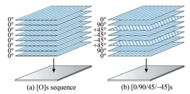 Figure 20 Stacking sequence orientation
In unidirectional layers, the maximum strength of the composite shall be only along the 0° orientation, and the strength shall be in different directions in a symmetric orientation. Hence, a systematic calculation of hydro-elastic tailoring is required to achieve a propeller with the right strength characteristics to withstand the hydrodynamic loads with improved performance at operating conditions; otherwise, the propeller may deform extensively and break, especially near the root section.
Lin and Lin (1997) and Lin et al. (2010) studied the effects of stacking sequence and nonlinear effect on an MAU series 3‒60 blade to understand the hydroelastic performance with balanced and unbalanced stacking sequence using the FEM method. They reported that the stacking sequence had an influence on the performance improvement at J less than 0.5; however, no influence was found beyond the same. Lin and Lee (2004) performed optimisation studies to improve the operating range of composite propellers. An optimising genetic algorithm was used to identify the best stacking sequences. However, the performance was not improved with the original geometry; hence, a pre-deformed geometry was adopted, which outperformed the metal propeller. Lee and Lin (2004) modified the standard genetic algorithm with local improvements to optimise the stacking sequence, which was applied to a composite propeller. It was reported that there was performance improvement, and the method was suitable for optimising the ply sequence for any composite applications. Motley et al. (2009) and Blasques et al. (2010) carried out research on identifying the optimum material stacking to improve propulsion efficiency. Li et al. (2013) numerically studied the FSI analysis of the VP1304 model propeller. Three stacking sequences were used and compared for the propeller's hydrodynamic and structural responses. The deformation was discovered to be directly proportional to the thrust forces obtained through proper hydro-elastic tailoring, and it is expected to improve performance. He et al. (2012) investigated and analysed harmonic forces and moments, discovering that they are lower for composite propellers than metal propellers. According to the study, the stacking sequence improved the propeller's performance by up to 70.6 percent. Hong et al. (2014) conducted optimisation studies for a composite propeller using the RANSE–FEM method. A pre-twist was identified for the composite propeller and tested for its performance. The optimisation study took a look at a specific stacking sequence and discovered that performance has improved. Prini et al. (2017) studied the effects of stacking, stud, and advance coefficients on the propeller's deflection parameter. The study was carried out for four sequences, three-stud geometry, and various advance coefficients. Dynamic pressure was calculated by UPCA91 software and applied to the propeller. The blade deflection varied at different chord lengths and for different stacking sequences. For example, the tip deformation for the quasi-isotropic and cross-ply sequences is lower than for the unidirectional one. Mulle and Pécot (2017) created a coupling algorithm for FSIbased adaptive propeller and turbine analysis. Using PROCAL and FEA, the blade deformations were studied for three layup sequences. Since the algorithm was at the initial development stage, no major results or conclusions were discussed; however, it was assured that the algorithm was user-friendly and a better tool for the initial design.
Lin et al. (2005) studied the effects of layup, failure modes, and tension and compression levels for fibre and matrix, along with delamination. Using LST and FEM, the analysis was carried out on a plate and later on a composite propeller. A balanced and unbalanced symmetric stacking sequence was considered when the strength of the propeller was analysed. Also, there were delaminations near the leading and trailing edge sections with one set of sequencing. The effects of stacking sequences on the performance of an MAU propeller were studied by Lin et al. (2010). Symmetric balance and unbalanced stacking sequences were used to identify its influence on thrust and pitch distribution. Yamatogi et al. (2011) carried out experiments to investigate the CFRP material coupons with two layup sequences. Tensile, bending, and vibration tests were performed on the two sequences, and the results showed that the values were comparable. Kim et al. (2022) studied the performance of an underwater vehicle's composite propeller, including the effect of stacking, by the CFD-FEM method. Out of five models, one was manufactured, and experiments were performed and compared with its rigid counterpart. The rest of the models were simulated numerically using FEM. It was observed that composite propellers had undergone significant deformation, which altered the pitch of the propeller. Han et al. (2022) have performed two-way FSI studies on ducted propellers and various stacking sequences. Three different schemes with glass and carbon fibre material were considered numerically for the analysis. They concluded that the change in the stacking sequence led to a complex change in propeller performance, and based on the operating conditions, one scheme was chosen to be most suitable for optimising performance.
6 Future scope and directions
Many researchers in the past have made several attempts to fully explore the performance of composite propellers using numerical and/or experimental methods. However, there were several limitations, shortfalls, constraints, and restrictions in exploring its complete performance, and the scope for further research work is still on. In experimental investigations, the methods for the estimation of deformation have to be developed in more robust and economical ways. Since the model is a scaled version of the prototype, the extrapolation of model deformation to prototype scale must be established, like hydrodynamic parameters. DIC and high-speed cameras with stroboscope facilities are proven methods for deflection measurements; however, they require huge initial investments and skilled personnel for operation and maintenance. More research is to be focused on developing deflection measurement techniques and monitoring systems to predict hydroelastic characteristics accurately. There is a lack of facilities to measure underwater deflection in a towing tank facility. With respect to cavitation, more detailed investigations of CMPs are required to suggest the delay in inception speed strongly. Delamination studies must be conducted for better hydroelastic tailoring in case of damage due to fatigue and cavitation. The change in the vortex pattern shall be compared with the rigid counterpart for the improvement of blade design.
Self-propulsion characteristics of CMPs must be thoroughly analysed with multi-axis sensors for the efficient understanding of hydroelastic behaviour. An effective understanding of the hull's wake influence on the propeller shall serve as input for the initial design process. Also, the selection of the blade's profile, pre-deformation, and strength aspects may be decided at an early stage. Apart from Maritime Research Institute Netherlands-MARIN, no literature reported the self-propulsion model test of composite propellers under various operating regimes. The vibration profile on CMPs needs keen research on model-scale and fullscale to explore damping characteristics.
There is also necessary to understand the noise characteristics of composite propellers in open water and wake conditions. The passive deformation modifies the propeller's wake characteristics and, more predominately, at the tip, which could be a focus of study for cavitation, vibration, and noise. It aids in understanding and comprehensively concludes the implementation of such propellers for naval vessels. In numerical analysis, high-fidelity methods should be adopted to estimate the accuracy of performance prediction under uniform and non-uniform conditions. The effect of stacking sequence requires additional serious investigation to fully explore the structural regime of composite material. As the propeller works mainly on the offdesign loads, the composite material tailoring shall incorporate all design criteria to withstand the increased load; otherwise, due to larger pitch variation and heterogeneous wake inflow, there may be chances of the propeller stalling or breaking. Also, the investigation of composite propellers under various mission-based design conditions shall contribute to comprehensively understanding the composite propellers in all three aspects (hydrodynamic, structural, and acoustics). There is a need to identify the proper turbulence model, vortex analysis, blade deformation, and stress parameters in more detail using appropriate solution methods to match the real conditions. As cavitation is a dynamic phenomenon, the need to understand various operating regimes and their formation on blade surfaces needs to be quantified more precisely, and only the hydrodynamic parameter may not suffice. Shape optimisation and hydroelastic tailoring are some studies that need in-depth investigations to understand the advantages and constraints of composite propellers.
7 Conclusions
In this article, an attempt is made to provide a succinct review of the performance and limitations of composite marine propellers:
1) The study in the initial parts deals with propeller design, material challenges, the need for alternative materials, and the evolution of composite materials. Discussions were held on hydroelastic coupling, including the one-way and two-way approaches.
2) In the experimental studies, static and dynamic openwater tests were carried out to identify the CMPs' performance characteristics. The dynamic analysis mimics the actual operating condition identifying both hydrodynamic and structural properties in test facilities. Around 31.3 percent and 22 percent of the literature show that cavitation tunnel and towing tank were incorporated, respectively. However, manufacturing precise small-scale models and accessing the facilities are highly tedious and uneconomical. The exploration of results in behind hull or wake conditions is still underway.
3) The numerical investigations carried out in the past consist of one-way and two-way coupled analysis under viscid and inviscid conditions. Around 43 percent of the literature has incorporated the viscous effect during the analysis for hydroelastic characteristics. In most of the studies, composite propellers' hydrodynamic performance was better than metallic propellers, mainly due to their flexible nature, which leads to blade deformation. Like the experimental method, the researchers are still studying the exploration of results behind hull or wake conditions and more research in this area is required to understand off-load performances.
4) The effects of cavitation and stacking sequence on the performance of composite propellers were discussed. The pressure distribution on the blade surfaces is highly modified due to the change in blade profile. It was concluded that the cavitation inception speed was delayed due to blade deflection and therefore reduced cloud formation.
5) The structural properties of composite propellers highly depend on the stacking sequence, which shall aid in developing an appropriate blade required for the particular operating condition with maximum strength characteristics. Hydroelastic tailoring is highly recommended at the initial stages of blade design, which shall aid in developing a better blade profile. The stress patterns, vibration, and fatigue characteristics of CMPs need an in-depth exploration.
6) The acoustic characteristics of composite materials show better performance than their metallic counterparts under operating conditions; however, the same needs to be fully explored in the future.
Hence from the above conclusion, the CMPs are found to be a better replacement for metallic propellers and a significant research exploration is recommended to comprehend the performance of CMPs in various zones and horizons. It is also predicted that the CMPs may significantly contribute to IMO's decarbonising goals by reducing greenhouse gases with superior performance to traditional propellers.
Nomenclature BEM Boundary element method CFRP Carbon fiber-reiforced plastic CFD Ccomputational fluid dynamics CMP Composite marine propeller DES Detached eddy simulation DIC Digital image correlation DNS Direct numerical solution DTMB David taylor model basin DTNSRDC David W. Taylor Naval Ship Research and Development Center EEDI Energy efficiency design index EEXI Energy efficiency existing ship index EV Electric vehicile FBG Fibre bragg grating FEM Finite element merhod FSI Fluid-structure interaction FVM Finite volume method FW-H Ffowcs williams-hawkings GHG Green huse gas GT Gross tonnage LBM Lattice boltzmann melthod IMO International maritime oraganisation LES Large eddy simulation LST Lifting sufrafce theory NAB Nickel aluminium bronze PVC Polyvinyl chloride RANSE Reynolds-averaged navier-stokes equation RPM Revolution per minute RPS Revolution per second SAS Scale adaptive simulation SPL Sound pressure level URN Underwater radiated noise d Blade diameter (m) E Youndes modulus (GPa) G Rigidity modulus (GPa) T Thrust (N) Q Torque (N⋅m) υ Poison ratio J Advance ratio Va/VA Advance velocity (m/s) ηo Open water efficiency KT Thrust coefficient KQ Torque coefficient υ Kinematic viscosity (N⋅s/m2) μ Dynamic viscosity (Pa·s) ρf Density of water (fluid) (kg/m3) ρs Density of material (solid) (kg/m3) p Pressure (N/m2) P0 Reference pressure (N/m2) Δt Time step (s) Competing interest The authors have no competing interests to declare that are relevant to the content of this article. -
Figure 1 IMO suggestion for decarbonisation (International Maritime Organisation, 2019)
Figure 2 Overview of the sections and their significance
Figure 3 Challenges associated with conventional propeller materials
Figure 4 Types of synthetic or man-made composite material
Figure 5 Methods of performance analysis CMPs
Figure 6 Methods of performance analysis CMPs
Figure 7 One-way coupling method
Figure 8 Two-way coupling method
Figure 9 FSI coupling method
Figure 10 Segmented loading for static deflection analysis (Kumar et al., 2019)
Figure 11 A finished composite propeller blade (Chen et al., 2006)
Figure 12 DTNSRDC 4498 composite propeller (Lin et al., 2009)
Figure 13 Experimental setup to measure propeller tip deflection on a cavitational tunnel (Maljaars et al. 2018)
Figure 14 Selection of Turbulence models (Sagaut et al., 2013)
Figure 15 Maximum deformation for various composite skew angle (Ghassabzadeh et al., 2013)
Figure 16 FSI analysis of B-series propeller and validation with regression analysis for steel and CFRP materials
Figure 17 Propeller mesh
Figure 18 Deformation at axial direction
Figure 19 Cavitation on a marine propeller (ITTC, 2019)
Figure 20 Stacking sequence orientation
Table 1 Difference between CFD and BEM
Boundary element method Computational fluid dynamics Discretisation of boundary Discretisation of volumes Neglects viscous effects Includes viscous effects Computationally cheap and quicker in providing the solution Computationally costlier and time-consuming in providing the solution The solution to the problem is written in terms of an integral formulation using Green's function for the particular system being investigated The solution is based on the conservation of mass, momentum and energy quantities. The partial differential equation/governing equations are discretised into a set of algebraic equations The total number of elements is less The total number of elements is more Nomenclature BEM Boundary element method CFRP Carbon fiber-reiforced plastic CFD Ccomputational fluid dynamics CMP Composite marine propeller DES Detached eddy simulation DIC Digital image correlation DNS Direct numerical solution DTMB David taylor model basin DTNSRDC David W. Taylor Naval Ship Research and Development Center EEDI Energy efficiency design index EEXI Energy efficiency existing ship index EV Electric vehicile FBG Fibre bragg grating FEM Finite element merhod FSI Fluid-structure interaction FVM Finite volume method FW-H Ffowcs williams-hawkings GHG Green huse gas GT Gross tonnage LBM Lattice boltzmann melthod IMO International maritime oraganisation LES Large eddy simulation LST Lifting sufrafce theory NAB Nickel aluminium bronze PVC Polyvinyl chloride RANSE Reynolds-averaged navier-stokes equation RPM Revolution per minute RPS Revolution per second SAS Scale adaptive simulation SPL Sound pressure level URN Underwater radiated noise d Blade diameter (m) E Youndes modulus (GPa) G Rigidity modulus (GPa) T Thrust (N) Q Torque (N⋅m) υ Poison ratio J Advance ratio Va/VA Advance velocity (m/s) ηo Open water efficiency KT Thrust coefficient KQ Torque coefficient υ Kinematic viscosity (N⋅s/m2) μ Dynamic viscosity (Pa·s) ρf Density of water (fluid) (kg/m3) ρs Density of material (solid) (kg/m3) p Pressure (N/m2) P0 Reference pressure (N/m2) Δt Time step (s) -
An X, Song B, Xia H, Ding Y, Jin Z, Lessard L (2019) Coupled numerical simulation and modal analysis of composite ducted propeller. Sixth International Symposium on Marine Propulsors, Rome, 1–8 An X, Wang P, Song B, Lessard L (2020) Bi-directional fluid-structure interaction for prediction of tip clearance influence on a composite ducted propeller. Ocean Eng. 208: 107390. https://doi.org/10.1016/j.oceaneng.2020.107390 Ashok KS, Anantha SV, Vijayakumar R (2020) Numerical study on the performance analysis and vibration characteristics of flexible marine propeller. In International Conference on Offshore Mechanics and Arctic Engineering, Florda, 84379. https://doi.org/10.1115/OMAE2020-18538 Ashok KS, Vijayakumar R (2022) Numerical study on the performance of a composite marine propeller in self-propulsion condition using the FSI algorithm. Ocean. Conf. Rec. 1–6. DOI: 10.1109/OCEANSChennai45887.2022.9775126 Blasques JP, Berggreen C, Andersen P (2010) Hydro-elastic analysis and optimisation of a composite marine propeller. Mar. Struct. 23: 22–38. https://doi.org/10.1016/j.marstruc.2009.10.002 Chen BYH, Neely SK, Michael TJ, Gowing S, Szwerc RP, Buchler D, Schult R (2006) Design, fabrication and testing of pitch-adapting (Flex) propellers. Paper presented at the SNAME 11th Propeller and Shafting Symposium, Williamsburg, Virginia, USA, 1–12. https://doi.org/10.5957/PSS-2006-08 Colclough WJ, Russell JG (1972) The development of a composite propeller blade with a carbon fibre reinforced plastics spar. Aeronautical Journal-New Series 76(733): 53–57. DOI: 10.1017/S0001924000042408 Das HN, Kapuria S (2016) On the use of bend-twist coupling in full-scale composite marine propellers for improving hydrodynamic performance. J. Fluids Struct. 61: 132–153. https://doi.org/10.1016/j.jfluidstructs.2015.11.008 Ding G, Jiang N, Gao X, Wang F, Wu X (2022a) Deformation monitoring of propeller underwater operation based on fiber optic grating sensing network. Ocean Eng. 264: 112308. https://doi.org/10.1016/j.oceaneng.2022.112308 Ding G, Yan X, Gao X, Zhang Y, Jiang S (2022b) Reconstruction of propeller deformation based on FBG sensor network. Ocean Eng. 249: 1–9. https://doi.org/10.1016/j.oceaneng.2022.110884 Dubbioso G, Muscari R, Ortolani F, Di Mascio A (2022) Numerical analysis of marine propellers low frequency noise during maneuvering. Part II: Passive and active noise control strategies. Appl. Ocean Res. 106: 102461. https://doi.org/10.1016/j.apor.2022.103201 Fuentes D, Cura Hochbaum A, Schulze R (2022) Numerical and experimental fluid - structure interaction analysis of a flexible propeller. Sh. Technol. Res. 1–11: 163–173. https://doi.org/10.1080/09377255.2022.2115241 Georgiev DJ, Ikehata M (1998) Hydroelastic effects on propeller blades in steady flow. J. Soc. Nav. Archit. Japan 1–14: 116046253. https://doi.org/10.2534/jjasnaoe1968.1998.184_1 Ghassabzadeh M, Ghassemi H, Saryazdi MG (2013) Determination of hydrodynamics characteristics of marine propeller using hydroelastic analysis. Brodogradnja 64: 40–45 Ghose PJP, Gokarn RP (2015) Basic ship propulsion. KW Publisher Pvt Ltd, New Delhi, India, 216–217 Gowing S, Coffin P, Dai C (1998) Hydrofoil cavitation improvements with elastically coupled composite materials. Paper presented at the SNAME 25th American Towing Tank Conference, Iowa, USA, 425–429. https://doi.org/10.5957/attc-1998-019 Grasso N, Hallmann R, Scholcz T, Zondervan GJ, Maljaars P, Schouten R (2019) Measurements of the hydro-elastic behaviour of flexible composite propellers in non-uniform flow at model and full scale. Sixth International Symposium on Marine Propulsors, Rome, Itly, 1–10 Grigoropoulos GJ, Campana EF, Diez M, Serani A, Gören O, Sariöz K, Danisman DB, Visonneau M, Queutey P, Abdel-Maksoud M, Stern F (2017) Mission-based hull form and propeller optimisation of a transom stern destroyer for best performance in the sea environment. 7th Int. Conf. Comput. Methods Mar. Eng., 83–94 Han S, Lee H, Min Churl S, Chang BJ (2015) Investigation of hydro-elastic performance of marine propellers using fluid-structure interraction analysis. ASME International Mechanical Engineering Congress and Exposition, IMECE2015, Houston, Texas, 1–9. https://doi.org/10.1115/IMECE2015-51089 Han S, Wang P, Jin Z, An X, Xia H (2022) Structural design of the composite blades for a marine ducted propeller based on a two-way fluid-structure interaction method. Ocean Eng. 259: 111872. https://doi.org/10.1016/j.oceaneng.2022.111872 Hara Y, Yamatogi T, Murayama H, Uzawa K, Kageyama K (2011) Perfomrance evaluation of composite marine propeller for a fishing boat by fluid-structure interaction analysis. The 18th International Conference on Composites Materials, Jeju Island, Korea, 1–6 He XD, Hong Y, Wang RG (2012) Hydroelastic optimisation of a composite marine propeller in a non-uniform wake. Ocean Eng. 39: 14–23. https://doi.org/10.1016/j.oceaneng.2011.10.007 Hong Y, Hao LF, Wang PC, Liu WB, Zhang HM, Wang RG (2014) Structural design and multi-objective evaluation of composite bladed propeller. Polym. Polym. Compos. 22: 275–282. https://doi.org/10.1177/096739111402200308 Hong Y, Wilson PA, He XD, Wang RG (2017) Numerical analysis and performance comparison of the same series of composite propellers. Ocean Eng. 144: 211–223. https://doi.org/10.1016/j.oceaneng.2017.08.036 Huang Z, Xiong Y, Yang G (2016) Fluid-structure hydroelastic analysis and hydrodynamic cavitation experiments of composite propeller. Proceedings of the International Offshore and Polar Engineering Conference, Rhodes, Greece, 441–447 Hussain M, Abdel-Nasser Y, Banawan A, Ahmed YM (2021) Effect of hydrodynamic twisting moment on design and selection of flexible composite marine propellers. Ocean Eng. 220: 108399. https://doi.org/10.1016/j.oceaneng.2020.108399 International Maritime Organisation (2019) Citing electronic sources of information. International Maritime Organisation. Available from https://www.imo.org/en/MediaCentre/HotTopics/Pages/Cutting-GHG-emissions.Aspx [Accessed on Apr. 11, 2023] ITTC (2019) Citing electronic sources of information International towing tank conference ITTC. Available from https://ittc.info/media/8372/index.pdf [Accessed on Apr. 11, 2023] Kawakita C (2019) An experimental study on hydrodynamic performance of flexible composite model propellers. 6th International Symposium on Marine Propulsors, Rome, Italy, 247595999 Kim JH, Ahn BK, Ruy WS, Kim GD, Lee CS (2019) Numerical prediction of hydroelastic performance of the flexible propeller. Int. J. Offshore Polar Eng. 29(3): 339–346. https://doi.org/10.17736/ijope.2019.mk64 Kim JH, Lee H, Kim SH, Choi HY, Hah ZH, Seol HS (2022) Performance prediction of composite marine propeller in non-cavitating and cavitating flow. Appl. Sci. 12: 5170. https://doi.org/10.3390/app12105170 Kumar A, Lal Krishna G, Anantha Subramanian V (2019) Design and analysis of a carbon composite propeller for podded propulsion. Lecture Notes in Civil Engineering. Springer, Chennai, 203–215. https://doi.org/10.1007/978-981-13-3119-0_13 Kumar A, Vijayakumar R, Subramanian V (2021) Numerical fluid-structure interaction analysis for a flexible marine propeller using co-simulation method. Int. J. Marit. Eng. 163: 83–92. https://doi.org/10.5750/ijme.v163ia2.759 Kumar J, Wurm FH (2015) Bi-directional fluid-structure interaction for large deformation of layered composite propeller blades. J. Fluids Struct. 57: 32–48. https://doi.org/10.1016/j.jfluidstructs.2015.04.007 Lee H, Song MC, Han S, Chang BJ, Suh JC (2017) Hydro-elastic aspects of a composite marine propeller in accordance with ply lamination methods. J. Mar. Sci. Technol. 22: 479–493. https://doi.org/10.1007/s00773-016-0428-4 Lee H, Song MC, Suh JC, Chang BJ (2014) Hydro-elastic analysis of marine propellers based on a BEM-FEM coupled FSI algorithm. Int. J. Nav. Archit. Ocean Eng. 6: 562–577. https://doi.org/10.2478/IJNAOE-2013-0198 Lee YJ, Lin CC (2004) Optimised design of composite propeller. Mech. Adv. Mater. Struct. 11: 17–30. https://doi.org/10.1080/15376490490257639 Li G, Li W, You Y, Yang C, Hu T (2013) Study on fluid-structure interaction characteristics of composite marine propeller. Proceedings of the International Offshore and Polar Engineering Conference. International Society of Offshore and Polar Engineers (ISOPE), Alaska, USA, 554–559 Li J, Qu Y, Hua H (2017a) Hydroelastic analysis of underwater rotating elastic marine propellers by using a coupled BEM-FEM algorithm. Ocean Eng. 146: 178–191. https://doi.org/10.1016/j.oceaneng.2017.09.028 Li J, Qu Y, Zhang Z, Hua H (2020) Parametric analysis on hydroelastic behaviors of hydrofoils and propellers using a strongly coupled finite element/panel method. J. Mar. Sci. Technol. 25: 148–161. https://doi.org/10.1007/s00773-019-00638-z Li J, Rao Z, Su J, Qu Y, Hua H (2018a) A numerical method for predicting the hydroelastic response of marine propellers. Appl. Ocean Res. 74: 188–204. https://doi.org/10.1016/j.apor.2018.02.012 Li S, Zhang AM, Han R (2018b) Counter-jet formation of an expanding bubble near a curved elastic boundary. Phys. Fluids 30: 127237132. https://doi.org/10.1063/1.5081786 Li S, Zhang AM, Han R, Liu YQ (2017b) Experimental and numerical study on bubble-sphere interaction near a rigid wall. Phys. Fluids 29: 092102. https://doi.org/10.1063/1.4993800 Lin CC, Lee YJ (2004) Stacking sequence optimisation of laminated composite structures using genetic algorithm with local improvement. Compos. Struct. 63: 339–345. https://doi.org/10.1016/S0263-8223(03)00182-X Lin CC, Lee YJ, Hung CS (2009) Optimisation and experiment of composite marine propellers. Compos. Struct. 89: 206–215. https://doi.org/10.1016/j.compstruct.2008.07.020 Lin HJ, Lai WM, Kuo YM (2010) Effects of stacking sequence on nonlinear hydroelastic behavior of composite propeller blade. J. Mech. 26: 293–298. https://doi.org/10.1017/S1727719100003841 Lin HJ, Lin JJ (1997) Effects of stacking sequence on hydroelastic behavior of composite propeller blade. Proceedings of Eleventh International Conference on Composite Materials, Gold Coast, Australia, 757–761. https://doi.org/10.1017/S1727719100003841 Lin HJ, Lin JJ, Chuang TJ (2005) Strength evaluation of a composite marine propeller blade. J. Reinf. Plast. Compos. 24: 1791–1807. https://doi.org/10.1177/0731684405052199 Liu Z, Young YL (2007) Utilisation of deformation coupling in self-twisting composite propellers. 16th International Conference on Composite Materials, Kyoto, Japan, 1–7 Maljaars P, Bronswijk L, Windt J, Grasso N, Kaminski M (2018) Experimental validation of fluid-structure interaction computations of flexible composite propellers in open water conditions using BEM-FEM and RANS-FEM methods. J. Mar. Sci. Eng. 6: 1–23. https://doi.org/10.3390/jmse6020051 Maljaars PJ, Dekker JA (2014) Hydro-elastic analysis of flexible marine propellers. 2nd International Conference on Maritime Technology and Engineering (MARTECH). Taylor & Francis (CRC Press), Lisbon, Portugal, 705–715. DOI: 10.1201/b17494-94 Maljaars PJ, Grasso N, den Besten JH, Kaminski ML (2020) BEM-FEM coupling for the analysis of flexible propellers in nonuniform flows and validation with full-scale measurements. J. Fluids Struct. 95: 102946. https://doi.org/10.1016/j.jfluidstructs.2020.102946 Maljaars PJ, Kaminski ML, den Besten JH (2017) Finite element modelling and model updating of small scale composite propellers. Compos. Struct. 176: 154–163. https://doi.org/10.1016/j.compstruct.2017.04.023 Marsh G (2004) A new start for marine propellers? Reinf. Plast. 48: 34–38. https://doi.org/10.1016/S0034-3617(04)00493-X Motley MR, Young YL (2011) Performance-based design and analysis of flexible composite propulsors. J. Fluids Struct. 27: 1310–1325. https://doi.org/10.1016/j.jfluidstructs.2011.08.004 Motley MR, Young YL (2012) Scaling of the transient hydroelastic response and failure mechanisms of self-adaptive composite marine propellers. Int. J. Rotating Mach., 56248193. https://doi.org/10.1155/2012/632856 Motley MR, Young YL, Baker JW (2009) Reliability-based design and optimisation of self-twisting composite marine rotors. Proceedings of the International Conference on Offshore Mechanics and Arctic Engineering (OMAE), 777–783. https://doi.org/10.1115/OMAE2009-80067 Mouritz AP, Gellert E, Burchill P, Challis K (2001) Review of advanced composite structures for naval ships and submarines. Compos. Struct. 53: 21–42. https://doi.org/10.1016/S0263-8223(00)00175-6 Mulcahy NL, Prusty BG, Gardiner CP (2010) Hydroelastic tailoring of flexible composite propellers. Ships Offshore Struct. 5: 359–370. https://doi.org/10.1080/17445302.2010.481139 Mulle P, Pécot F (2017) Development of a fluid structure coupling for composite tidal turbines and marine propellers. VII International Conference on Computational Methods in Marine Engineering (MARINE), Nantes, France, 15–17 Nakashima Propeller Company (2015) Benefits of carbon composite marine propeller. Available from https://www.classnk.or.jp/classnkrd/assets/pdf/katsudou201511_D.pdf [Accessed on Apr. 11, 2023] Nouri NM, Mohammadi S, Neyestanaki MK, Beygi E (2018) Hydroelastic effects of the camber ratio on a ducted marine propeller in a wake flow. J. Appl. Mech. Tech. Phys. 59: 445–450. https://doi.org/10.1134/S0021894418030070 Ortolani F, Dubbioso G (2019a) Experimental investigation of blade and propeller loads: Steady turning motion. Appl. Ocean Res. 91: 101874. https://doi.org/10.1016/j.apor.2019.101874 Ortolani F, Dubbioso G (2019b) Experimental investigation of single blade and propeller loads by free running model test. Straight ahead sailing. Appl. Ocean Res. 87: 111–129. https://doi.org/10.1016/j.apor.2019.03.005 Ortolani F, Dubbioso G, Muscari R, Mauro S, Di Mascio AD (2018) Experimental and numerical investigation of propeller loads in off-design conditions. J. Mar. Sci. Eng. 6(2): 45. https://doi.org/10.3390/jmse6020045 Paik BG, Kim GD, Kim KY, Seol HS, Hyun BS, Lee SG, Jung YR (2013) Investigation on the performance characteristics of the flexible propellers. Ocean Eng. 73: 139–148. https://doi.org/10.1016/j.oceaneng.2013.09.005 Pourmostafa M, Ghadimi P, Pham D (2020) Applying boundary element method to simulate a high-skew Controllable Pitch Propeller with different hub diameters for preliminary design purposes. Cogent Engineering 7(1). https://doi.org/10.1080/23311916.2020.1805857 Prini F, Benson SD, Dow RS (2017) The effect of laminate, stud geometry and advance coefficient on the deflection of a composite marine propeller. Prog. Anal. Des. Mar. Struct, 753–762. https://doi.org/10.1201/9781315157368-97 Radtke L, Lampe T, Abdel-Maksoud M, Düster A (2020) A partitioned solution approach for the simulation of the dynamic behaviour of flexible marine propellers. Sh. Technol. Res. 67: 37–50. https://doi.org/10.1080/09377255.2018.1542782 Rama krishna V, Sanaka SP, Pardhasaradhi N, Raghava Rao B (2021) Hydro-elastic computational analysis of a marine propeller using two-way fluid structure interaction. J. Ocean Eng. Sci. 7(3): 280–291. https://doi.org/10.1016/j.joes.2021.08.010 Reuters (2019) Citing electronic sources of information Reuters. Available from https://www.reuters.com/article/us-shippingenvironment-imo-idUSKCN2502AY [Accessed on Apr. 11, 2023] Rokvam SØ, Vedvik NP, Mark L, Romcke E, Ølnes JS, Savio L, Echermeyer A (2021) Experimental verification of the elastic response in a numeric model of a composite propeller blade with bend twist deformation. Polymers (Basel) 13(21): 3766. https://doi.org/10.3390/polym13213766 Sagaut P, Deck S, Terracol M (2013) Multiscale and multiresolution approaches in turbulence. Imperial College Press, London, 448 Sajedi H, Mahdi M (2022) Investigation of the effect of propeller flexibility on cavitation formation and hydrodynamic coefficients. J. Mar. Sci. Technol. 27: 1116–1129. https://doi.org/10.1007/s00773-022-00892-8 Sivakumar P, Devi RSS, Shree SV, Keerthanaa K (2018) Electric vehicles-benefits and challenges. Ecol. Environ. Conserv. J. 24: 410–414 Vidya Sagar M, Venkaiah M, Sunil D (2013) Static and dynamic analysis on composite propeller of ship using FEA. Int. J. Eng. Res. Technol. 7(2): 310–315. DOI: 10.17577/IJERTV2IS70418 Yamatogi T, Murayama H, Uzawa K, Mishima T, Ishihara Y (2011) Study on composite material marine propellers. J. Japan Inst. Mar. Eng. 46: 330–340. https://doi.org/10.5988/jime.46.330 Young YL (2003) Fluid and structural modeling of cavitating propeller flows. Fifth International Symposium on Cavitation, Osaka, 220597561 Young YL (2008) Fluid-structure interaction analysis of flexible composite marine propellers. J. Fluids Struct. 24: 799–818. https://doi.org/10.1016/j.jfluidstructs.2007.12.010 Young YL (2007a) Hydroelastic behavior of flexible composite propellers in wake inflow. ICCM International Conferences on Composite Materials. Japan Society for Composite Materials, Kyoto, Japan, 113885634 Young YL (2007b) Time-dependent hydroelastic analysis of cavitating propulsors. J. Fluids Struct. 23: 269–295. https://doi.org/10.1016/j.jfluidstructs.2006.09.003 Young YL, Arbor A, Motley M (2009) Rate-dependent hydroelastic response of self-adaptive composite propellers in fully wetted and cavitating flows. Proceedings of the 7th International Symposium on Cavitation CAV2009, Ann Arbor, Michigan, USA, 1–10 Young YL, Liu Z (2007) Hydroelastic tailoring of composite naval propulsors. Proceedings of the International Conference on Offshore Mechanics and Arctic Engineering (OMAE), 777–787. https://doi.org/10.1115/OMAE2007-29648 Young YL, Motley MR, Barber R, Chae EJ, Garg N (2017) Adaptive composite marine propulsors and turbines: Progress and challenges. Appl. Mech. Rev. 68: 1–34. https://doi.org/10.1115/1.4034659 Zhang AM, Li S, Cui J (2015) Study on splitting of a toroidal bubble near a rigid boundary. Phys. Fluids 27: 062102. https://doi.org/10.1063/1.4922293 Zhang AM, Li SM, Cui P, Li S, Liu YL (2023) A unified theory for bubble dynamics. Phys. Fluids 35: 033323. https://doi.org/10.1063/5.0145415 Zhang AM, Ni BY (2014) Three-dimensional boundary integral simulations of motion and deformation of bubbles with viscous effects. Comput. Fluids 92: 22–33. https://doi.org/10.1016/j.compfluid.2013.12.020 Zhang AM, Wu WB, Liu YL, Wang QX (2017) Nonlinear interaction between underwater explosion bubble and structure based on fully coupled model. Phys. Fluids 29: 082111. https://doi.org/10.1063/1.4999478 Zhang F, Ma J (2018) FSI analysis the dynamic performance of composite propeller. Proceedings of the International Conference on Offshore Mechanics and Arctic Engineering (OMAE), Madrid, Spain, 1–6. https://doi.org/10.1115/OMAE2018-77108 Zondervan G, Grasso N, Lafeber W (2017) Hydrodynamic design and model testing techniques for composite ship propellers. Proceedings of the Fifth International Symposium on Marine Propulsors, Espoo, Finland, 1–9
