
Numerical Analysis of the Hydrodynamic Performance Impact of Novel Appendage on Rim-driven Thruster
https://doi.org/10.1007/s11804-024-00475-6
-
Abstract
Addressing the ongoing challenge of enhancing propulsion efficiency in rim-driven thrusters (RDTs), a novel energy-saving appendage was designed to mitigate energy dissipation and improve efficiency. Computational fluid dynamics was utilized to examine the disparities in open-water performance between RDTs with and without this appendage. The Reynolds-Averaged Navier–Stokes equations were solved using the Moving Reference Frame approach within the established STAR-CCM+ software. The accuracy of these methodologies was confirmed through a comparison of numerical simulations with experimental data. A meticulous analysis evaluated the alterations in propulsion efficiency of RDTs pre- and post-appendage integration across various advance coefficients. Additionally, a comprehensive assessment of thrust and torque coefficient distributions facilitated a comprehensive understanding of the appendage's energy-saving potential. Results demonstrated that the new appendage diminishes the diffusive wake behind the rotor disk, fostering a more uniform flow distribution. A notable reduction in the low-pressure zone on the rotor blade's thrust side was observed, accompanied by an elevation in the high-pressure area. This generated a distinct pressure disparity between the blade's thrust and suction sides, mitigating the low-pressure region at the blade tip and reducing the likelihood of cavitation. The manuscript further elucidates the rationale behind these alterations, providing detailed insights into flow field dynamics.Article Highlights● A novel energy-saving appendage was designed to enhance the propulsion efficiency of rim-driven thrusters (RDTs).● Computational fluid dynamics was employed to assess the differences in open-water performance of RDTs with and without the appendage.● Results revealed that the new appendage reduces wake diffusion behind the rotor disk and promotes a more uniform flow field.● The appendage effectively increases the pressure difference between the blade's thrust and suction sides, decreasing the likelihood of low-pressure zone formation and minimizing cavitation risk.● This study provides methodological guidance for the design of rotorstator configurations in surface and underwater vessels, and suggests directions for future research. -
1 Introduction
The rim-driven thruster (RDT), also referred to as the blade ring electrically driven propeller, embodies a cuttingedge integrated motor propeller system, seamlessly integrating the rotor with its drive motor (Tan et al., 2015). This innovative configuration, featuring a direct motor-driven rotor without the need for intermediary transmission mechanisms, distinguishes itself with its compact structure, reduced weight, and decreased noise and vibration levels (Yang et al., 2016). Compared with traditional shaft-driven propellers, RDTs offer numerous advantages, including significantly reduced noise and vibration owing to the elimination of gears and tip vortices, as well as decreased energy loss resulting from the absence of blade-duct gaps. Moreover, they provide enhanced maneuverability because of their modular structure. The design and hydrodynamic optimization of RDTs have been the focus of extensive academic research, primarily aimed at improving propulsion efficiency. Esteemed scholars worldwide have explored the effects of rotor geometric parameters on the hydrodynamic performance of the propulsion system, striving to achieve optimal propeller efficiency (Dubas et al., 2015). In a seminal study conducted in 2017, Vărăticeanu et al. (2017) employed a controlled variable methodology to elucidate the impact of blade count on RDT performance while maintaining constant parameters such as blade thickness distribution.
Witte et al. (2019) employed a modified NACA-16 blade profile to design a propeller blade, the thickness of which was proportional to its diameter, enabling predictions of the propeller's wake flow field dynamics. Similarly, Cao et al. (2012) created four distinct propeller blade designs, each with a unique thickness-to-diameter ratio, aiming to elucidate the vortex dynamics inherent to and following the propulsion system. Collectively, these studies suggest that minor modifications in parameters like disk ratio or blade thickness yield only marginal improvements in propulsion efficiency. Given the significance of energy-saving designs in both traditional and ducted propellers, the importance of energy-saving attachments in enhancing propeller efficiency becomes apparent. Addressing the current research gap related to energy-saving attachments for RDTs, this study introduces a novel attachment tailored for RDTs, anticipating significant advancements in energy conservation, emission reduction, and propulsion efficiency enhancement.
In the contemporary maritime industry, energy-saving devices (ESDs) are pivotal technologies seamlessly compatible with both new and retrofitted vessels (Koushan et al., 2020). Devices enhancing propulsion occupy a substantial market segment, demonstrating tangible energy conservation across various ship types. ESDs are typically classified by their operational principles, with a primary emphasis on methods that modify the hydrodynamic flow near the propeller, particularly the wake induced by the vessel's structure. This category comprises tools for wake optimization, flow separation mitigation, pre-swirl and post-swirl mechanisms, and devices targeting high turbulence. Table 1 offers a comprehensive overview of scholarly investigations into ESD intricacies.
Table 1 Literature review of the ESDAuthors ESD Result Lee et al. (1992) Daewoo pre-swirl system Propulsion efficiency is enhanced Mewis and Peters (1986) SVA fin system Rotational losses are reduced Streckwall and Xing-Kaeding (2017) Pre-swirl stator (PSS) Reduction in power among tankers is more substantial than that among container ships Nadery and Ghassemi (2020) PSS A 2.3% increase in delivered power is realized Mewis (2008; 2009) Power spectral density (PSD) An average energy saving of 6.3% is noted Dang et al. (2011) PSD, PSS, and PBCF PSD can reduce the total kinetic energy level, and the vortex system shed by fins can induce additional rotational loss Kim et al. (2015) PSS and PSD Propulsive efficiency is improved Coache and Meis Fernández (2017) PSS, WED, and rudder bulb PSS has superior effects on propulsion efficiency compared with two other ESDs Nowruzi and Najafi (2019) Three types of PSD Mewis PSD has the highest value of thrust and torque at high advance ratios The inception of the pre-swirl stator (PSS) can be traced back to the foundational work of Mewis and Peters (1986), as indicated by the extensive literature presented in Table 1. Their pioneering efforts led to the introduction of the Schiffbau-Versuchsanstalt Potsdam (SVA) stator system, which was designed to address rotational inefficiencies. Subsequently, Vladimir et al. (2021) proposed strategically placing a stator before the propeller. To refine this concept, Van et al. (1993) conducted empirical model tests, seeking the optimal synergy between stator and propeller designs. Shin et al. (2015) later affirmed the effectiveness of the PSS in container ships, reporting energy savings between 3% and 8%. Mewis (2008; 2009) delineated three primary loss mechanisms in rotating propellers: rotational disparities in the propeller's slipstream, asymmetrical wake inflow because of propeller rotation, and losses from the propeller's hub and tip vortices. Expanding the scope to include trawler fishing vessels and tankers, Çelik and Güner (2007) employed the lifting line theory to investigate the intricacies of the PSS. Their findings indicated that absent other engineering factors, the noted enhancements substantially augment ships' operational efficiency.
In shipbuilding, stators strategically positioned either before or after the propeller are engineered to generate a stabilizing roll moment along the vessel's longitudinal axis. This configuration not only counteracts the torque resulting from the propeller's rotation but also recaptures rotational energy that would otherwise dissipate. Moreover, stators mitigate the propeller system's inclination toward irregular and unstable inflow conditions (Zhang et al., 2021). In an investigation of ducted propellers with PSSs, Fang et al. (2016) employed a hybrid grid coupled with the Reynolds-Averaged Navier-Stokes (RANS) solver, integrated with the Singhal cavitation model to simulate sheet cavitation dynamics. Their predictions regarding sheet cavitation patterns and the onset of tip vortex cavitation aligned with experimental observations, highlighting the suitability of this method for such analyses. In a related inquiry, Peng et al. (2019) utilized computational fluid dynamics (CFD) techniques to evaluate propulsion characteristics, cavitation phenomena, and pressure fluctuations in propellers, discerning between those outfitted with PSSs and those with post-swirl stators. Zhang et al. (2023) introduced a bubble dynamics equation to simulate intricate multi-cycle bubble interactions characterized by extensive energy ranges and phase disparities. This methodology yielded fresh insights into the energy exchange between bubbles and the coupling of pressure waves induced by them.
A review of the literature emphasizes that stators can significantly enhance propeller propulsion efficiency under specific conditions (Çelik and Güner, 2007). This improvement remains relevant even for RDTs. Among ESDs, the PSS stands out for its capacity to augment propeller efficiency. Typically consisting of 2 – 6 stators, this device is intricately designed to regulate both axial and tangential velocity components of the propeller inflow. In this study, RDTs primarily utilize stators to introduce pre-swirl to the incoming flow, with the aim of enhancing hydrodynamic efficiency. This approach not only optimizes the velocity components of the inflow on the rotor but also offers design simplicity and reliability surpassing that of conventional propellers. The versatility of the PSS becomes evident when combined with additional devices, such as ducts or shrouds. The ESD domain allows for device combinations, with some, like the Mewis Duct (Mewis, 2009), focusing on comprehensive energy recovery mechanisms. Noteworthy implementations include the Mewis Duct (Mewis, 2009), the Becker system (Nowruzi and Najafi, 2019) and an innovative duct concept Innoduct10 proposed by Bhattacharyya et al. (2016). These ducts not only enhance structural robustness but also minimize blade tip losses (Voermas, 2017), thereby mitigating flow delay nuances associated with the propeller. This approach, coupled with flow equalization, facilitates enhanced energy conservation. Moreover, by strategically incorporating vortex-dissipating fins, central blade tip vortex losses linked to the rotor are effectively reduced, refining this design even further.
This research addresses the imperative of improving propulsion efficiency inherent to RDTs. Drawing from the advantages of traditional propeller energy-saving attachments, an innovative energy-saving addition featuring an asymmetric PSS was developed to optimize RDT efficiency. Employing a CFD-centric approach, this study scrutinized the hydrodynamic intricacies of the RDT, both with and without the novel addition. The manuscript is structured as follows: Section 2 presents the geometric design of the addition; Section 3 describes the turbulence modeling and computational methods utilized. Section 4 provides a comprehensive computational overview, addressing grid intricacies and operational parameters. Section 5 conducts a detailed analysis, focusing on performance metrics and flow field dynamics. Finally, Section 6 concludes with the key findings and insights gleaned from the research.
2 Geometric model of RDT
This study introduces an RDT system augmented by a novel energy-saving appendage, as depicted in Figures 1 and 2. These illustrations portray the duct in blue, the rotor in green, and the innovative appendage stator in red. This research has two primary objectives: quantifying the forces and moments generated by the system and elucidating the propeller's interaction with the circumferentially varied inflow, as demonstrated in Figure 1. The advanced appendage incorporates a flow guide shroud, a pre-swirl stator, a vortex-dissipating fin, and a central conduit, marking a significant advancement in the field. The initial configuration sets the stator's angle of attack at 12° and the vortex-dissipating fin at 24°, maintaining a precise 60° separation between adjacent stators. Notably, both the stator and the vortex-dissipating fin are designed following the aerodynamic profile of the NACA001 airfoil, with their detailed dimensions presented in Figure 3, which exhibits the flow field along the axisymmetric stream surface.
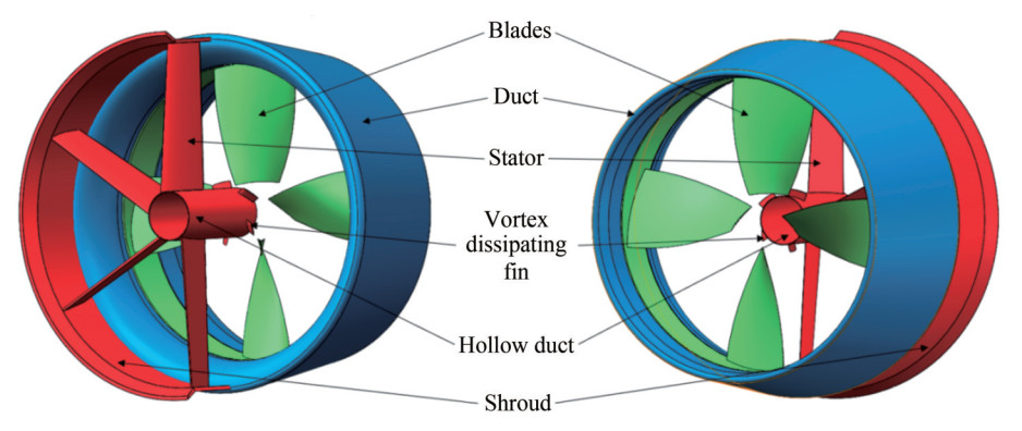 Figure 1 Annotations for shaftless RDT with a new type of appendage
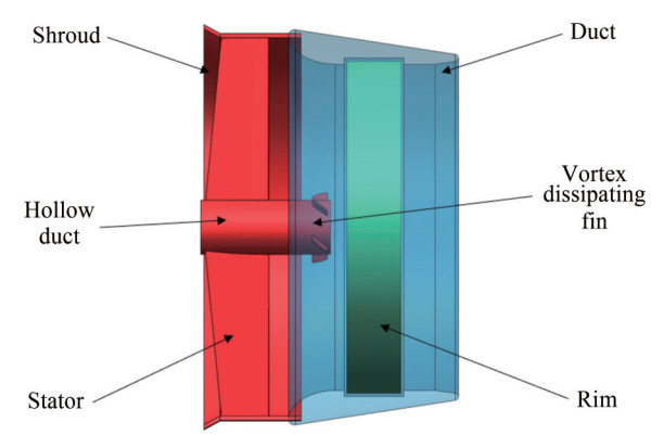 Figure 2 Perspective view of a shaftless RDT with a new type of appendage
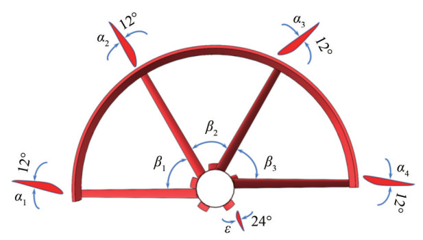 Figure 3 Schematic of attack angle and included angle of the new type of appendage
The development of the novel appendage, as introduced in this research, is tailored for an RDT. This thruster features a propeller blade with a diameter (D) of 240 mm, a pitch-to-diameter ratio (P/D) of 1.2, and a disk area ratio (AE/AD) of 0.5. For a comprehensive specification of the propeller characteristics, Table 2 is provided. The blade segment proximal to the rotational hub is termed the blade tip, whereas the distal segment is identified as the blade root. The blade's thickness profile exhibits central tapering, with thickness gradually increasing toward the periphery, showing a linear correlation with the radial distance from the axis of rotation. The stator elements are strategically configured to induce an axisymmetric tangential flow. This arrangement, combined with an elevation in the propulsion coefficient, leads to increased thrust from the rotor. This effectively offsets any drag introduced by the stator, thus achieving improved propulsion efficiency for the system.
Table 2 Main dimensions of the model RDTAsymmetrical prespin stator length (mm) Asymmetric prespin stator angle of attack (°) Number of asymmetric prespin stators (pcs) Center hollow catheter radius (mm) Axial length of the central hollow catheter (mm) Blade length of the leaf tip vortex offset device (mm) 120 12 4 20 96 6 Blade vortex offset device blade angle of
attack (°)Angle between asymmetrical prespin stators (°) Number of blades of the leaf tip vortex offset device (pcs) Semicircular duct tab thickness (mm) Center hollow catheter thickness
(mm)Blade section parameter airfoil
(two stator)24 60 5 1.5 1.2 NACA001 3 Numerical simulation method of hydrodynamics
3.1 Governing equation
The flow field surrounding the thrusters is analyzed using the RANS equations, which are fundamental for modeling incompressible Newtonian fluids. These equations encapsulate the essential dynamics of fluid behavior through the continuity and momentum equations:
$$ \frac{\partial u_i}{\partial x_i}=0 $$ (1) $$ \begin{aligned} & \rho\left(\frac{\partial u_i}{\partial t}+u_j \frac{\partial u_i}{\partial x_j}\right)=-\frac{\partial p}{\partial x_i}+\frac{\partial}{\partial x_j}\left[\mu\left(\frac{\partial u_i}{\partial x_j}+\frac{\partial u_j}{\partial x_i}\right)\right]+ \\ & \quad\quad\quad\quad \frac{\partial}{\partial x_j}\left(-\rho \overline{u_i^{\prime} u_j^{\prime}}\right) \end{aligned} $$ (2) where ρ is the fluid density, ui (i = 1, 2, 3, representing the component in the x, y, z direction, respectively) is the mean velocity component, t is the flow time, p is the pressure, μ is the dynamic viscosity, and $-\rho \overline{u_i^{\prime} u_j^{\prime}} $ is the Reynolds stress term.
In the context of incompressible Newtonian flows, the Reynolds stress is directly modeled through the Boussinesq hypothesis. This hypothesis suggests that the Reynolds stress is linearly related to the mean velocity gradients, facilitating a calculated estimation of stress within the fluid dynamics framework. Specifically, the Reynolds stress is calculated as
$$ -\rho \overline{u_i^{\prime} u_j^{\prime}}=\mu_t\left(\frac{\partial u_i}{\partial x_j}+\frac{\partial u_j}{\partial x_i}\right)-\frac{2}{3} \rho k \delta_{i j} $$ (3) where μt is the turbulent eddy viscosity, and δij is the Kronecker symbol.
Expanding upon the conventional k - ε turbulence model, Kinnas et al. (2009) introduced the realizable k - ε turbulence model. It incorporates subtle corrections related to curvature and rotational dynamics into the viscosity parameter of turbulence equations. These adjustments address diffusion rates, particularly focusing on the velocities of planar and circular jet diffusions. Additionally, the model includes a transport equation specifically designed to delineate turbulent kinetic energy, shedding light on the rate of turbulence dissipation. Compared with the conventional k - ε turbulence model, this refined methodology demonstrates superior computational accuracy, particularly adept at handling rotations, boundary layer separations, complex fluid dynamics within conduits, and flows encountering significant adverse pressure gradients.
The equations for the realizable k - ε turbulence model are defined as follows:
$$ \begin{aligned} & \frac{\partial(\rho k)}{\partial t}+\nabla \cdot(\rho k \boldsymbol{u})-\nabla \cdot\left[\left(\mu+\frac{\mu_{\mathrm{t}}}{\sigma_{\mathrm{k}}}\right) \nabla k\right]= \\ & \quad\quad P_{\mathrm{k}}+P_{\mathrm{b}}-Y_{\mathrm{M}}-\rho \varepsilon+S_{\mathrm{k}} \end{aligned} $$ (4) $$ \begin{aligned} & \frac{\partial(\rho \varepsilon)}{\partial t}+\nabla \cdot(\rho k \boldsymbol{u})-\nabla \cdot\left[\left(\mu+\frac{\mu_1}{\sigma_{\varepsilon}}\right) \nabla \varepsilon\right]= \\ & \quad\quad \rho C_1 S_{\varepsilon}-\rho C_2 \frac{\varepsilon^2}{k+\sqrt{v \varepsilon}}+C_{1 \varepsilon} \frac{\varepsilon}{k} C_{3 \varepsilon} P_{\mathrm{b}}+S_{\varepsilon} \end{aligned} $$ (5) In the above equation, $ C_1=\max \left[0-43, \frac{\eta}{\eta+5}\right]$, $ \eta=S \frac{k}{\varepsilon}$, $S=\sqrt{2 S: S} $, C1z = 1.44, C2 = 1.9, σi = 1.0, and σz = 1.2. Pk can be expressed as the generation of a mean velocity gradient in the kinetic energy generation term for turbulence. Pt generated by the kinetic energy of the turbulence is the resulting buoyancy force. S is expressed as a strain rate model.
3.2 Nondimensionalization of hydrodynamic characteristics
The study of RDTs involves computing hydrodynamic coefficients using a specific formula established by Gaggero (2020). This formula translates thrust and torque data derived from open-water tests into dimensionless terms. Key parameters include the advance coefficient J, rotor's rotational speed N, its diameter D, thrust produced by the propeller TP, thrust attributable to the duct TD, thrust generated by the novel appendage TA, and torque exerted by the rotor Q. The fundamental equation governing these relationships is formulated as follows:
Advance coefficient:
$$ J=\frac{V_{\mathrm{a}}}{N D} $$ (6) Thrust coefficient of rotor:
$$ K_{\mathrm{TP}}=\frac{T_{\mathrm{p}}}{\rho N^2 D^4} $$ (7) Thrust coefficient of duct:
$$ K_{\mathrm{TD}}=\frac{T_{\mathrm{D}}}{\rho N^2 D^4} $$ (8) Thrust coefficient of stator:
$$ K_{\mathrm{TA}}=\frac{T_{\mathrm{A}}}{\rho N^2 D^4} $$ (9) Total thrust coefficient:
$$ K_{\mathrm{TT}}=\frac{T_{\mathrm{p}}+T_{\mathrm{D}}+T_{\mathrm{A}}}{\rho N^2 D^4}=K_{\mathrm{TP}}+K_{\mathrm{TD}}+K_{\mathrm{TA}} $$ (10) Torque coefficient of rotor:
$$ K_{\mathrm{Q}}=\frac{Q}{\rho N^2 D^5} $$ (11) Open-water efficiency:
$$ \eta_0=\frac{J}{2 \mathtt{π}} \frac{K_{\mathrm{TT}}}{K_{\mathrm{Q}}} $$ (12) 4 Numerical computation model
4.1 Computational domain setup for RDTs
In the open-water computational analysis of the RDT, the domain comprises two cylindrical volumes: a larger stationary external cylinder and a smaller rotating internal one. As depicted in Figure 4, the external cylinder, representing the stationary domain, extends to a height of 18 times the propeller diameter (18D) with a base radius of four times the propeller diameter (4D). The internal cylinder, which encloses the rotor, is dimensioned precisely, although detailed specifications are not provided here. The thruster is positioned such that it is five propeller diameters (5D) from the velocity inlet and thirteen propeller diameters (13D) from the pressure outlet, following the configuration reported by Liu et al. (2017).
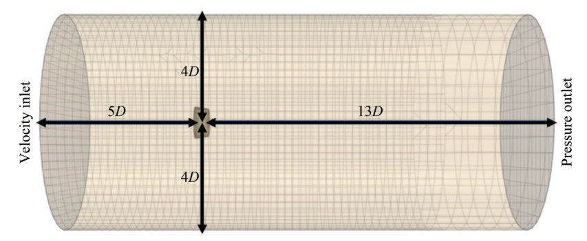 Figure 4 Meshed domain of RDT: Illustrating distances to boundaries with D = propeller diameter
The computational investigation conducted in this research utilizes the STAR-CCM+software, where the Boolean subtraction is executed in two distinct phases. First, the rotating domain containing the rotor, along with the rotor itself, undergoes Boolean subtraction, resulting in the delineation of the rotating domain. This step remains consistent even with the addition of the novel appendage. Subsequently, the inputs for the second phase include the extensive external stationary cylinder, the internal rotating cylinder, the duct, and the rotor, culminating in the definition of the stationary domain as the final output.
Achieving a high-quality mesh is crucial for accurate simulations, particularly maintaining consistent base mesh dimensions at the boundaries between rotating and stationary domains. This ensures a seamless mesh transition and enables accurate and stable data exchange. Mesh refinement primarily focuses on the rotor and duct surfaces, with additional refinement along the geometric model's periphery. Three distinct mesh configurations were tested to assess their impact on the results. Figure 5 illustrates the refinement of the three mesh sets for the RDT, both pre and post attachment installation. The study of grid sensitivity was conducted through mesh refinement, with a detailed validation of grid independence presented in Section 4.2. A designated refinement zone at the aft section of the RDT facilitates a detailed analysis of the axial and tangential velocity flow fields. The internal rotating cylinder domain reflects the rotor's dynamic motion. Utilizing the MRF methodology, as described by Song et al. (2015), the computational domain is segmented according to varying rotation rates, with each section assigned a distinct reference frame. This setup allows for the independent rotation or translation of segments, with fluid information exchanged through interfaces, emphasizing the importance of smooth transitions. The MRF technique, known for its steady-state approximation of actual conditions, is adopted in this study for its computational robustness, convergence efficiency, temporal expediency, and cost-effectiveness. Ensuring appropriate physical models and initial conditions is essential for CFD simulations. The turbulence model is set to the realizable k - ε model, with material properties defined for a liquid of constant density. Configuring the boundary conditions, the velocity inlet is established as the inflow face of the external stationary large cylindrical domain, with the inlet velocity specified in the boundary conditions. The outflow face of the external stationary cylinder serves as a pressure outlet. The wall between the stationary and rotating domains is treated as a symmetrical plane, whereas the walls of the rimless propeller are set to no-slip conditions.
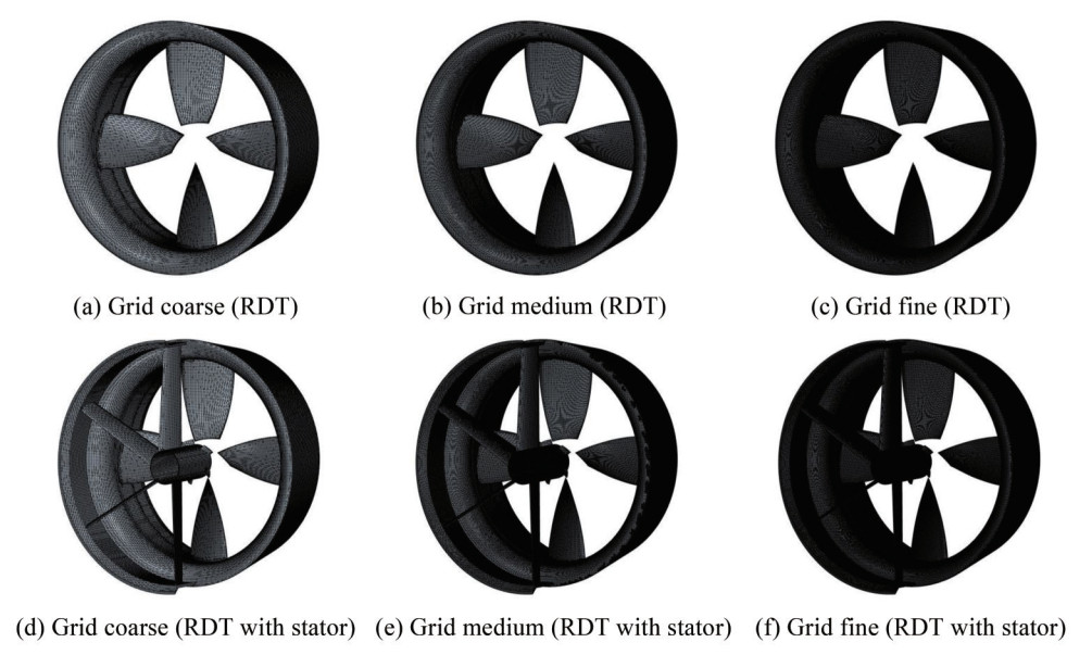 Figure 5 Surface grid division of two types of RDTs
4.2 Independent verification of computational grid model
The determination of base mesh dimensions and the selection of turbulence model parameters significantly impact the accuracy of CFD simulations. Acknowledging the importance of mesh granularity, this study adheres to the guidelines established by the International Towing Tank Conference (ITTC) (ITTC, 2011). Through a systematic calibration of the mesh size variation rate, three distinct mesh configurations—A1, A2, and A3—have been developed, with foundational dimensions of 0.198, 0.140, and 0.099, respectively. Corresponding mesh counts for these configurations are 1.69 million, 2.4 million, and 3.16 million, as depicted in Figure 6. Comparative analyses delineating variations in thrust and torque coefficients are methodically presented in Tables 3 and 4.
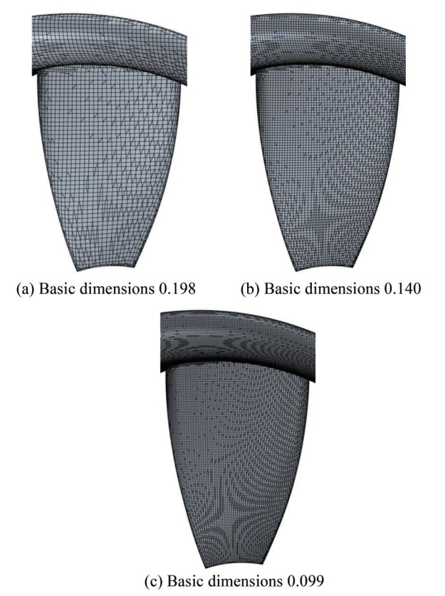 Figure 6 Comparison of grids with different basic sizesTable 3 Comparison of differences in thrust coefficient
J KTA1 KTA2 δ (KTA1, KTA2) (%) KTA3 δ (KTA2, KTA3) (%) 0.1 0.717 0.724 0.976 0.727 0.363 0.2 0.648 0.657 1.333 0.660 0.402 0.3 0.585 0.594 1.614 0.601 1.213 0.4 0.521 0.534 2.426 0.541 1.362 0.5 0.460 0.478 3.922 0.486 1.616 0.6 0.406 0.423 4.139 0.431 1.882 Table 4 Comparison of differences in torque coefficientJ 10×KQA1 10×KQA2 δ (KQA1, KQA2)(%) 10×KQA3 δ (KQA2, KQA3)(%) 0.1 0.893 0.909 1.731 0.911 0.216 0.2 0.887 0.904 1.929 0.908 0.409 0.3 0.872 0.896 2.788 0.906 1.124 0.4 0.860 0.884 2.819 0.897 1.447 0.5 0.838 0.866 3.371 0.882 1.884 0.6 0.814 0.842 3.423 0.862 2.319 4.3 Reliability verification of calculation method
Within the scope of this investigation, the rotor's rotational velocity was set at 120 rad/s. It has been observed that an increase in the advance coefficient correlates with a greater divergence in thrust and torque coefficients, particularly when varying mesh dimensions are taken into account. These trends suggest that higher advance coefficients may exacerbate the complexity of flow interactions at the rotor's boundary and the duct, potentially compromising the accuracy of open-water simulations for the RDT. Consequently, for future research assessing the energy-saving potential of the novel appendage, the advance coefficient should be limited to a prudent range between 0.1 and 0.6 to ensure the reliability of the energy-saving assessments.
Examination of thrust and torque coefficient fluctuations, as depicted in Figure 7, suggests that reducing the foundational mesh size below 0.14 and increasing the mesh count beyond 2.4 million stabilizes coefficient variations, eventually reaching a plateau. Notably, Figure 8 demonstrates that the variance in hydrodynamic coefficients for both propellers across all examined models remains within a 3% margin. Thus, further mesh refinement does not necessarily correlate with substantial gains in computational precision.
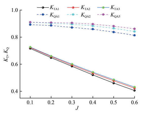 Figure 7 Hydrodynamic characteristic curves of RDT under direct sailing for various advance coefficients
However, a more intricate mesh increases computational demands. Given the near equivalence of outcomes between the medium and finer meshes, the medium-density mesh has been chosen for subsequent numerical analyses. In this study, the open-water numerical curves of the rimless RDT (depicted in Figure 8), with a particular focus on propulsion efficiency, were compared against the computational results of the same model published by other scholars (Cai et al. 2015). This comparison was based on a medium-density mesh. The efficiency curves align well at higher advance coefficients, but slight fluctuations are evident at lower coefficients. This correlation supports the validity of the simulation calculations conducted in this section.
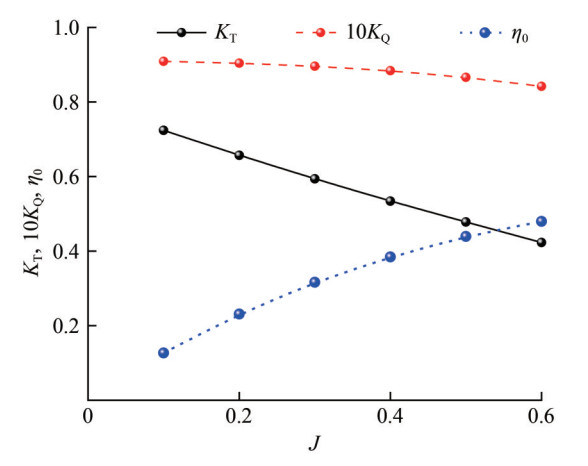 Figure 8 Shaftless RDT open-water numerical curve
Figure 9 illustrates that, with the advance coefficient held constant at 0.4, Y+ values on both the leading and trailing surfaces of the rimless propeller fluctuate between 2.173 6 and 72.891. Particularly noteworthy is the observation that the propeller's leading edge, trailing edge, and blade root display reduced Y+ values, a phenomenon primarily attributed to the targeted mesh refinement in regions with intricate surface geometries. The realizable k - ε turbulence model employed requires Y+ values to remain below a threshold of 200. The meshing approach adopted ensures compliance with the Y+ criteria stipulated by the turbulence model.
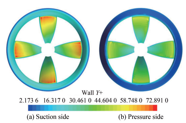 Figure 9 Y+ distribution of the RDT (medium grid)
5 Calculation results and analysis
In this study, a comparative assessment was conducted to determine the propulsion efficiency gains achieved by integrating the innovative appendage across an advance coefficient spectrum of J = 0.1–0.6. As demonstrated in Table 5 and Figure 10, the efficiency enhancement reached its peak at 2.905% at an advance coefficient of J = 0.5. Conversely, at the lower end of the spectrum, specifically at J = 0.1, the efficiency increment was marginal, with a noted decrement of − 0.931%. This outcome is hypothesized to result from the pronounced suction effect exerted by the rotor at lower advance coefficients, which channels a substantial flow toward the rotor blade plane, thereby reducing the pre-swirl efficacy of the appendage. Such conditions diminish the lift-inducing capability of the airfoil-shaped stator and accentuate the drag incurred by the appendage. With an increase in the advance coefficient, the rotor's suction impact diminishes, allowing the appendage to facilitate a more equitable flow distribution and consequently capitalize on the pre-swirl benefits.
Table 5 Comparison before and after installing the novel appendageJ KT 10KQ η0 (%) Improve (%) Before After Before After Before After 0.1 0.724 0.722 0.909 0.915 12.676 12.558 −0.931 0.2 0.657 0.667 0.904 0.910 23.134 23.331 0.852 0.3 0.594 0.610 0.896 0.902 31.653 32.290 2.012 0.4 0.534 0.553 0.884 0.891 38.456 39.512 2.746 0.5 0.478 0.497 0.866 0.875 43.924 45.200 2.905 0.6 0.423 0.441 0.842 0.855 47.973 49.254 2.670 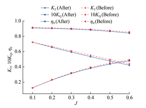 Figure 10 Comparison diagram before and after installing the new type of appendage
Figure 10 presents the propulsion performance curves for two RDTs following the mitigation of turbulence grid anomalies and stochastic velocity fluctuations, utilizing three distinct grid configurations. With the integration of the appendage, the water flow through the rotor disk area demonstrates heightened interaction with the rotor blades, resulting in a notable increase in both the thrust and torque coefficients of the system. The rotational flow induced by the pre-swirl, a consequence of the novel appendage's design, contributes to a reduction in energy dissipation within the rotor's wake. Optimal energy conservation efficiency, achieved at an advance coefficient of J = 0.5, is quantified at 2.905%, with subsequent efficiencies of 2.746% at J = 0.4 and 2.670% at J = 0.6, as outlined in Table 5. At lower advance coefficients, the rotor's suction effect partially counters the energy-saving function of the appendage. Furthermore, the stator's pitch and yaw angles, in conjunction with the wakes from upstream control surfaces, induce an asymmetrical inflow, which, despite minor reductions in propulsion performance, results in a net propulsion control benefit. These findings underscore the innovative stator appendage's capacity to optimize blade loading dynamics and force distribution across the rotor's operational regime.
The rotor's performance is notably affected by disturbances in the inflow, primarily stemming from the wake of the preceding stator. However, strategic modifications to the stator's configuration can greatly alleviate the resulting instabilities in the rotor. By extending the length of the stator blades beyond the radius of the rotor blades, the interaction with the stator tip vortices is effectively reduced. Additionally, limiting the range of the stator's pitch distribution can significantly minimize instabilities in the rotor inflow. It is crucial to acknowledge that when the stator is refined for maneuverability and control, as proposed here, any slight reduction in propulsion efficacy is temporary. As advance coefficients increase, the propulsive efficiency of a stator-equipped propulsor becomes increasingly pronounced.
To meticulously analyze the detrimental impacts of tip vortex accumulation on the propulsion efficiency of the RDT, the computational grid was refined in the vicinity of the duct's trailing edge and the wake region downstream of the propeller, building on previous grid stratification efforts. Turbulence dynamics were modeled using the large eddy simulation approach, known for its ability to capture the nuances of tip vortex behavior. As depicted in Figure 11(a), the shedding of vortices from the duct's trailing edge is evident, with the outermost layer of the vortex spiraling rearward—a result of the interaction between the rotor's root and the duct. In Figure 11(b), the central region of the RDT lacks flow guidance, attributed to the absence of conventional flow elements such as a propeller hub. Figure 11(c) highlights that the rotor tips serve as the origin of a pronounced rotational tip vortex. This vortex, combined with the local wake flow, fosters a confluence and intensification of vortices, resulting in the aggregation effect. This aggregation leads to an irregular force distribution on the rotor blades, consequently diminishing the propulsive efficiency of the RDT.
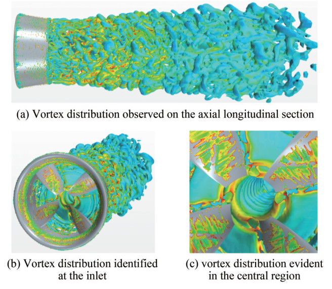 Figure 11 Distribution of tip vortices
The flow dynamics within the gap bounded by the innovative appendage and the rotor are elucidated through a radial cross-section, as shown in Figure 12. In regions without the pre-swirl stator, Stator 1 propels, catalyzing tangential acceleration within the unoccupied sector. Conversely, situated proximally, Stator 4 induces suction, eliciting a pronounced pre-swirl influence on the flow. Future investigations can benefit from calibrating the attack angles of Stators 1 and 4 to optimize the pre-swirl effect. Within the ambit delineated by the stator assembly, the pre-swirl flow exhibits a centripetal orientation, resonating with the suction effect of the adjacent rotor. The strategic configuration of stator angles, coupled with their inherent attack angles, orchestrates a pre-swirl in the inflow, equalizing flow distribution before engagement with the propeller disc. This synergy enhances the propulsive efficacy of the rimless thruster. The refined analysis of the flow field proximal to the vortex-dissipating fin within the central conduit is depicted in Figure 12. The fin's design, notable for its pronounced attack angle and compact form, considerably enhances both circumferential and axial flow velocities within the delimited annular space. This design effectively orchestrates and expedites flow, achieving a maximum velocity of 2.855 7 m/s in this region. Notably, this configuration induces clockwise flow rotation, mitigating natural rotational movement at the rotor blade tip. This feature plays a pivotal role in reducing the adverse effects of tip vortex concentration on the propulsion efficiency of the RDT.
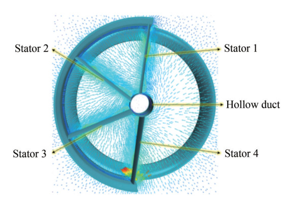 Figure 12 Velocity vector diagram of the new type of appendage
The study delineates that within the rotor disk's upper hemisphere, the novel energy-saving stator configuration imparts a positive tangential velocity. This velocity, combined with the rotor's counterclockwise motion, leads to a lagging blade condition. Under these circumstances, the local angle of attack on the rotor blade decreases, resulting in reduced blade load, thrust, and axial momentum transferred to the wake. In contrast, the rotor disk's lower hemisphere experiences an advancing blade scenario, where the local angle of attack on the rotor blade increases because of the tangential flow opposing the rotor's rotation. This increase enhances blade load, thrust, and axial momentum imparted into the system's trailing wake. Concurrently, as depicted in Figure 13, whereas the circulatory flow is maintained, its magnitude is reduced by the axial flow's modulation through the rotor disk. This effect is conspicuously manifested in the streamwise vorticity distribution, with a notable reduction in tip vortex intensity following the rotor's integration. These observations imply that the rotor adeptly reallocates energy from the rotational flow, transitioning from the stator's circulatory pattern to an axial thrust.
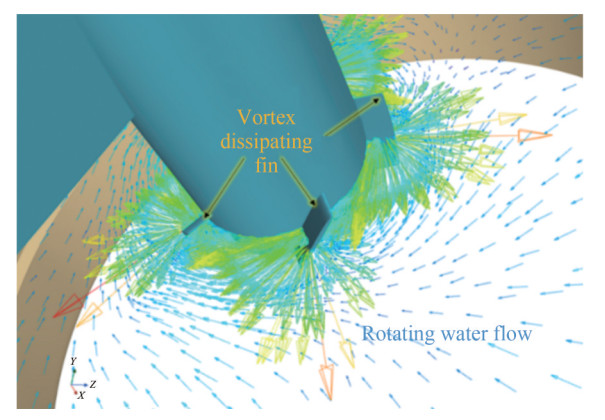 Figure 13 Velocity vector diagram of blade tip vortex inefficient device
In the analysis presented in Figure 14, the axial velocity profiles are compared before and after integrating the novel appendage. Post-integration, a peak axial velocity of 3.114 8 m/s is recorded, a significant increase from the baseline of 2.958 3 m/s, reflecting a 5.29% enhancement. As highlighted by Go et al. (2017), a pre-positioned stator exerts a rectifying and pre-swirling effect on the inflow to the propeller. This underscores the efficacy of the appendage in refining and accelerating the inflow, thereby providing an augmented initial velocity to the flow field as it approaches the rotor disk. Further examination of the velocity distribution nuances indicates that before the appendage's integration, a pronounced diffusion tendency is discernible in the water flow just aft of the rotor's hub, typically associated with rotational energy dissipation. Conversely, with the appendage's implementation, the wake directly aft of the disk's core exhibits a notably uniform and streamlined axial profile, reducing radial dispersion. This demonstrates the success of the tip vortex counteracting mechanism, which, through the integration of five vortex fins, markedly reduces tip vortex convergence, thus enhancing the propulsive efficiency of the RDT. The asymmetric design of the energy-efficient stator appendage results in a non-axisymmetric flow distribution downstream of the stator. The stator's configuration inherently generates a significant lateral force, which increases linearly with the distance from the rotor. Positioned downstream of the stator, the rotor experiences a diminished lateral force from the stator, albeit with a minor accompanying normal force and associated pitching moment.
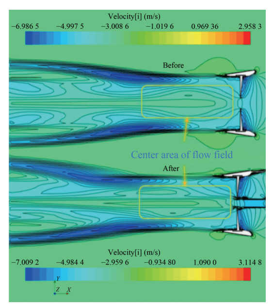 Figure 14 Comparison of the center area of the flow field before and after installation
Considering the significant relationship between pressure distribution and flow dynamics, the pressure contours at an advance coefficient of J = 0.4, depicted in Figure 15(a), show that the semicircular duct exhibits notably higher pressure values compared with the region influenced by the pre-rotation stator. Consequently, the thrust generated by the stator surpasses its inherent drag, thereby enhancing the overall thrust coefficient. In contrast, the pressure contours at J = 0.6, illustrated in Figure 15(b), reveal a different dynamic. Here, the pressure exerted by the stator exceeds that induced by the duct, resulting in a situation where the stator's net thrust is counteracted by its drag. This underscores the stator's ability to boost the propulsive efficiency of the RDT under specific operational parameters.
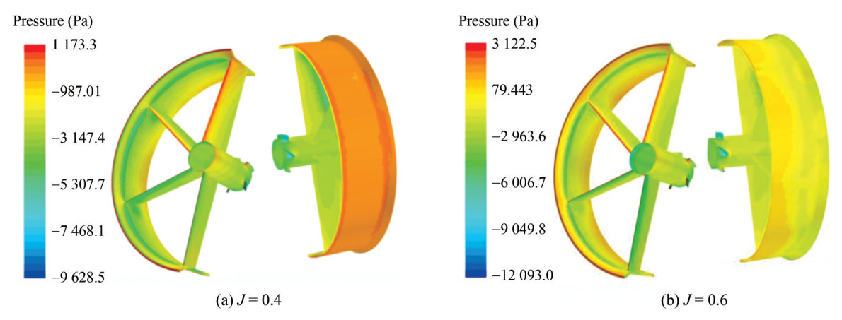 Figure 15 Pressure clouds of the new type of appendage
In the context of examining the suction side pressure response of the RDT's rotor, the inclusion of a pre-positioned stator has demonstrated significant enhancement. Owing to the unique drive form of the RDT, it exhibits superior cavitation characteristics, as noted by Yakovlev et al. (2011). Specifically, compared with the RDT lacking a pre-positioned stator, the one equipped with the stator shows improved cavitation performance in the pressure distribution on the rotor's suction side. As depicted in Figure 16, at Va = 1.87 m/s, the pressure distribution contours on the front (inflow-facing) and back (outflow-facing) sides of the rotor with and without the stator exhibit notable differences. With the addition of the novel appendage stator, the low-pressure area on the rotor's inflow side significantly diminishes, particularly near the blade edges, indicating a considerable pressure increase and a tendency for the low-pressure area at the blade tips to contract toward the root. This modification in pressure distribution assists in reducing cavitation occurrence, as highlighted by Cai et al. (2015), who noted that cavitation typically occurs in low-pressure areas. Concurrently, the low-pressure area on the rotor's outflow side decreases, and the expansion of the high-pressure zone results in an increased pressure differential across the blade surface, thereby generating stronger thrust. This alteration in pressure distribution not only mitigates the risk of cavitation but also effectively enhances the thrust coefficient of the RDT, indicating a notable improvement in cavitation performance with the incorporation of the pre-positioned stator.
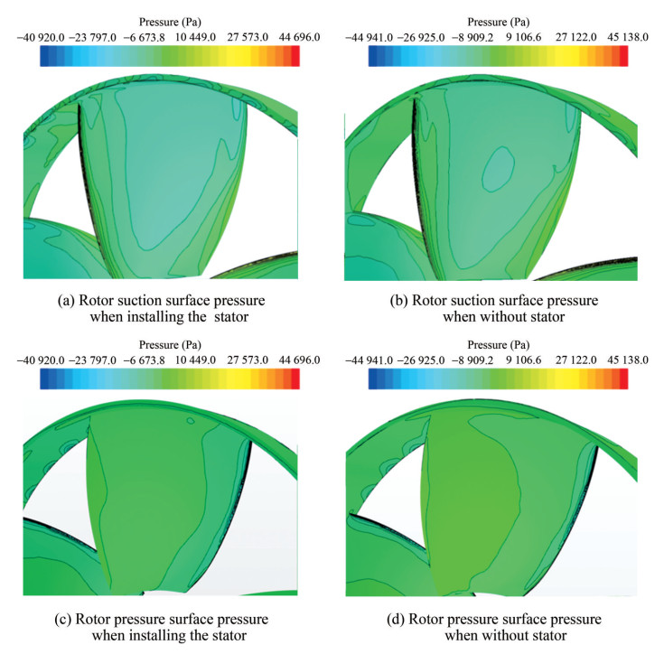 Figure 16 Comparison of rotor surface pressure field before and after stator installation
Examination of Figure 17, depicting the peak velocity near the innovative auxiliary stator, reveals a notable decrease in flow velocity at an advance coefficient of J = 0.2 compared with J = 0.1. This velocity trend, rising from J = 0.2 to J = 0.6, shows a consistent increase, corresponding to the observed enhancement in propulsion efficiency following stator integration. Interestingly, despite an initial decrease in propulsion efficiency at J = 0.1, a uniform improvement is evident from J = 0.2 to J = 0.6. As the advance coefficient exceeds J = 0.2, the energy-conservation role of the RDT, reinforced by the inclusion of the auxiliary stator, becomes more prominent. This highlights the rotor's suction effect, which compromises the auxiliary's energysaving efficiency at lower advance coefficients. With the incremental increase in J, the color representing peak velocity around the auxiliary intensifies at the core, promoting a balanced velocity profile in the rotor's aft region. From an energy balance perspective, this phenomenon helps reduce hydrodynamic energy loss over the rotor's surface, thereby decreasing torque demand and enhancing propulsive efficiency. A comparison at J = 0.5 and J = 0.6 reveals an excessive concentration of the auxiliary's peak velocity during the transition, resulting in an uneven velocity profile and subsequent reduction in propulsion efficiency at J = 0.6 compared with J = 0.5.
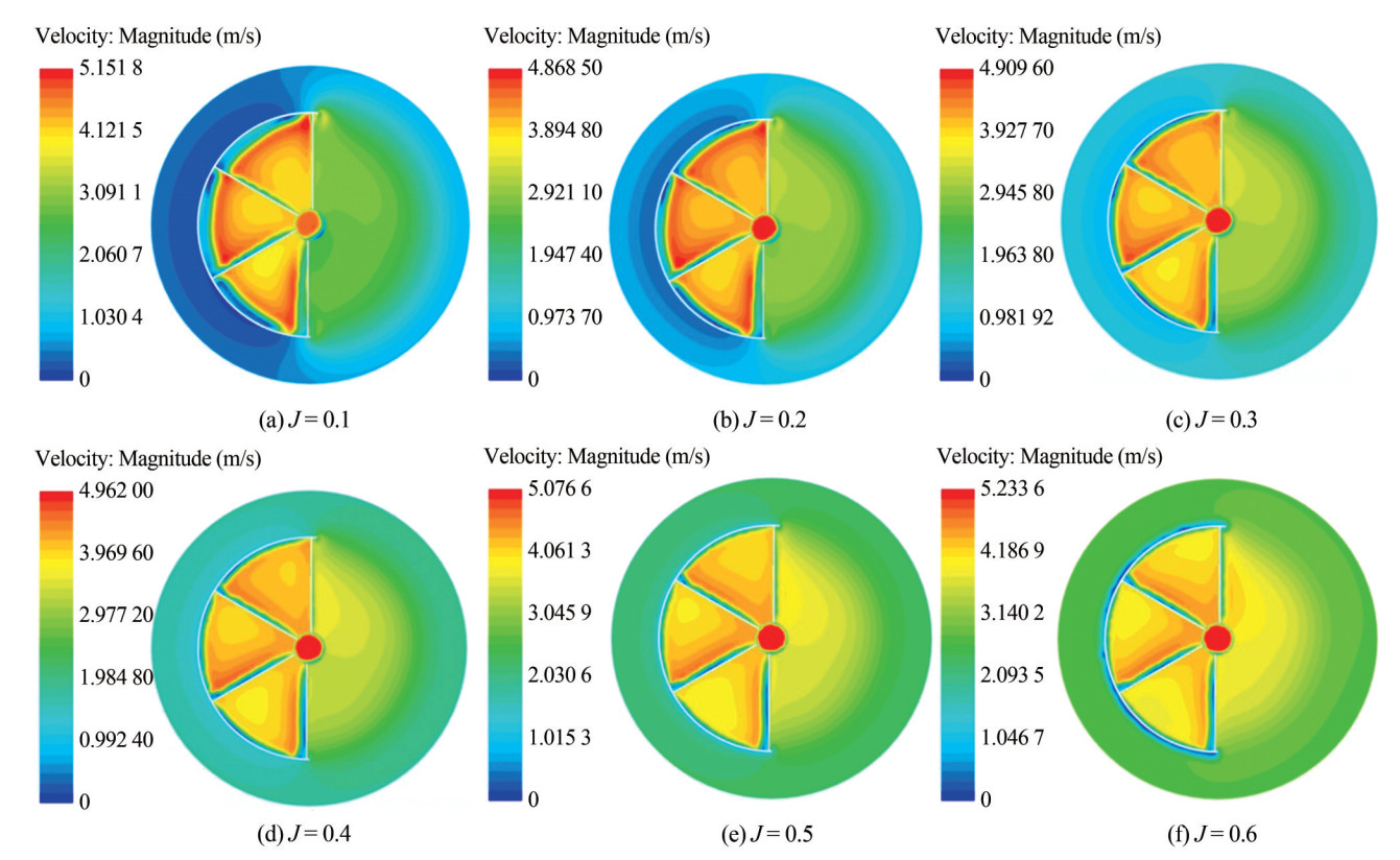 Figure 17 Comparison of the maximum velocity of the new type of appendage
Figure 17 examines the velocity dynamics within the wake at a cross-section perpendicular to the rotor's axial path. A carefully chosen location, positioned away from the rotor plane along its axis, allows for the investigation of axial flow dynamics across a range of advance coefficients.
The blade velocity near a stator significantly surpasses that in stator-absent conditions. Moreover, the overall average velocity in scenarios with a stator consistently exceeds that without, indicating that rotor blades are more effective at directing energy to accelerate water through the stator. The velocity distribution at this sectional plane is further elaborated in Figure 17, where the impact of the stator wake at this point appears diminished. Owing to the nuanced interference of the stator wake, areas displaying both linear and curvilinear velocity reduction patterns are observable. Concurrently, the velocity increase correlates with the rise in advance coefficient. Axial representations for stator-equipped and stator-free configurations are presented anterior to the rotor at x = 0.2D, corresponding to coefficients Va = 0.64 m/s and 1.87 m/s, respectively. The instrumental influence of the stator in modulating the inflow toward the rotor, particularly its lateral velocity component, is thus underscored. By orchestrating the flow counter to the rotor's rotation, the stator effectively mitigates losses incurred by the rotor's slipstream, thereby optimizing the efficacy of the propulsion system.
6 Conclusions
In the current study, an initial numerical assessment was conducted to investigate the hydrodynamic characteristics of RDTs enhanced by an innovative energy-conserving appendage across a range of advance coefficients. The realizable k - ε turbulence model was employed as the computational tool to analyze the hydrodynamic phenomena of two distinct rimless thruster configurations. The MRF methodology was utilized to handle the static and dynamic mesh arrangements within the computational framework. Insights derived from RDT simulations before and after integrating the novel energy-saving appendage led to the following conclusions:
The design of the new appendage enhances the pressure difference between the blade face and its back, thereby increasing the thrust of the rimless wheel propulsor. A substantial reduction in the low-pressure area is observed on the rotor's inflow surface, particularly at the blade edges, indicating a notable pressure increase and a tendency for the low-pressure zone to contract toward the blade root. On the rotor's back, the low-pressure area decreases while the high-pressure zone expands, resulting in a noticeable increase in the pressure differential across the blade surfaces. This change in pressure distribution helps reduce the occurrence of cavitation. Compared with the configuration before the stator installation, the integration of the new energy-saving appendage leads to a more contracted wake trend behind the rotor disk, resulting in a more uniform wake field distribution. Additionally, the mechanism for dissipating vortices at the blade tips reduces the concentration of tip vortices, resulting in a more uniform force distribution on the rotor.
This investigation presents a design methodology tailored for engineers specializing in the construction of rotorstator configurations for surface and underwater vessels. The study unveils a significant benefit: the strategic integration of a stator substantially reduces the adverse effects on rotor torque, a crucial factor in enhancing the directional stability of high-speed submersibles. Future research will focus on refining the spatial interaction between the novel energy-saving appendage and the rotor to deepen the understanding of stator operational dynamics. However, a notable limitation must be acknowledged: the current lack of suitable experimental setup confines this inquiry to computational simulations. These simulations evaluate the hydrodynamic efficacy of an RDT enhanced with the innovative appendage. The next phase of research is dedicated to establishing an experimental framework to validate the computational simulation approaches employed.
Competing interest The authors have no competing interests to declare that are relevant to the content of this article. -
Figure 1 Annotations for shaftless RDT with a new type of appendage
Figure 2 Perspective view of a shaftless RDT with a new type of appendage
Figure 3 Schematic of attack angle and included angle of the new type of appendage
Figure 4 Meshed domain of RDT: Illustrating distances to boundaries with D = propeller diameter
Figure 5 Surface grid division of two types of RDTs
Figure 6 Comparison of grids with different basic sizes
Figure 7 Hydrodynamic characteristic curves of RDT under direct sailing for various advance coefficients
Figure 8 Shaftless RDT open-water numerical curve
Figure 9 Y+ distribution of the RDT (medium grid)
Figure 10 Comparison diagram before and after installing the new type of appendage
Figure 11 Distribution of tip vortices
Figure 12 Velocity vector diagram of the new type of appendage
Figure 13 Velocity vector diagram of blade tip vortex inefficient device
Figure 14 Comparison of the center area of the flow field before and after installation
Figure 15 Pressure clouds of the new type of appendage
Figure 16 Comparison of rotor surface pressure field before and after stator installation
Figure 17 Comparison of the maximum velocity of the new type of appendage
Table 1 Literature review of the ESD
Authors ESD Result Lee et al. (1992) Daewoo pre-swirl system Propulsion efficiency is enhanced Mewis and Peters (1986) SVA fin system Rotational losses are reduced Streckwall and Xing-Kaeding (2017) Pre-swirl stator (PSS) Reduction in power among tankers is more substantial than that among container ships Nadery and Ghassemi (2020) PSS A 2.3% increase in delivered power is realized Mewis (2008; 2009) Power spectral density (PSD) An average energy saving of 6.3% is noted Dang et al. (2011) PSD, PSS, and PBCF PSD can reduce the total kinetic energy level, and the vortex system shed by fins can induce additional rotational loss Kim et al. (2015) PSS and PSD Propulsive efficiency is improved Coache and Meis Fernández (2017) PSS, WED, and rudder bulb PSS has superior effects on propulsion efficiency compared with two other ESDs Nowruzi and Najafi (2019) Three types of PSD Mewis PSD has the highest value of thrust and torque at high advance ratios Table 2 Main dimensions of the model RDT
Asymmetrical prespin stator length (mm) Asymmetric prespin stator angle of attack (°) Number of asymmetric prespin stators (pcs) Center hollow catheter radius (mm) Axial length of the central hollow catheter (mm) Blade length of the leaf tip vortex offset device (mm) 120 12 4 20 96 6 Blade vortex offset device blade angle of
attack (°)Angle between asymmetrical prespin stators (°) Number of blades of the leaf tip vortex offset device (pcs) Semicircular duct tab thickness (mm) Center hollow catheter thickness
(mm)Blade section parameter airfoil
(two stator)24 60 5 1.5 1.2 NACA001 Table 3 Comparison of differences in thrust coefficient
J KTA1 KTA2 δ (KTA1, KTA2) (%) KTA3 δ (KTA2, KTA3) (%) 0.1 0.717 0.724 0.976 0.727 0.363 0.2 0.648 0.657 1.333 0.660 0.402 0.3 0.585 0.594 1.614 0.601 1.213 0.4 0.521 0.534 2.426 0.541 1.362 0.5 0.460 0.478 3.922 0.486 1.616 0.6 0.406 0.423 4.139 0.431 1.882 Table 4 Comparison of differences in torque coefficient
J 10×KQA1 10×KQA2 δ (KQA1, KQA2)(%) 10×KQA3 δ (KQA2, KQA3)(%) 0.1 0.893 0.909 1.731 0.911 0.216 0.2 0.887 0.904 1.929 0.908 0.409 0.3 0.872 0.896 2.788 0.906 1.124 0.4 0.860 0.884 2.819 0.897 1.447 0.5 0.838 0.866 3.371 0.882 1.884 0.6 0.814 0.842 3.423 0.862 2.319 Table 5 Comparison before and after installing the novel appendage
J KT 10KQ η0 (%) Improve (%) Before After Before After Before After 0.1 0.724 0.722 0.909 0.915 12.676 12.558 −0.931 0.2 0.657 0.667 0.904 0.910 23.134 23.331 0.852 0.3 0.594 0.610 0.896 0.902 31.653 32.290 2.012 0.4 0.534 0.553 0.884 0.891 38.456 39.512 2.746 0.5 0.478 0.497 0.866 0.875 43.924 45.200 2.905 0.6 0.423 0.441 0.842 0.855 47.973 49.254 2.670 -
Bhattacharyya A, Krasilnikov V, Steen S (2016) A CFD-based scaling approach for ducted propellers. Ocean Engineering 123: 116–130. https://doi.org/10.1016/j.oceaneng.2016.06.011 Cai M, Yang C, Wu S, Zhu Y, Xie Y (2015) Hydrodynamic analysis of a rim-driven thruster based on RANS method. OCEANS 2015-MTS/IEEE Washington. Piscataway: IEEE 1–5. https://doi.org/10.23919/OCEANS.2015.7404398 Cao QM, Hong FW, Tang DH, Hu FL, Lu LZ (2012) Prediction of loading distribution and hydrodynamic measurements for propeller blades in a rim driven thruster. Journal of Hydrodynamics, Ser. B 24: 50–57. https://doi.org/10.1016/S1001-6058(11)60218-7 Çelik F, Güner M (2007) Energy saving device of stator for marine propellers. Ocean Engineering 34(5–6): 850–855. https://doi.org/10.1016/j.oceaneng.2006.03.016 Coache S, Meis Fernandez M (2017) ESD design for a validation bulk carrier. International Shipbuilding Progress 63(3–4): 211–226. https://doi.org/10.3233/ISP-170132 Dang J, Dong G, Chen H (2011) An exploratory study on the working principles of energy saving devices (ESDs). Symposium on Green Ship Technology (Greenship'2011). Wuxi Dubas AJ, Bressloff NW, Sharkh SM (2015) Numerical modelling of rotor-stator interaction in rim driven thrusters. Ocean Engineering 106: 281–288. https://doi.org/10.1016/j.oceaneng.2015.07.012 Fang G, Qian Z, Jiang J (2016) Research on sheet cavitation numerical predicted and estimation of tip vortex cavitation inception of ducted propeller with preswirl stator. Ship Sci Technol 38: 26–29 Gaggero S (2020) Numerical design of a RIM-driven thruster using a RANS-based optimization approach. Applied Ocean Research 94: 101941. https://doi.org/10.1016/j.apor.2019.101941 Go JS, Yoon HS, Jung JH (2017) Effects of a duct before a propeller on propulsion performance. Ocean Engineering 136: 54–66. https://doi.org/10.1016/j.oceaneng.2017.03.012 ITTC (2011) Practical guidelines for ship CFD applications. ITTC–recommended procedures and guidelines. In: International Towing Tank Conference 26th ITTC specialist committee on CFD in marine hydrodynamics 1–18 Kim JH, Choi JE, Choi BJ, Chung SH, Seo HW (2015) Development of energy-saving devices for a full slow-speed ship through improving propulsion performance. International Journal of Naval Architecture and Ocean Engineering 7(2): 390–398. https://doi.org/10.1515/ijnaoe-2015-0027 Kinnas S, Chang S-H, He L, Johannessen JT (2009) Performance prediction of a cavitating rim driven tunnel thruster. First International Symposium on Marine Propulsors. Norway 28(1): 72–82 Koushan K, Krasilnikov V, Nataletti M, Sileo L, Spence S (2020) Experimental and numerical study of pre-swirl stators PSS. Journal of Marine Science and Engineering 8(1): 47. https://doi.org/10.3390/jmse8010047 Lee JT, Kim MC, Suh JC, Kim SH, Choi JK (1992) Development of a preswirl Statorpropeller system for improvement of propulsion efficiency: A symmetric stator propulsion system. Journal of the Society of Naval Architects of Korea 29(4): 132–145 Liu B, Yan X, Ouyang W, Lan J, Liang X (2017) Research on regular pattern of gap flow in shaftless rim-driven thruster. 2017 4th International Conference on Transportation Information and Safety (ICTIS). 2017. 134–138. https://doi.org/10.1109/ICTIS.2017.8047756 Mewis F, Peters H (1986) Power savings through a novel fin system. In: SMSSH Conference. Varna, Bulgaria 9 Mewis F (2009) A novel power-saving device for full-form vessels. Proceedings of the First International Symposium on Marine Propulsors (SMP'09), Trondheim. Mewis F (2008) Development of a novel power-saving device for full-form vessels. Hansa: International Maritime Journal 11 Nadery A, Ghassemi H (2020) Hydrodynamic performance of the ship propeller under oscillating flow with and without stator. Am J Civ Eng Architect. 8(2): 56–61. https://doi.org/10.12691/ajcea-8-2-5 Nowruzi H, Najafi A (2019) An experimental and CFD study on the effects of different pre-swirl ducts on propulsion performance of series 60 ship. Ocean Engineering 173: 491–509. https://doi.org/10.1016/j.oceaneng.2019.01.007 Peng Y, Wang Y, Liu C, Yi W (2019) Comparative analysis of the hydrodynamic performance of front-stator and rear-stator pumpjets. Journal of Harbin Engineering University 40(1): 132–140. https://doi.org/10.11990/jheu.201707018 Shin YJ, Kim MC, Lee WJ, Lee KW, Lee JH (2015) Numerical and experimental investigation of performance of the asymmetric pre-swirl stator for container ship. Fourth International Symposium on Marine Propulsors Smp'15. Austin, TX, 305–310 Song BW, Wang YJ, Tian WL (2015) Open water performance comparison between hub-type and hubless rim driven thrusters based on CFD method. Ocean Engineering 103: 55–63. https://doi.org/10.1016/j.oceaneng.2015.04.074 Streckwall H, Xing-Kaeding Y (2017) On the working principle of pre-swirl stators and on their application benefit and design targets. International Shipbuilding Progress 63(3–4): 87–107 https://doi.org/10.3233/ISP-170124 Tan WZ, Yan XP, Liu ZL (2015) Technology development and prospect of shaft-lessrim driven propulsion system. Journal of Wuhan University Technology 39: 601–605 Van SH, Kim MC, Lee JT (1993) Some remarks on the powering performance prediction method for a ship equipped with a preswirl stator–propeller f system. Proceedings of the ITTC 2 Vărăticeanu BD, Minciunescu P, Nicolescu C, Matei SS, Neacşu MG (2017) Design and validation of a 2.5-kW electric naval propulsion system with rim driven propeller. 2017 Electric Vehicles International Conference (EV). Piscataway: IEEE 1–5. https://doi.org/10.1109/EV.2017.8242096 Vladimir N, Bakica A, Malenica S, Im H, Senjanovic I, Cho DS (2021) Numerical method for the vibration analysis of pre-swirl stator. Ships and Offshore Structures 16 (sup1): 256–265. https://doi.org/10.1080/17445302.2021.1907072 Voermas AAM (2017) Development of the Wärtsilä EnergoFlow: An innovative energy saving device. Proceedings of the 5th International Symposium on Marine Propulsors smp'17: Launceston, Finland 12–15 Witte M, Hieke M, Wurm F-H (2019) Identification of coherent flow structures and experimental analysis of the hydroacoustic emission of a hubless propeller. Ocean Engineering 188: 106248 https://doi.org/10.1016/j.oceaneng.2019.106248 Yang S, Hu P, Jin S, Wei Y, Lan R, Zhuang S, Zhu H, Cheng A, Chen J, Wang D, Liu D (2016) Design of novel shaftless pump-jet propulsor for multi-purpose long range and high speed autonomous underwater vehicle. IEEE Transactions on Magnetics 52: 1–4 Yakovlev A, Sokolov MA, Marinich NV (2011) Numerical design and experimental verification of a rim-driven thruster. Proceedings of Second International Symposium on Marine Propulsors. Hamburg 396–403 Zhang YY, Lai MY, Ni YG, Liang F (2021) CFD study of hull wakes in oblique flow at model and full scales. Applied Ocean Research 112(1): 355–367. DOI: 10.1016/j.apor.2021.102689 Zhang AM, Liu SM, Cui P, Li S, Liu YL (2023) A unified theory for bubble dynamics. Physics of Fluids. Physics of Fluids 35: 033323. https://doi.org/10.1063/5.0145415
