
Investigating the Effect of Geometric Shape on Air Cushion Lift Force
https://doi.org/10.1007/s11804-024-00398-2
-
Abstract
One of the crucial and challenging issues for researchers is presenting an appropriate approach to evaluate the aerodynamic characteristics of air cushion vehicles (ACVs) in terms of system design parameters. One of these issues includes introducing a suitable approach to analyze the effect of geometric shapes on the aerodynamic characteristics of ACVs. The main novelty of this paper lies in presenting an innovative method to study the geometric shape effect on air cushion lift force, which has not been investigated thus far. Moreover, this paper introduces a new approximate mathematical formula for calculating the air cushion lift force in terms of parameters, including the air gap, lateral gaps, air inlet velocity, and scaling factor for the first time. Thus, we calculate the aerodynamic lift force applied to nine different shapes of the air cushions used in the ACVs in the present paper through the ANSYS Fluent software. The geometrical shapes studied in this paper are rectangular, square, equilateral triangle, circular, elliptic shapes, and four other combined shapes, including circle-rectangle, circle-square, hexagonal, and fillet square. Results showed that the cushion with a circular pattern produces the highest lift force among other geometric shapes with the same conditions. The increase in the cushion lift force can be attributed to the fillet with a square shape and its increasing radius compared with the square shape.-
Keywords:
- Lift force ·
- Air cushion vehicle ·
- Geometric shape ·
- Simulation ·
- Gap ·
- Inlet velocity ·
- Scaling factor
Article Highlights● The effect of geometric shape on air cushion lift force is investigated.● Lift-gap, lift-lateral gap, and lift-velocity diagrams from nine different shapes of the air cushions have been compared to each other considering the equal cross-sectional area for all cushions.● A new approximate mathematical formula is presented for calculating the lift force in terms of parameters including the gap, lateral gaps, inlet velocity, and scaling factor (SF) for all cushions. -
1 Introduction
Humans continuously strive to employ appropriate vehicles to travel with safety, comfort, and excitement in the least possible time. Among the most remarkable transportation technologies are air cushion vehicles (ACVs), with which people can travel on land and water. Some researchers have shown interest in investigating hovercrafts as a well-known type of ACV, whereas others have studied the aerodynamic characteristics and optimization of ACVs using numerical or experimental methods. Jiang and Tang (2022) numerically studied water entry into a three-dimensional (3D) flexible bag near the corner of an ACV using a combination of the control volume and arbitrary Lagrangian-Eulerian methods. Xu et al. (2021) investigated the transverse stability of an ACV hovering over rigid ground. Pavăl et al. (2018) studied air movement inside the inner cavity of an air cushion from a hovercraft system. The input parameters in their model were the air velocity and the air gap between the cushion and the ground. They calculated the lift force of the cushion, the static pressure, and the mass flow rate in different air gaps and velocities. Cole and Neu (2019) used numerical simulations for fluid-structure interaction problems on a free surface with applications to ACV flexible seals.
Ai et al. (2021) designed a novel coaxial ducted aircraft structure, which was used to obtain the flow field with the ceiling effect under different vertical velocities and heights via CFD numerical calculation methods. They established a total lift mechanism model of the coaxial ducted aircraft structure based on momentum and blade element theories. Li et al. (2022) developed a predictive model to directly predict and describe the sensitivity of aerodynamic damping and the amplitude response to the proximity of surrounding walls. They numerically studied the instantaneous fluid force loaded on a vibrating cantilever in a free and confined space. Lu et al. (2021) proposed an innovative method for the aerodynamic optimization design of the bioinspired wing with leading-edge tubercles. A combination of nondominated sorting genetic algorithm II and the Kriging-based response surface method was employed to demonstrate the aerodynamic optimization strategy.
Siddique and Raj (2023) numerically analyzed the sensitivity of geometric parameters to the aerodynamic performance of a multi-element airfoil. In the sensitivity analysis, the Sobol sequence sampling method, the radial basis function, and Sobol's method were used to generate the sampling points in the given design space, construct the metamodel, and evaluate the sensitivity indexes. Martins (2022) studied the challenges and perspectives of aerodynamic design optimization. He reviewed recent developments in CFD solvers, mesh deformation, sensitivity computation, and optimization tools for aerodynamic shape optimization. Various applications have also been analyzed. Examples of these applications include the optimization of a supercritical airfoil starting from a circle, a web application that optimizes airfoils within a few seconds, aircraft aerodynamic and aero-structural optimization, and aero-propulsive optimization. Li et al. (2017) proposed a new air cushion nozzle for a floating furnace for automobile body sheets and investigated its optimization and aerodynamic characteristics. They studied the influence of some design parameters, including the regularity of the number, diameter and arrangement of the middle hole, and the main control parameters of the proposed air cushion nozzle, on aerodynamic characteristics and flow field, ultimately reaching the optimized value of some parameters.
Aiming to reduce drag, Soltaninejad et al. (2015) investigated the simulation of the air injection system in a highspeed vessel moving in the water. They numerically calculated the total drag applied to a vessel as the sum of the frictional, air, momentum, and residual drags and obtained drag curves versus simulation time in different vessel speeds and air cavities. Chang and Moretti (1999) presented a theoretical model for the aerodynamic characteristics of pressure-pad air bars considering the ground effect. They proposed two thin and thick jet models for air bars and theoretically calculated their lift force per unit length and nondimensional pressure as a ratio of the cushion pressure to the air jet pressure. Moreover, they investigated the effect of the flotation height, the jet ejection angle, and the vent holes in air bars on the nondimensional pressure. They also compared their theoretical calculations with experimental test results. Kaya and Özcan (2013) designed an ACV prototype and investigated its aerodynamic characteristics. They numerically calculated drag and lift coefficients in different air clearances. In the results, their study reached lift force diagrams of the ACV and the total pressure in air clearances and pressures. Williams et al. (2010) investigated the aerodynamic behavior of a multihulled marine vehicle. They numerically calculated lift, drag, and moment coefficients and lift-to-drag ratios for various vehicle heights and angles of attack. Moreover, they obtained the total lift and drag forces of the vehicle at different speeds in knots.
Another group of studies has investigated the effect of geometric shapes and parameters on the dynamic behavior of ACVs. Sadeghi et al. (2020) studied the effect of changing the geometrical parameters of the flow transfer part and air channel on the hovercraft lift force. Saeid et al. (2014) analyzed the optimization of the hovercraft hull shape and cabin to numerically obtain the optimum location and size of the lifting fans. They also considered the following three distinct hovercraft model shapes: rectangular, semicircle front with rectangular, and triangular front with rectangular. Chen and He (2006) studied the effect of recess shape on the performance analysis of gas-lubricated bearings in optical lithography. They assumed three different bearing cases in the air pad: non-recess, rectangular recess, and spherical recess. Pavăl et al. (2020a, b) used CFD to analyze a round-shaped ACV with flexible skirt segments. They assumed different inclination angles for the skirt segment in several air gaps. Finally, they analyzed the effects of skirt angles and air cushion gaps on lift force and cushion pressure contour, respectively. Furthermore, Pavăl (2019) studied the effect of the lower hull angle of a round ACV without a skirt.
The conducted research reviewed above reveals that further study is required to evaluate the aerodynamic behaviors of ACVs, especially presenting an appropriate strategy to analyze the effect of geometric shapes on the aerodynamic characteristics of ACVs and determine their effective parameters. This study suggests a novel method for examining the influence of geometric shapes on air cushion lift force, which has not yet been investigated. The proposed air cushion model of this study is similar to that of Pavăl et al. (2018). However, they only simulated an elliptic cushion and obtained the lift force with different gaps and air velocities without determining any relation among them. Moreover, they did not investigate the effect of other geometric parameters, including lateral gaps and shape scaling. The main novelty of this paper lies in presenting an innovative method for studying the effects of geometric shapes on air cushion lift force, which remains unexplored. We numerically studied the influences of the air gap, lateral gaps, inlet air velocity (or mass flow rate), air cushion geometric shape, and scaling factor (SF) on the cushion lift force. The current study also presented a new approximate mathematical formula for calculating the lift force according to the mentioned parameters for the first time.
2 Air cushion modeling
In this section, we meticulously discuss the nine proposed geometrical models for the air cushion, namely rectangular, square, equilateral triangle, circular, and elliptic shapes, and four other combined ones, including circlerectangle, circle-square (known as oval shapes), hexagonal (as the most common type of polygon shapes), and fillet square (two cases R = a/4, R = a/8). We first examine the core relation provided below to calculate the air cushion lift force:
$$ F=P A $$ (1) where P is the air pressure distribution (Pa), and A is the cross-sectional area of the cushion (m2). If the cross-section of all geometric shapes is equal, then studying the effect of geometric shapes on the lift force will be possible. Therefore, we assumed the cross-sections of all geometries equal in this paper and considered a rectangular geometry for the air cushion as follows.
Figure 2 presents the inside view of the system and geometric dimensions. As shown in Figure 2, the pad has dimensions of a1 = 1.44 m, b1 = 1 m. Thus, the cross-section area of the cushion is equal to 1.44 m2, while that for other geometric shapes is equal to 1.44 m2. In this regard, we obtained the dimensions of the other shapes, as shown in the table below.
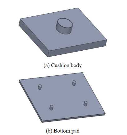 Figure 1 Rectangular air cushion isometric view
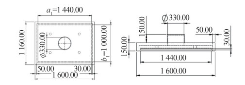 Figure 2 Rectangular air cushion geometric dimensions (mm)
The models of other geometric shapes according to the obtained dimensions in Table 1 are shown in Figures 3‒5.
Table 1 Calculated dimensions for different geometric shapesShape Cross-sectional area (1.44 m2) Obtained dimension (m) Square a22 a2 = 1.2 Equilateral triangle $\frac{\sqrt{3}}{4} a_3{ }^2 $ a3 = 1.823 6 Circle πR2 R = 0.677 Ellipse πa4b4 $ \left\{\begin{array}{c} a_4=1 \\ b_4=0.45837 \end{array}\right.$ Circle–Rectangle(a5 = 1.5b5) ${\pi {{\left({\frac{{{b_5}}}{2}} \right)}^2} + {a_5}{b_5}} $ ${\left\{ {\begin{array}{*{20}{l}} {{a_5} = 1.191}\\ {{b_5} = 0.794} \end{array}} \right.} $ Circle–Square $ {\pi {{\left({\frac{{{a_6}}}{2}} \right)}^2} + a_6^2}$ $ {{a_6} = 0.898}$ Hexagonal $ {6\frac{{\sqrt 3 }}{4}a_7^2}$ ${{a_7} = 0.7445} $ Fillet square (R' = a/n) $ \begin{array}{l} \pi {\left({\frac{a}{n}} \right)^2} + 4 \times \\ \left({\frac{a}{n}} \right)\left({\frac{{a(n - 2)}}{n}} \right) + \\ {\left({\frac{{a(n - 2)}}{n}} \right)^2} \end{array}$ ${a = \frac{{1.44{n^2}}}{{{n^2} - 4 + \pi }}} $ Fillet square (R' = a/4) $ \begin{array}{l} \pi {\left({\frac{{{a_8}}}{4}} \right)^2} + 4 \times \\ \left({\frac{{{a_8}}}{4}} \right)\left({\frac{{{a_8}}}{2}} \right) + {\left({\frac{{{a_8}}}{2}} \right)^2} \end{array}$ $ {a_8} = 1.2335\pi $ Fillet square (R' = a/8) $\begin{array}{l} {\left({\frac{{{a_9}}}{4}} \right)^2} + 4 \times \left({\frac{{{a_9}}}{8}} \right)\\ \left({\frac{{3{a_9}}}{4}} \right) + {\left({\frac{{3{a_9}}}{4}} \right)^2} \end{array} $ ${a_9} = 1.2081 $ 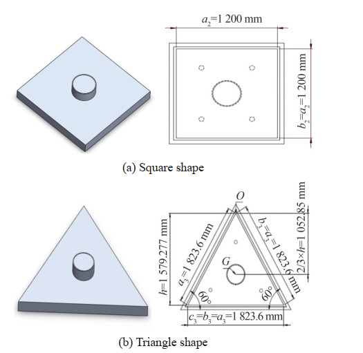 Figure 3 Modeling and geometric dimensions of triangle and square cushions
 Figure 4 Modeling and geometric dimensions of circular and elliptic cushions
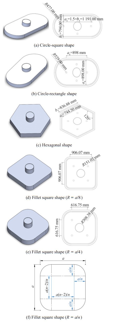 Figure 5 Modeling and geometric dimensions of combined cushions (circle-square, circle-rectangle, hexagonal, and fillet square (two cases R = a/4, R = a/8)) (a) Circular shape (b) Elliptic shape
3 Air cushion meshing and boundary conditions
After modeling the different shapes of the air cushions, we imported all designed models into ANSYS Fluent software for simulation analysis. Figure 6 shows the boundary conditions applied to all geometric shapes as well as the meshing process based on the symmetry plane view of each cushion. Figure 6 displays the fine meshing of elements in the border areas for the cushion and its inside.
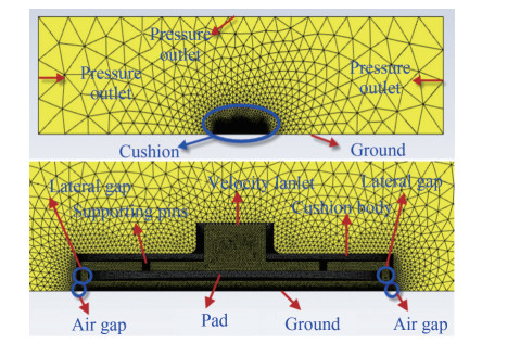 Figure 6 Meshing view of the symmetry plane of each cushion and governing boundary conditions
4 Simulation results and discussions
In this section, we will present the results for all shapes of air cushions. The numerical method of the solver used is the K - ε turbulence flow model.
4.1 Geometric shape effect
We simulated all nine geometric shapes based on the air gap changes between the cushion and the ground. We performed each simulation for a specific air gap. For example, some obtained simulation results for calculating the lift force of the two different circular and hexagonal cushion shapes are presented below.
The diagrams show that the lift force initially increased and almost converged to a fixed number by increasing the iteration. For all other simulations, we stopped problemsolving when the lift force converged to a constant value. Figures 9, 10 provide some of the obtained simulation results regarding the air pressure contour and the airflow path in the cushion.
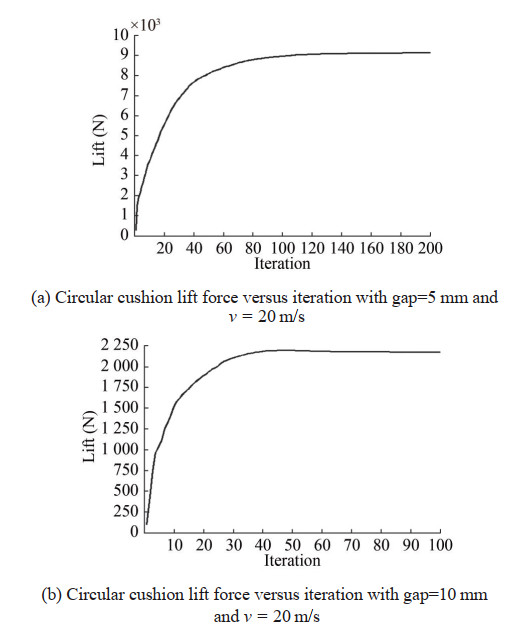 Figure 7 Circular cushion shape lift force calculation in terms of the number of solution iterations
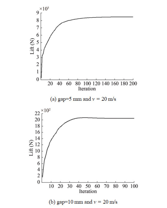 Figure 8 Hexagonal cushion shape lift force calculation in terms of the number of solution iterations
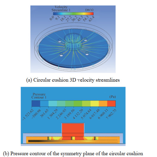 Figure 9 3D velocity streamlines and pressure contour of the circular cushion in gap = 6 mm and v = 20
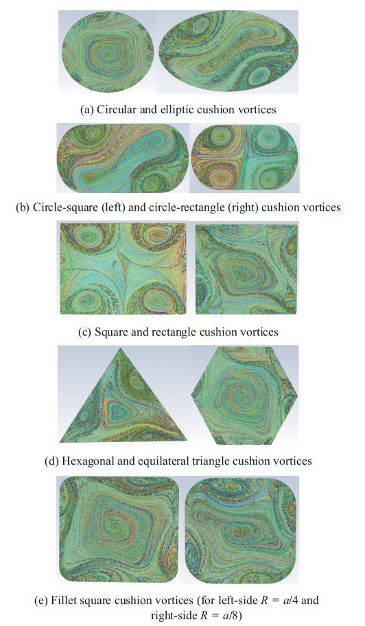 Figure 10 Flow pathlines under the pads with formed vortices in gap = 6 mm and v = 20 m/s
Figure 10 displays the airflow path with the formation of flow vortices at the bottom of the pad for different cushion shapes. Table 2 shows the obtained results from the lift force calculation for different gaps for all shapes with the inlet air velocity v = 20 m/s and the lateral gaps=30 mm.
Table 2 Lift force (N) of different shapes of the air cushions for different gapsShape Gap (mm) 3 4 5 6 7 8 9 10 Rectangular 20 687 11 483 7 258 5 025 3 670 2 774 2 179 1 744 Square 21 567 11 901 7 558 5 222 3 805 2 868 2 261 1 829 Fillet square (R = a/4) 24 465 13 581 8 574 5 913 4 312 3 275 2 573 2 070 Fillet square (R = a/8) 22 872 12 689 8 020 5 523 4 026 3 065 2 409 1 940 Triangular 16 342 9 060 5 731 3 954 2 889 2 194 1 718 1 379 Circular 25 976 14 412 9 126 6 289 4 590 3 489 2 730 2 201 Elliptic 21 351 11 776 7 493 5 175 3 778 2 836 2 245 1 812 Circle–rectangle 19 386 10 749 6 803 4 681 3 413 2 595 2 039 1 642 Circle–square 21 700 12 030 7 610 5 240 3 816 2 905 2 280 1 837 Hexagonal 24 391 13 522 8 550 5 886 4 293 3 263 2 563 2 064 Using curve fitting of data from Table 2, lift-gap diagrams of some cushions are presented as follows.
Examining all common curve fitting functions, including exponential, logarithmic, polynomial (with all orders), and power forms, we concluded that the power function is the best fitting with R2 = 1, where R2 is the Rsquared value in the data fitting regression model, and R2 = 1, indicating the best fitting. The obtained equations from the data power curve fitting function for all shapes are as follows:
$$ \text{Rectangular:} F(x)=196606 x^{-2.049}, R^2=1 \\ \text{Square:} F(x)=204871 x^{-2.05}, \quad R^2=1 \\ \text{Fillet square } \left(R=\frac{a}{8}\right): F(x)=217173 x^{-2.049}, R^2=1 \\ \text{Fillet square} \left(R=\frac{a}{4}\right): F(x)=232942 x^{-2.051}, R^2=1 \\ \text{Equilateral triangle:} F(x)=155630 x^{-2.051}, R^2=1 \\ \text{Circular: } F(x)=247101 x^{-2.05}, R^2=1 \\ \text{Elliptic: } F(x)=202535 x^{-2.049}, R^2=1 \\ \text{Circle-rectangle: } F(x)=184391 x^{-2.05}, R^2=1 \\ \text{Circle-square: }F(x)=205919 x^{-2.049}, R^2=1 \\ \text{Hexagonal: } F(x)=232127 x^{-2.051}, R^2=1 $$ (2) where F is the lift force (N), and x is the air gap (mm). Considering Eq. (2), the power of the x remained almost unchanged in all relations; hence, we assume F (x) = ax- 2.05 for all shapes. Now, we compare the results of the curves obtained from different velocities and lateral gaps to verify the approximate accuracy of this relation for other incoming air velocities.
Comparing different power curves for various shapes with different velocities and lateral gaps (with y symbol), we found again that the power of the x was almost unchanged. Therefore, the following equation (previously proposed) might be a good approximation for calculating the lift force in terms of the gap:
$$ F(x)=a x^{-2.05} $$ (3) where a is a coefficient whose value depends on inlet air velocity, lateral gaps, and geometric shape.
4.2 Lateral gaps
In this section, we investigate the effect of lateral gaps. Therefore, the lateral gaps for the four different geometric shapes were changed from 30 mm (primary) to 20 mm. The obtained results are shown in Figure 14 as follows:
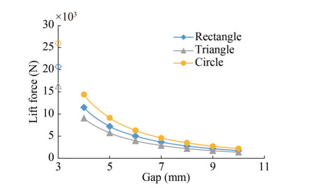 Figure 11 Lift-gap diagram of different cushion shapes with v = 20 m/s and lateral gaps = 30 mm
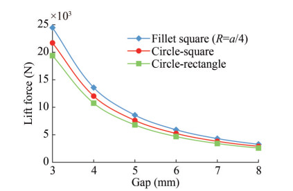 Figure 12 Lift-gap diagram of combined cushion shapes with v = 20 m/s and lateral gaps = 30 mm
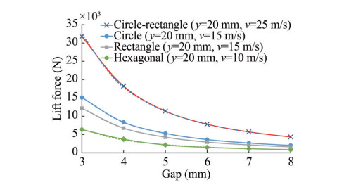 Figure 13 Lift-gap diagram of different cushions with different lateral gaps and velocities
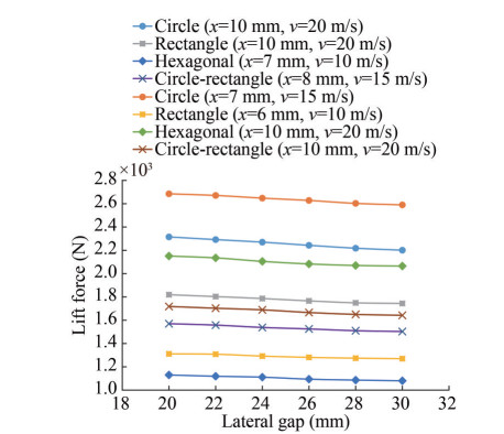 Figure 14 Lift-lateral gap diagram of different cushions with different gaps and velocities
Similar to the previous section, we examined the dependency of this parameter on other parameters. After exploring the different curve fitting methods, we selected the exponential function for analysis and formulation because of its simple form.
$$ \text { Circle }(x=10 \mathrm{~mm}, v=20 \mathrm{~m} / \mathrm{s}): F(y)=2899.1 e^{-0.004 y}, \\ R^2=0.9934 \\ \text { Circle }(x=7 \mathrm{~mm}, v=15 \mathrm{~m} / \mathrm{s}): F(y)=2568.4 e^{-0.005 y}, \\ R^2=0.9973 \\ \text { Rectangle }(x=10 \mathrm{~mm}, v=20 \mathrm{~m} / \mathrm{s}): F(y)=1987.9 e^{-0.004 y}, \\ R^2=0.9837 \\ \text{Rectangle}(x=6 \mathrm{~mm}, v=10 \mathrm{~m} / \mathrm{s}): F(y)=1407.8 e^{-0.004 y}, \\ R^2=0.9618 \\ \text{Hexagonal} (x=10 \mathrm{~mm}, v=20 \mathrm{~m} / \mathrm{s}): F(y)=2386.4 e^{-0.005 y}, \\ R^2=0.9821 \\ \text{Hexagonal }(x=7 \mathrm{~mm}, v=10 \mathrm{~m} / \mathrm{s}): F(y)=1237.6 e^{-0.005 y}, \\ R^2=0.9823 \\ \text{Circle-rectangle} (x=10 \mathrm{~mm}, v=20 \mathrm{~m} / \mathrm{s}): F(y)= 1890.9 e^{-0.005 y}, R^2=0.9879\\ \text{Circle-rectangle }(x=8 \mathrm{~mm}, v=15 \mathrm{~m} / \mathrm{s}): F(y)= 1719.8 e^{-0.005 y}, R^2=0.9874 $$ (4) According to Eq. (4), the exponential power value remained almost unchanged by varying the velocity and gap for each geometric shape. Therefore, we can describe the relationship between lift force and lateral gaps as follows:
$$ F(y)=b e^{-0.0045 y} $$ (5) where y is the lateral gaps (mm), and b is a coefficient whose value depends on the gap, velocity, and geometric shape. We chose the exponential power value (-0.004 5) as the mean value of the equations obtained.
4.3 Inlet air velocity
Another input parameter is the airflow velocity into the cushion channel. Checking the dependency of this parameter on the others, we simultaneously changed the gap and the lateral gaps for every cushion in different shapes. The following diagram shows the obtained results.
A trendline added to each curve and the selected power function as the best fit are presented as follows:
$$\text{Circle}(x=3 \mathrm{~mm}, y=30 \mathrm{~mm}): F(v)=67.964 v^{1.982}, R^2=1\\ \text{Circle} (x=6 \mathrm{~mm}, y=20 \mathrm{~mm}): F(v)=13.867 v^{1.9909}, R^2=1\\ \text{Square} (x=3 \mathrm{~mm}, y=30 \mathrm{~mm}): F(v)=56.054 v^{1.9835}, R^2=1\\ \text{Square} (x=6 \mathrm{~mm}, y=20 \mathrm{~mm}): F(v)=16.876 v^{1.9836}, R^2=1\\ \text{Circle-square} (x=4 \mathrm{~mm}, y=30 \mathrm{~mm}): F(v)=31.69 v^{1.9852}, \\ R^2=1 \\ \text{Circle-square} (x=8 \mathrm{~mm}, y=20 \mathrm{~mm}): F(v)=7.8842 v^{1.9869}, \\ R^2=1 \\ \text{Hexagonal} (x=7 \mathrm{~mm}, y=30 \mathrm{~mm}): F(v)=11.254 v^{1.9877}, \\ R^2=1 \\ \text{Hexagonal} (x=5 \mathrm{~mm}, y=20 \mathrm{~mm}): F(v)=22.746 v^{1.989}, \\ R^2=1 $$ (6) According to Eq. (6), the power value of v remained unchanged with varying gaps and lateral gaps. Therefore, we consider the following relationship with the average power for all air gaps and shapes:
$$ F(v)=c v^{1.985} $$ (7) where v is the air inlet velocity (m/s), and c is a coefficient whose value depends on the gap, lateral gaps, and geometric shape. We can convert the airflow velocity and mass flow rate using the following relationship:
$$v=\frac{\dot{m}}{\rho A} $$ (8) where ${\dot{m}} $ is the mass flow rate (kg/s), ρ is the air density (kg/m3), and A is the cross-sectional area of the inlet channel (m2).
4.4 SF
SF is the last parameter examined. This parameter is defined as a coefficient that determines the lift force of the geometric shape on different scales. Tables 3–6 present the obtained results for different shapes with various velocities.
Table 3 Circular cushion lift force (N) for different scales and gaps with v = 20 m/sScale Gap (mm) Lift ratio 3 5 7 10 1 (Primary) 25 776 9 126 4 590 2 181 1 1.25 63 373 22 254 11 166 5 340 $\approx\left(\frac{5}{4}\right)^4=2.4414 $ 1.5 134 890 46 263 23 085 10 961 $ \approx\left(\frac{3}{2}\right)^4=\frac{81}{16}=5.0625$ 0.5 1 585 550 282 138 $\approx\left(\frac{1}{2}\right)^4=\frac{1}{16}=0.0625 $ 0.75 8 019 2 770 1 455 690 $ \approx\left(\frac{3}{4}\right)^4=0.3164$ Table 4 Rectangular cushion lift force (N) for different scales and gaps with v = 15 m/sScale Gap (mm) Lift ratio 3 5 7 10 1 (Primary) 11 680 4 088 2 061 980 $ \approx\left(\frac{5}{4}\right)^4=2.4414$ 1.25 27 614 10 148 5 046 2 387 $\approx\left(\frac{3}{2}\right)^4=\frac{81}{16}=5.0625 $ 1.5 57 425 21 220 10 624 5 184 $ \approx\left(\frac{1}{2}\right)^4=\frac{1}{16}=0.0625$ 0.5 715 255 129 60 $ \approx\left(\frac{1}{2}\right)^4=\frac{1}{16}=0.0625$ 0.75 3 550 1 245 648 304 $ \approx\left(\frac{3}{4}\right)^4=0.3164$ Table 5 Hexagonal cushion lift force (N) for different scales and gaps with v = 10 m/sScale Gap (mm) Lift ratio 3 5 7 10 1 (Primary) 6 004 2 046 1 080 515 1 1.25 14 860 5 270 2 596 1 260 $ \approx\left(\frac{5}{4}\right)^4=2.4414 $ 1.5 30 780 10 740 5 420 2 620 $\approx\left(\frac{3}{2}\right)^4=\frac{81}{16}=5.0625 $ 0.5 374 130 66 34 $\approx\left(\frac{1}{2}\right)^4=\frac{1}{16}=0.0625 $ 0.75 1 906 662 328 163 $\approx\left(\frac{3}{4}\right)^4=0.3164 $ Table 6 Circle-rectangle cushion lift force (N) for different scales and gaps with v = 25 m/sScale Gap (mm) Lift ratio 3 5 7 10 1 (Primary) 31 695 10 938 5 251 2 623 1 1.25 75 146 26 550 12 856 6 224 $ \approx\left(\frac{5}{4}\right)^4=2.4414$ 1.5 161 858 54 001 27 386 13 125 $ \approx\left(\frac{3}{2}\right)^4=\frac{81}{16}=5.0625$ 0.5 1 897 651 318 175 $ \approx\left(\frac{1}{2}\right)^4=\frac{1}{16}=0.0625 $ 0.75 9 760 3 417 1 602 793 $ \approx\left(\frac{3}{4}\right)^4=0.3164$ Tables 3–6 show that the lift ratio is approximately equal to the fourth power of the SF. Therefore, we define the relationship between the lift force of the main dimensions and the scaled dimensions in terms of the SF as follows:
$$ F(\mathrm{SF})=F_0(\mathrm{SF})^4 $$ (9) where F0 is the primary cushion lift force (N). Eq. (9) has a computational error of less than 6% for all data in Tables 3–6, which were obtained using the trial-and-error method.
4.5 Lift force calculation formula
Eqs. (3), (5), and (7) show the relationship between lift force and air gap, lateral gaps, and incoming air velocity. The obtained relations indicated that the power value was not changed significantly for all variables. Therefore, the three equations can be combined, and the new relationship is as follows:
$$\left\{\begin{array}{l} F(x)=a x^{-2.05} \\ F(y)=b e^{-0.0045 y} \\ F(v)=c v^{1.985} \\ F(\mathrm{SF})=F_0(\mathrm{SF})^4 \end{array} \rightarrow F(x, y, v, \mathrm{SF})=\delta x^{-2.05} e^{-0.0045 y} v^{1.985}(\mathrm{SF})^4\right. $$ (10) Eq. (10) shows that the lift force is determined as a function of the gap (x), lateral gaps (y), inlet velocity (v), and SF. In Eq. (10), δ is a coefficient that depends only on the geometric shape. δ can be calculated by substituting one of the desired points from the lift-gap curves for each geometric shape. Thus, we can obtain δ for each shape as follows:
4.6 Research practical applications
After analyzing the effects of geometric shapes and determining the new approximate mathematical formula for the lift force of all proposed air cushions, some practical applications of the results obtained in this paper are described in this section to demonstrate the necessity of the present study. We analyzed different geometric shapes and found that the circular form is the best shape to create the highest lift force compared with the other patterns under equal conditions. This finding could be useful for designing air cushions in ACVs, especially hovercraft systems. In addition, this paper is the first to present a new approximate mathematical formula for the air cushion lift force in terms of parameters containing the inlet air velocity, air gap, lateral gaps, and SF, which can predict the aerodynamic lift force of ACVs in different cushion sizes, air gaps, and inlet air velocities.
Another modern and fast transportation system that uses air cushion technology is called Hyperloop, which was proposed by Elon Musk at the end of 2013. Musk presented the report "Hyperloop Alpha" and introduced this system (Musk, 2013). The report describes a semi-cylindrical ultra-high-speed vehicle called "Pod" moving into the low air pressure tubes and also presents air cushions for levitating the pod as an alternative to magnetic suspension. Thus far, several designed pods are levitated via air cushions (Sayan, 2016; Drexel University Hyperloop Team, 2017; Berkeley University Hyperloop Team, 2018; McGinniss, 2017).
5 Mesh dependency
We performed some other simulations with different mesh sizes to ensure the accuracy of the obtained results. In this regard, we employed three different sizes of mesh elements for the circular cushion as a typical geometric shape and examined the convergence conditions for all simulation data again. According to this point, the table below presents the numerical results.
We compared the results in Table 8 and found that the maximum difference between the lift force of the three mesh size cases has less than 6.5% error. Thus, we concluded that the obtained results are almost independent of the mesh size selection.
Table 7 Calculated δ value for each shapeShape δ Circle 739 Hexagonal 693 Circle-square 617 Circle-rectangle 551 Rectangle 586 Square 614 Fillet square $ \left(R=\frac{a}{8}\right)$ 651 Fillet square $ \left(R=\frac{a}{4}\right)$ 695 Equilateral triangle 463 Ellipse 608 Table 8 Mesh dependency results for circular cushion with v = 20 m/sGap (mm) Lift force (N) Mesh 1 (1 162 686 elements) Mesh 2 (1 772 121 elements) Mesh 3 (2 837 603 elements) Result error (%) 10 2 248 2 201 2 100 6.58 7 4 632 4 590 4 509 2.66 5 9 164 9 126 9 028 1.48 Table 9 Comparison of the lift force in different gaps and inlet velocitiesInput parameters Output parameter Gap (mm) Inlet velocity (m/s) Lift force (N) (Present research) Lift force (N) (Pavăl et al., 2018) Result error (%) 30 25 11 693 12 032 2.8 30 16 831 17 340 2.9 35 22 896 23 598 3 50 25 4 332 4 361 0.7 30 6 245 6 281 0.6 35 8 482 8 546 0.7 6 Case study verification
We compared the results with those obtained from a similar study by Pavăl et al. (2018) to further investigate the reliability and validity of the simulations performed in a specific case. They designed a large elliptical cushion for the hovercraft system. Figure 16 shows the model design with the following dimensions.
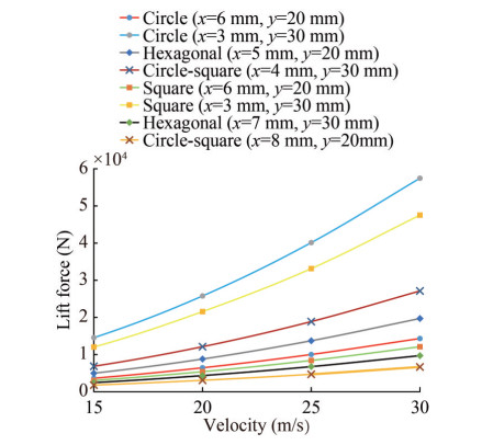 Figure 15 Lift-velocity diagram of different cushions with different gaps and lateral gaps
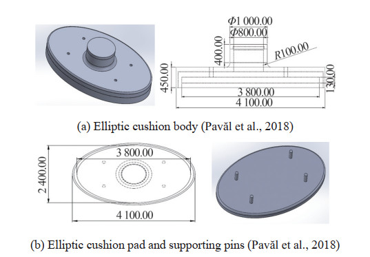 Figure 16 Hovercraft cushion model with dimensions
The obtained simulation results are compared with the results of Pavăl et al. (2018) as follows:
Comparing the obtained results with those of similar previous research, we found that the lift forces of both works are close to each other with less than 3% errors. This finding emphasizes the validity of the simulations performed in this study.
7 Conclusions
In this work, we innovatively studied the effect of geometric shape on air cushion lift force was innovatively studied using ANSYS Fluent software. To this end, we assumed nine different shapes for the cushion. We provided equal conditions for the simulation to investigate the effect of geometric shapes on lift force. Therefore, the cross-sections of all pads and other geometric dimensions were considered equal. The results showed that the cushion with a circular geometry has the highest lift force, and the equilateral triangle-shaped cushion has the lowest lift force. This study is the first to provide a new approximate mathematical relation for lift force in terms of parameters, including air gap, lateral gaps, inlet air velocity, and SF.
New investigations are conducted in the current research. However, limitations still exist, and suggestions can be presented to complete the work performed in this research. For example, in the present study, the ground surface is assumed to be completely smooth and flat, which can be considered uneven. Hence, the influence of ground surface roughness on the air cushion lift force can be investigated. Adding the forward speed of the vehicle to the system simulation and analyzing the effect of various forward speeds on the lift force is also possible. In addition, the system can be simulated using other different designs. For example, instead of using one hole (inlet channel) in the airflow inlet, a multi-hole system is considered, and the effect of hole number on the lift force is investigated.
Competing interest The authors have no competing interests to declare that are relevant to the content of this article. -
Figure 1 Rectangular air cushion isometric view
Figure 2 Rectangular air cushion geometric dimensions (mm)
Figure 3 Modeling and geometric dimensions of triangle and square cushions
Figure 4 Modeling and geometric dimensions of circular and elliptic cushions
Figure 5 Modeling and geometric dimensions of combined cushions (circle-square, circle-rectangle, hexagonal, and fillet square (two cases R = a/4, R = a/8)) (a) Circular shape (b) Elliptic shape
Figure 6 Meshing view of the symmetry plane of each cushion and governing boundary conditions
Figure 7 Circular cushion shape lift force calculation in terms of the number of solution iterations
Figure 8 Hexagonal cushion shape lift force calculation in terms of the number of solution iterations
Figure 9 3D velocity streamlines and pressure contour of the circular cushion in gap = 6 mm and v = 20
Figure 10 Flow pathlines under the pads with formed vortices in gap = 6 mm and v = 20 m/s
Figure 11 Lift-gap diagram of different cushion shapes with v = 20 m/s and lateral gaps = 30 mm
Figure 12 Lift-gap diagram of combined cushion shapes with v = 20 m/s and lateral gaps = 30 mm
Figure 13 Lift-gap diagram of different cushions with different lateral gaps and velocities
Figure 14 Lift-lateral gap diagram of different cushions with different gaps and velocities
Figure 15 Lift-velocity diagram of different cushions with different gaps and lateral gaps
Figure 16 Hovercraft cushion model with dimensions
Table 1 Calculated dimensions for different geometric shapes
Shape Cross-sectional area (1.44 m2) Obtained dimension (m) Square a22 a2 = 1.2 Equilateral triangle $\frac{\sqrt{3}}{4} a_3{ }^2 $ a3 = 1.823 6 Circle πR2 R = 0.677 Ellipse πa4b4 $ \left\{\begin{array}{c} a_4=1 \\ b_4=0.45837 \end{array}\right.$ Circle–Rectangle(a5 = 1.5b5) ${\pi {{\left({\frac{{{b_5}}}{2}} \right)}^2} + {a_5}{b_5}} $ ${\left\{ {\begin{array}{*{20}{l}} {{a_5} = 1.191}\\ {{b_5} = 0.794} \end{array}} \right.} $ Circle–Square $ {\pi {{\left({\frac{{{a_6}}}{2}} \right)}^2} + a_6^2}$ $ {{a_6} = 0.898}$ Hexagonal $ {6\frac{{\sqrt 3 }}{4}a_7^2}$ ${{a_7} = 0.7445} $ Fillet square (R' = a/n) $ \begin{array}{l} \pi {\left({\frac{a}{n}} \right)^2} + 4 \times \\ \left({\frac{a}{n}} \right)\left({\frac{{a(n - 2)}}{n}} \right) + \\ {\left({\frac{{a(n - 2)}}{n}} \right)^2} \end{array}$ ${a = \frac{{1.44{n^2}}}{{{n^2} - 4 + \pi }}} $ Fillet square (R' = a/4) $ \begin{array}{l} \pi {\left({\frac{{{a_8}}}{4}} \right)^2} + 4 \times \\ \left({\frac{{{a_8}}}{4}} \right)\left({\frac{{{a_8}}}{2}} \right) + {\left({\frac{{{a_8}}}{2}} \right)^2} \end{array}$ $ {a_8} = 1.2335\pi $ Fillet square (R' = a/8) $\begin{array}{l} {\left({\frac{{{a_9}}}{4}} \right)^2} + 4 \times \left({\frac{{{a_9}}}{8}} \right)\\ \left({\frac{{3{a_9}}}{4}} \right) + {\left({\frac{{3{a_9}}}{4}} \right)^2} \end{array} $ ${a_9} = 1.2081 $ Table 2 Lift force (N) of different shapes of the air cushions for different gaps
Shape Gap (mm) 3 4 5 6 7 8 9 10 Rectangular 20 687 11 483 7 258 5 025 3 670 2 774 2 179 1 744 Square 21 567 11 901 7 558 5 222 3 805 2 868 2 261 1 829 Fillet square (R = a/4) 24 465 13 581 8 574 5 913 4 312 3 275 2 573 2 070 Fillet square (R = a/8) 22 872 12 689 8 020 5 523 4 026 3 065 2 409 1 940 Triangular 16 342 9 060 5 731 3 954 2 889 2 194 1 718 1 379 Circular 25 976 14 412 9 126 6 289 4 590 3 489 2 730 2 201 Elliptic 21 351 11 776 7 493 5 175 3 778 2 836 2 245 1 812 Circle–rectangle 19 386 10 749 6 803 4 681 3 413 2 595 2 039 1 642 Circle–square 21 700 12 030 7 610 5 240 3 816 2 905 2 280 1 837 Hexagonal 24 391 13 522 8 550 5 886 4 293 3 263 2 563 2 064 Table 3 Circular cushion lift force (N) for different scales and gaps with v = 20 m/s
Scale Gap (mm) Lift ratio 3 5 7 10 1 (Primary) 25 776 9 126 4 590 2 181 1 1.25 63 373 22 254 11 166 5 340 $\approx\left(\frac{5}{4}\right)^4=2.4414 $ 1.5 134 890 46 263 23 085 10 961 $ \approx\left(\frac{3}{2}\right)^4=\frac{81}{16}=5.0625$ 0.5 1 585 550 282 138 $\approx\left(\frac{1}{2}\right)^4=\frac{1}{16}=0.0625 $ 0.75 8 019 2 770 1 455 690 $ \approx\left(\frac{3}{4}\right)^4=0.3164$ Table 4 Rectangular cushion lift force (N) for different scales and gaps with v = 15 m/s
Scale Gap (mm) Lift ratio 3 5 7 10 1 (Primary) 11 680 4 088 2 061 980 $ \approx\left(\frac{5}{4}\right)^4=2.4414$ 1.25 27 614 10 148 5 046 2 387 $\approx\left(\frac{3}{2}\right)^4=\frac{81}{16}=5.0625 $ 1.5 57 425 21 220 10 624 5 184 $ \approx\left(\frac{1}{2}\right)^4=\frac{1}{16}=0.0625$ 0.5 715 255 129 60 $ \approx\left(\frac{1}{2}\right)^4=\frac{1}{16}=0.0625$ 0.75 3 550 1 245 648 304 $ \approx\left(\frac{3}{4}\right)^4=0.3164$ Table 5 Hexagonal cushion lift force (N) for different scales and gaps with v = 10 m/s
Scale Gap (mm) Lift ratio 3 5 7 10 1 (Primary) 6 004 2 046 1 080 515 1 1.25 14 860 5 270 2 596 1 260 $ \approx\left(\frac{5}{4}\right)^4=2.4414 $ 1.5 30 780 10 740 5 420 2 620 $\approx\left(\frac{3}{2}\right)^4=\frac{81}{16}=5.0625 $ 0.5 374 130 66 34 $\approx\left(\frac{1}{2}\right)^4=\frac{1}{16}=0.0625 $ 0.75 1 906 662 328 163 $\approx\left(\frac{3}{4}\right)^4=0.3164 $ Table 6 Circle-rectangle cushion lift force (N) for different scales and gaps with v = 25 m/s
Scale Gap (mm) Lift ratio 3 5 7 10 1 (Primary) 31 695 10 938 5 251 2 623 1 1.25 75 146 26 550 12 856 6 224 $ \approx\left(\frac{5}{4}\right)^4=2.4414$ 1.5 161 858 54 001 27 386 13 125 $ \approx\left(\frac{3}{2}\right)^4=\frac{81}{16}=5.0625$ 0.5 1 897 651 318 175 $ \approx\left(\frac{1}{2}\right)^4=\frac{1}{16}=0.0625 $ 0.75 9 760 3 417 1 602 793 $ \approx\left(\frac{3}{4}\right)^4=0.3164$ Table 7 Calculated δ value for each shape
Shape δ Circle 739 Hexagonal 693 Circle-square 617 Circle-rectangle 551 Rectangle 586 Square 614 Fillet square $ \left(R=\frac{a}{8}\right)$ 651 Fillet square $ \left(R=\frac{a}{4}\right)$ 695 Equilateral triangle 463 Ellipse 608 Table 8 Mesh dependency results for circular cushion with v = 20 m/s
Gap (mm) Lift force (N) Mesh 1 (1 162 686 elements) Mesh 2 (1 772 121 elements) Mesh 3 (2 837 603 elements) Result error (%) 10 2 248 2 201 2 100 6.58 7 4 632 4 590 4 509 2.66 5 9 164 9 126 9 028 1.48 Table 9 Comparison of the lift force in different gaps and inlet velocities
Input parameters Output parameter Gap (mm) Inlet velocity (m/s) Lift force (N) (Present research) Lift force (N) (Pavăl et al., 2018) Result error (%) 30 25 11 693 12 032 2.8 30 16 831 17 340 2.9 35 22 896 23 598 3 50 25 4 332 4 361 0.7 30 6 245 6 281 0.6 35 8 482 8 546 0.7 -
Ai T, Fan W, Xu B, Xiang C, Zhang Y, Zhao Z (2021) Aerodynamic analysis and modeling of coaxial ducted fan aircraft with the ceiling effect. Engineering Applications of Computational Fluid Mechanics 15(1): 1563–1584 https://doi.org/10.1080/19942060.2021.1984311 Berkeley University Hyperloop Team (2018) SpaceX Hyperloop Pod Competition. Available from https://hypershot.berkeley.edu/ [Accessed on Nov. 29, 2023] Chang Y, Moretti P (1999) Aerodynamic characteristics of pressure-pad air bars. J Appl Mech. 67(1): 177–182 https://doi.org/10.1115/1.321161 Chen XD, He XM (2006) The effect of the recess shape on performance analysis of the gas-lubricated bearing in optical lithography. Tribology International 39: 1336–1341 https://doi.org/10.1016/j.triboint.2005.10.005 Cole RE, Neu WL (2019) Validation of a commercial fluid-structure interaction solver with applications to air cushion vehicle flexible seals. Ocean Engineering 189: 106287 https://doi.org/10.1016/j.oceaneng.2019.106287 Drexel Unversity Hyperloop Team (2017) SpaceX Hyperloop Pod Competition. Available from https://research.coe.drexel.edu/mem/dssl/hyperloop/aboutus/ [Accessed on Nov. 29, 2023] Jiang Y, Tang W (2022) Numerical investigation on water entry of a three-dimensional flexible bag of an air cushion vehicle. Ocean Engineering 247: 110653 https://doi.org/10.1016/j.oceaneng.2022.110653 Kaya K, Özcan O (2013) A numerical investigation on aerodynamic characteristics of an air-cushion vehicle. Journal of Wind Engineering and Industrial Aerodynamics 120: 70–80 https://doi.org/10.1016/j.jweia.2013.06.012 Li N, Liu Y, Gao J, Huang Z, Wang L (2022) Aerodynamic damping and amplitude response of piezoelectric fans in free and confined space. Engineering Applications of Computational Fluid Mechanics 16(1): 161–176 https://doi.org/10.1080/19942060.2021.2005683 Li Y, Li J, Ling X, Wang Z, Fu T, Han Y (2017) Optimization and aerodynamic characteristics of new air-cushion nozzle of floating furnace for automobile body sheet. Journal of Harbin Institute of Technology (New Series) 24(1): 57–64 Lu Y, Li Z, Chang X, Chuang Z, Xing J (2021) An aerodynamic optimization design study on the bio-inspired airfoil with leading-edge tubercles. Engineering Applications of Computational Fluid Mechanics 15(1): 292–312 https://doi.org/10.1080/19942060.2020.1856723 Martins JRRA (2022) Aerodynamic design optimization: Challenges and perspectives. Computers & Fluids 239: 105391 https://doi.org/10.1016/j.compfluid.2022.105391 McGinniss JR (2017) System design of a high speed ground vehicle lifted by air bearings. Master thesis, University of Texas at Austin Musk E (2013) Hyperloop Alpha. SpaceX: Hawthorne, USA. Available from https://www.tesla.com/sites/default/files/blog_images/hyperloop-alpha.pdf [Accessed on Nov. 29, 2023] Pavăl M, Popescu A, Popescu T, Zahariea D, Husaru D (2018) Numerical study on the movement of air inside the inner cavity of a hovercraft model. Proceedings of the IOP Conference Series: Materials Science and Engineering 444(8): 082005 https://doi.org/10.1088/1757-899X/444/8/082005 Pavăl M, Popescu A, Zahariea D (2019) Numerical analysis of the influence of the lower hull angle of a round skirtless air cushion vehicle. Proceedings of the IOP Conference Series: Materials Science and Engineering 595(1): 012049 https://doi.org/10.1088/1757-899X/595/1/012049 Pavăl M, Popescu A, Zahariea D (2020a) CFD analysis of a round shaped air cushion vehicle with flexible skirt segments at 90° and different air clearance height. Proceedings of the IOP Conference Series: Materials Science and Engineering 68(3): 137–150 Pavăl M, Popescu A, Zahariea D (2020b) CFD analysis of a round shaped air cushion vehicle with inclined skirt segments. Proceedings of the IOP Conference Series: Materials Science and Engineering 997(1): 012152 https://doi.org/10.1088/1757-899X/997/1/012152 Sadeghi H, Pourfallah M, Molla-Alipour M, Darzi AR (2020) Numerical investigation of lift force increase in a hovercraft by changing the geometrical parameters of flow transfer part and air channel. Journal of Marine Engineering 15(30): 81–92 https://doi.org/10.29252/marineeng.15.30.81 Saeid NH, Yunus E, Fei OC (2014) CFD simulation of air flow around a hovercraft. 5th Brunei International Conference on Engineering and Technology (BICET 2014), 39(11): 1336–1341 Sayan RKS, Walter M, Michael F, Rohan D (2016) Georgia Hyperloop Team Final Pod Design Briefing. SpaceX Hyperloop Design Competition. Available from GT Hyperloop Pod Final Design Briefing Presentation ∣ PPT (slideshare. net) [Accessed on Nov. 29, 2023] Siddique PMMA, Raj LP (2023) Sensitivity analysis of geometric parameters on the aerodynamic performance of a multi-element airfoil. Aerospace Science and Technology 132: 108074 https://doi.org/10.1016/j.ast.2022.108074 Soltaninejad M, Azarsina F, Javid A (2015) Analysis of air injection system for drag reduction in high speed vessels using numerical simulation software ANSYS-Fluid flow. International Journal of Marine Science and Engineering 5(2): 65–75 Williams A, Collu M, Patel MH (2010) Aerodynamic lift forces on multihulled marine vehicles. International Journal of Maritime Engineering 152(A2-June): A-41 Xu S, Chen K, Tang Y, Xiong Y, Ma T, Tang W (2021) Research on the transverse stability of an air cushion vehicle hovering over the rigid ground. Ships and Offshore Structures 17(10): 2300–2316 https://doi.org/10.1080/17445302.2021.1985825
