
Fuel Consumption Analysis of Single and Twin-Screw Propulsion Systems of a Bulk Carrier
https://doi.org/10.1007/s11804-023-00372-4
-
Abstract
This paper presents a comparative analysis between single and twin-screw propulsion systems of a bulk carrier to evaluate the ship and propeller performance in terms of fuel consumption as well as to discuss the cavitation and noise criteria. An optimization model is developed to select the optimum propeller geometry and operational point along the engine load diagram for the selected engines of each case. The engines are selected from the same series due to the same behaviour along the engine load diagram. The propellers are selected from the B-series as fixed-pitch propellers. It has been concluded that while the components of the single-screw propulsion system are larger than the twin-screw, the single-screw propulsion system shows a reduction in fuel consumption than the twin screw by around 19%, thus affecting the amount of exhaust emissions from the ship. This model helps the ship designers to select a suitable propeller to improve the energy efficiency of the ships.-
Keywords:
- Propeller performance ·
- Exhaust emissions ·
- Energy efficiency ·
- IMO ·
- Decarbonization ·
- Fuel consumption ·
- Single and twin-screw
Article Highlights• A comparative analysis between single and twin-screw propulsion systems of a bulk carrier is performed.• An optimization model is developed to select the optimum propeller geometry and operational point along the engine load diagram.• The single-screw propulsion system shows a reduction in fuel consumption than the twin screw by around 19%.• The developed model helps in the selection of a suitable propeller. -
1 Introduction
According to the new stringent regulations issued by the International Maritime Organization (IMO), several technologies have been suggested and developed to reduce the amount of power required to operate the ships (Mallouppas and Yfantis, 2021; Tadros et al., 2023) for instance, optimizing hull shape (Nazemian and Ghadimi, 2021), integration of air lubrication technologies (Hao, 2019), benefiting from wind energy (Seddiek and Ammar, 2021) and reduction of ship speed (Taskar et al., 2023). The selection of a suitable propulsion system during the preliminary stages of ship design is another concept and becomes an essential process (El-Gohary, 2013) to ensure the safety of the ship during the trip as well as the operation of the ship with the lowest amount of fuel onboard (Vettor et al., 2016; Zaccone et al., 2018; Moreira et al., 2021). This procedure directly affects the operation cost of the ship along the life span, which decreases the amount of fuel consumed and thus increases the percentage of the profit of the ship owner (Du et al., 2022). This procedure is not specific to marine diesel oil, which shows an increment in the fuel price nowadays, as shown in Figure 1, but also for the other new type of fuels (El Gohary and Ammar, 2016; Karatuğ et al., 2022), including those that will be available in the market shortly, such as hydrogen, biofuel, ammonia and methanol (El-Gohary et al., 2014; Chiong et al., 2021; Tadros et al., 2021b; Vedachalam et al., 2022).
 Figure 1 Average price at top 20 bunker ports (Miller, 2022)
The typical propulsion system of large ships is composed of the marine diesel engine coupled to a propeller through the propeller shaft and gearbox in the case of a four-stroke engine, and without a gearbox in the case of a two-stroke engine, thus various models are developed to be available to simulate their performance (Nahim et al., 2015; Altosole et al., 2017; Tadros et al., 2020a).
In addition to the engine, the different types of propellers (Zainol and Yaakob, 2016; Najafi and Pourmostafa, 2022) have been well designed due to the fast rapid technology that allows high-accuracy models during production and provides more control during different operational conditions.
Regarding the main source of power, the diesel engine, engines with high performance are already available in the market from different manufacturers to produce the required power supporting the ship's needs to achieve a certain speed. The efficiency of the new engines has been increased due to the control procedures applied on the different parts of the engine and thus achieving more than 50%, showing a good increment compared to the old engines (Wartsila, 2023). The new engines have been optimized to reduce the amount of brake-specific fuel consumption (BSFC) for each operating point (Tadros et al., 2019; Tadros et al., 2020b; Stoumpos and Theotokatos, 2020; Figari et al., 2022; Xiang et al., 2023). Thus, these types of procedures allow the engines to comply with the stringent regulations of international organizations towards mitigating climate change (Latarche, 2020).
These types of control are implemented in developing high-performance turbocharger(s) and intercoolers and providing control to the intake and exhaust valves (Wei et al., 2019; Wei et al., 2022), injection systems (Raeie et al., 2014; Tadros et al., 2020a) and exhaust gas recirculation (EGR) (Wang et al., 2021). The recuperation of the exhaust heat is seen in several solutions (Cherednichenko and Mitienkova, 2020; Cherednichenko and Serbin, 2018; Tadros et al., 2021c).
The main concept of implementing these types of controls is to increase the amount of intake air inside the cylinders accompanied by the perfect injection timing, which will reduce the amount of fuel consumption and the level of exhaust emissions (Zetterdahl et al., 2017; Tadros et al., 2020b; Fridell et al., 2021; Mocerino et al., 2021). Therefore, the development of several numerical models easily assists in the computation procedures to take the optimal decision and achieve highly accurate models, ensuring the sustainability of the propulsion systems (Benvenuto et al., 2021; Benvenuto and Campora, 2022; Trivyza et al., 2022). These models can vary from the look-up table to the complex computational fluid dynamics (CFD) depending on the required level of detail of the computed results.
Regarding the propulsor, several profiles of propellers have been developed to be used according to the application. The selection of an appropriate propeller(s) from the given series is important to ensure the generation of the required thrust to the ship. Also, it is crucial to take into consideration the criteria of cavitation, noise and strength (Carlton, 2012). For instance, Wageningen B-Series (Van Lammeren et al., 1969) has been widely used in commercial ships equipped with fixed-pitch propellers (FPP). However, by the increased demand for controllable-pitch propellers (CPP) to provide more control to the ship, Wageningen Propeller C- and D-Series have been developed and taking place to serve the market demands (Dang et al., 2013).
Recently, the Wageningen F-series (Huisman et al., 2021) has been designed to provide the highest efficiency and compliance with cavitation limits for the merchant's vessels. The propeller is usually designed at the maximum propeller efficiency (Hong et al., 2014), while the selection of a propeller at the engine operating point with minimum fuel consumption and power management can achieve a higher reduction in fuel consumption, either with a fixed pitch (Vesting and Bensow, 2018; Arapakopoulos et al., 2019; Tadros et al., 2021a), a controllable pitch propeller (Jaurola et al., 2020; Bacciaglia et al., 2021; Tadros et al., 2022b) or contra-rotating propeller (Nouri et al., 2018; Tadros et al., 2022c). In addition, applying several modifications to the propeller, such as the cupping percentage (Hwang et al., 1995; Tadros et al., 2022e), boss cap fins (Xiong et al., 2013) or installing energy devices before or after the propeller (Stark et al., 2022) will help to improve the wake flow and thus increase the propeller performance.
From the concept of design, designers need to select the optimal number of propulsion systems, including the number of engines and propellers. The single-screw propulsion has an advantage over twin-screw propulsion as it is simpler and consists of only one engine and one propeller. However, the engine and propeller can be bigger to produce the required power and thrust for the ship, therefore the loads on this system are larger than on the twin screw propulsion system. On the other hand, the twin screw is more complex, where the number of each part of the propulsion system is doubled, as well as the initial cost, in addition to the hull modification by adding a twin-skeg to support the propulsion system (Williams, 1975; Kim et al., 2014). However, the engine and propeller size are smaller than the single screw propulsion, and the loads are distributed along the two propulsion systems. Also, it shows an advantage in emergencies as the ship can operate with one of the two lines of the propulsion system until reaching the nearest safe port.
Usually, small ships with higher speeds require more than a single propulsion system due to the limitations of the stern part and stability computations to install a large engine with only one propeller and achieve the required speed. Therefore, the twin-screw propulsion system will be more effective than the single one. On the other hand, selecting the number of propulsion systems in large ships becomes more difficult as the ship can operate effectively using both systems (single and twin-screw).
However, due to international regulations and increments in fuel prices, it is beneficial to select the optimum propulsion system to ensure the lowest fuel consumption. To the authors' knowledge, the research works already published and mentioned in the literature review mainly focus on determining the amount of power required and the reduction of the installed engine loading ratio without comparing the amount of fuel consumed between the different configurations. This is due to the lack of fuel consumption information along the engine load diagram.
Therefore, this paper used the data of engine performance previously calculated using engine simulation software to present a comparative analysis between the single and twin-screw propulsion systems of a bulk carrier to evaluate the ship and propeller performance in terms of fuel consumption as well as discuss the cavitation and noise criteria. The computations are performed based on the propeller geometry of each case that is designed using optimization procedures and has been selected to minimize fuel consumption.
The remainder of this paper is organized as follows. The main characteristics of the bulk carrier are presented in Section 2. Next, the numerical model used to perform the simulation is described in section 3. The discussion of the computed results is presented in section 4. Finally, a summary of the main findings and future recommendations are presented in Section 5.
2 Main characteristics of the bulk carrier
This study considers the selection of a bulk carrier's single and twin screw propellers from B-series as an FPP depending on the number and rated power of the engine(s). The ship is 154 m in length and can sail at 14.5 kn. The ship is operated by a four-stroke marine diesel engine(s) from the series of MAN 32/44CR, where each cylinder's power is 510 kW, and the engine's total power differs according to the number of cylinders. The main characteristics of the ship and the engine are presented in Tables 1 and 2, respectively.
Table 1 Main characteristics of the bulk carrierCharacteristics Value Length waterline (m) 154.00 Breadth (m) 23.11 Draft (m) 10.00 Displacement (t) 27 690 Service speed (kn) 14.5 Maximum speed (kn) 16.0 Type of propellers FPP Rated power (kW) 7 140 Table 2 Main characteristics of the diesel engineCharacteristics Value Engine builder MAN energy solutions Brand name MAN Bore (mm) 320 Stroke (mm) 440 Rated speed (r/min) 750 Rated power per cylinder (kW) 510 3 Numerical model
The computation of each case is performed using a developed optimization model coupling NavCad (HydroComp, 2018) and an optimizer implemented in Matlab to select the optimum propeller geometry and the operational point of the propeller inside the engine load diagram for a given ship speed (Vs) and the number of propeller blades (Z). This model allows operational research techniques to find the optimal values of the design variables of the propeller while minimizing the fuel consumption as the main objective of the model and complying with the limitations of several criteria as constraints, such as cavitation and noise. The design variables include propeller diameter (D), expanded area ratio (EAR), pitch diameter ratio (P/D) and gearbox ratio (GBR). Figure 2 shows a schematic diagram of the developed optimization model that is used in this study, coupling the different software components and showing the different variables and the output results of the optimization model.
 Figure 2 Schematic diagram of the developed optimization model (Tadros et al., 2021d)
In general, the optimization model based on the fmincon function can find the minimum of the problem specified by:
$$ \min\limits_x f(x) \text { such that }\left\{\begin{array}{l} c(x) \leqslant 0 \\ c_{\mathrm{eq}}(x)=0 \\ A \cdot x \leqslant b \\ A_{\mathrm{eq}} \cdot x=b_{\mathrm{eq}} \\ l b \leqslant x \leqslant u b \end{array}\right. $$ (1) where f(x) is the objective of the optimization model, x is the optimization variables, c is the inequality constraints, ceq is the equality constraints, A as a matrix and b as a vector are the linear inequality constraints, Aeq as a matrix and beq as a vector are the linear equality constraints, and lb and ub are the lower and upper bounds, respectively.
This model is slightly converted, where the objective and constraints are defined into one single function called the fitness function. This conversion is performed to reduce the time of simulation combining all the computed results into one equation and evaluated by the optimizer as in the following equation.
$$ \text { Fitness Function }=\mathrm{FC}_{\mathrm{kg} / \mathrm{nm}}+R \sum\limits_{i=1}^j \max \left(g_i(x), 0\right) $$ (2) where R is a constant, g is the penalty function presenting the constraints, and j is the number of constraints.
The fuel consumption, FC, is computed using the following expression:
$$ \mathrm{FC}_{\mathrm{kg} / \mathrm{nm}}=\frac{\mathrm{BSFC} \times P_B \times 1000}{V_S} $$ (3) where PB is the brake power.
The first step of the model is to compute the ship resistance by defining all the required variables into the software to be implemented into the numerical equations presented by Holtrop (1984) and Holtrop (1988) as the suggested method by NavCad, which comply with the ship type and dimensions. This method shows good computational accuracy in the estimation of the ship resistance for several ship speeds (Gaafary et al., 2011; Elkafas et al., 2019; Islam et al., 2022) and ship conditions (Islam and Guedes Soares, 2019). After defining all the ship parameters and operational speed, the total ship resistance is computed, as shown in Figure 3, as a summation of the bare-hull resistance and marginal resistance taking into account the roughness of a clean hull (Tadros et al., 2022d). The marginal resistance is used to predict an appropriate value of the resistance as a percentage of the bare-hull resistance. The value used in this study is 10% and corresponds to the feasibility estimation.
 Figure 3 Total ship resistance for different ship speeds
Once the resistance is computed, the simulation is then moved to compute the propulsion system as the second step. The method by Holtrop and Mennen (1982) is considered to compute the propulsive coefficient to evaluate the wake fraction (w), thrust deduction fraction (t) and relative rotative efficiency (ηRR), which differs from single and twin-screw. The main important parameters required in this step are the selection of propeller series, maximum propeller diameter, rated engine power and speed and the gearbox and propeller shaft efficiencies.
The value of these parameters differs for each case suggested in this study, and they will be presented in detail in section 4. After defining all the variables, the ship power, the propulsive coefficients, the operation of the engine(s) and propeller(s), as well as the cavitation and noise criteria are computed. The main characteristics of the propeller, such as the advance coefficient (JA), thrust coefficient (KT), torque coefficient (KQ) and open water efficiency (ηo) are computed. The cavitation is evaluated by the method of Keller (1973) to compute the minimum EAR, Burrill and Emerson (1963) to compute the average loading pressure, Blount and Fox (1978) to calculate the average predicted back cavitation percentage and the minimum pitch as suggested by MacPherson (1991) to avoid face cavitation. The noise is computed based on the tip speed and the limits are provided in the manual of HydroComp (2018). More information about the methods and the limits of each criterion is presented in detail by Tadros et al. (2022a).
4 Results and discussion
In order to perform the comparison between the two cases, the simulation is performed twice, and the results are exported for each case. The first case concerns the simulation of the performance of a single-screw propulsion system, and in the second one, the performance of a twin-screw propulsion system is simulated. In both cases, the hull is assumed to be the same, and the total resistance is kept the same, as the difference between the two cases is the modification of the stern by adding another skeg in the second case, which can increase the wetted surface by a small amount than the first case. Therefore, it is preferable to keep the use of the same hull with the same resistance for comparison.
The engines from the same series MAN 32/44 CR are selected as they have the same performance along the engine load diagram, even if the number of cylinders is changed.
In the first case, the engine with fourteen cylinders is selected, providing 7 140 kW brake power and coupled with an FPP. In the second case, two engines with seven cylinders each are selected, each one able to produce 3 570 kW, and coupled as well to an FPP. The maximum diameter in each case is selected according to the shape of the stern. The maximum diameter in the first case is 60% of the ship draft, and the maximum diameter of each FPP in the second case is 50% of the ship draft. This maximum value is used to define the upper boundary of the optimization model, while the lower boundary is defined by 80% of the upper boundary.
Once all the parameters are defined, the input data are processed into the optimization model and thus going through NavCad using the premium feature; then the results are computed and exported into Excel spreadsheet files, which have been collected to evaluate the fitness function to reduce the fuel consumption as in equation (3) and comply with all the limit values of the constraints defined. The numerical optimized results are presented in Table A1 for more information, while the results are normalized in Figures 4 to 6 to provide a clear comparison between the two cases.
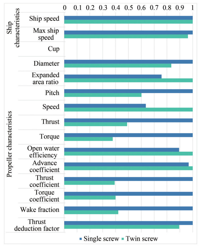 Figure 4 Ship and propeller characteristics of each calculated case
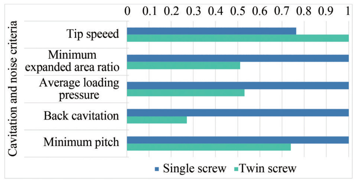 Figure 5 Cavitation and noise criteria of each calculated case
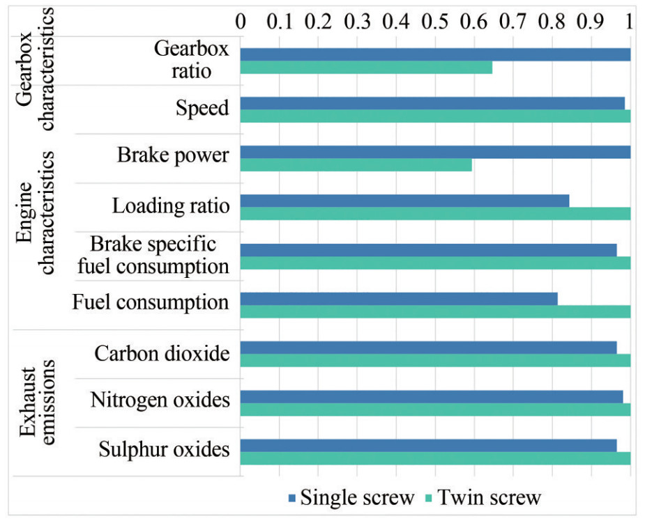 Figure 6 Gearbox and engine characteristics as well as exhaust emissions of each calculated case
Regarding the ship characteristics, as shown in Figure 4, it has been shown that the two propulsion systems can provide the required thrust to operate the ship smoothly at 14.5 kn as service speeds. However, the single screw can allow the ship to reach 16 kn with more than 5% in the case of the twin screw. This is due to the larger diameter that is installed in the first case compared to the second one. Otherwise, larger engines in the second case can replace the suggested ones to allow the ship to reach the same maximum speed as in the first case. Engines with eight cylinders can be selected to produce 4 080 kW to achieve the top speed, and thus the propeller can be designed to operate at lower loads and thus reduce fuel consumption.
Regarding the propeller characteristics, the propeller diameter is always selected at the upper boundary limits (6 m for the single screw and 5 m for the twin screw). This parameter shows its importance in increasing the propeller efficiency compared to the same propeller with lower diameter, and the propeller can produce the required thrust at lower engine loads. It has been shown that the propeller thrust in the twin screw is a little bit lower than half of the single screw to achieve the same ship speed due to the propulsive coefficient calculations, in particular, the thrust deduction factor, which shows a reduction in the twin screw case by almost 10% compared to the single screw case.
As the propeller diameter decreases in the second case, the EAR is higher than in the first case to provide the required thrust to propel the ship at the same speed. The EAR in the twin screw case is higher by 25% than in the single screw case. This increment leads to an increase in the blade area and thus reduces the amount of pressure on the blades, which affects the cavitation criteria as described in the next paragraphs. From the calculation, it has been shown that the pitch in the first case is higher by 40% than in the second case, this leads to achieve higher ship speed in the single screw than in the twin screw, also reducing the engine loading conditions and reducing the fuel consumption, and thus affects the gear between the engine and propeller. Furthermore, it has been affected by the minimum pitch value in the cavitation section to avoid face cavitation, where the single screw has a higher minimum pitch than the twin screw. Based on the pitch value, the propeller speed is reduced in the case of a higher pitch and increases in the case of a lower pitch.
Based on the overall propeller design, the open water efficiency is lower by 10% in the single screw case compared to the twin screw case. A slight difference in advance coefficient between the two cases is noticed and not exceeding 2%. However, the KT and KQ are in the twin screw are less by 60% compared to the single screw. Therefore, the thrust and torque are less in the second case than the first case by almost 50% to 60%. Based on the empirical formulas, the wake fraction in the twin screw case is lower by around 60% compared to the single screw case.
Regarding the cavitation criteria and due to the empirical equations to compute the propulsive coefficients, a change in thrust deduction factor is noticed between the two cases and, thus, a slight change in the total thrust of the two propellers by around 2% to achieve the design speed.
From Figure 5 and based on the propeller diameter and speed, the tip speed is reduced in the first case than in the second one, while both comply with the maximum tip speed to reduce the noise. The minimum EAR using the Keller method is higher in the first case than the second one and is equal to the selected EAR; however, the minimum EAR in the twin-screw propeller is reduced due to the split of the required thrust by the two propellers. The same behaviour is followed by the other cavitation criteria, where both the average loading pressure and the back cavitation are lower in the case of a twin screw than the single screw. As the propeller speed is lower in the first case than in the second one, the GBR is higher in the first case as the rated engine speed is the keeping same (750 r/min).
Regarding the engine performance in Figure 6, the single-screw propeller is selected at a lower loading ratio due to the large propeller diameter than the twin screw as it plays effectively to provide higher thrust at lower engine power. A big difference in the loading ratio between the two cases has been noticed, where the difference in brake power reaches 19% higher in the twin screw propeller for the two lines of the propulsion system compared to the single screw.
This increment in the brake power for each engine in the second case will increase the total amount of fuel consumed in the first case by around 19% to achieve the same speed. Thus, affects the total energy efficiency of the ship based on the values of the different exhaust emissions, including carbon dioxide (CO2), nitrogen oxides (NOx) and sulphur oxides (SOx) that will increase according to the increment in fuel consumption.
5 Conclusions
This paper presents a comparative study between two types of propulsion systems for the concept of ship design of a bulk carrier, helping ship designers towards improving the energy efficiency of the ships. The first case is a single-screw propulsion system, and the second one is a twin-screw propulsion system. The engines in each case are selected from the same series due to the same behaviour along the engine load diagram. Based on the developed optimization model coupling NavCad and Matlab, the geometry of the propellers is optimized based on the selected B-series as an FPP as well as the gearbox ratio for each case. The hull of the ship is assumed to be the same, as the difference in the total resistance in both cases is small and can be negligible. From the computed results, it has been concluded that:
1) It is important to select an optimum propulsion system that is not complex and can operate at lower fuel consumption due to the higher fuel prices.
2) The computed results can be extended to reach any kind of engine operated with any type of fuel.
3) The optimization model can successfully find the optimum value of propeller geometry and operation for different configurations.
4) While the components of the single-screw propulsion system are larger than the twin-screw, the single-screw propulsion system shows advantages over the twin screw in terms of fuel consumption by around 19% and thus reducing the level of exhaust emissions.
5) The twin-screw propulsion system performs better in cavitation while evaluating the different cavitation criteria due to the pressure distribution over the two propellers.
The model can be extended to implement the prices of each part to provide an economic study of the capital expenditure (CAPEX) besides the operating expenses (OPEX) along a specific route. Also, hybrid propulsion systems combining dual-fuel engines and electrical components can be considered for further research.
Nomenclature A, b Linear inequality constraints Aeq, beq Linear equality constraints BSFC: Brake-specific fuel consumption c Inequality constraints CAPEX: Capital expenditure ceq Equality constraints CFD: Computational fluid dynamics CO2 Carbon dioxide CPP: Controllable-pitch propellers D Propeller diameter EAR: Expanded area ratio EGR: Exhaust gas recirculation f(x): Objective of the optimization model FC: Fuel consumption FPP: Fixed-pitch propellers g Penalty function GBR: Gearbox ratio IMO: International Maritime Organization j Number of constraints JA Advance speed kq Torque coefficient KT Thrust coefficient lb Lower bounds N Propeller speed NOx Nitrogen oxides OPEX: Operating expenses P Propeller pitch PB Brake power R Constant RPM: Revoluation per minute RTotal Ship resistance SOx Sulphur oxides t Thrust deduction fraction ub: Upper bounds Vs Ship speed Vs-max Top ship speed w Wake fraction x Optimization variables Z Propeller blades ηo Open water efficiency ηRR: Relative rotative efficiency Appendix
A1 Characteristics of different propulsion configurationsMain characteristics Parameters Single screw Twin screw Ship speed Vs (kn) 14.5 14.5 Vs-max (kn) 16.0 15.4 Type FPP FPP Propeller characteristics Series Wageningen B-series Wageningen B-series Cup (%) 0.00 0.00 D (m) 6.00 5.00 EAR 0.47 0.62 P (m) 6.58 3.96 N (r/min) 75 118 Thrust (kN) 576.49 282.06 Torque (kN·m) 573.30 216.40 ηo(%) 59 66 JA 0.62 0.64 KT 0.28 0.11 KQ 0.05 0.02 w 0.38 0.16 t 0.19 0.17 Noise Tip speed (m/s) 23.61 30.89 Cavitation EARmin 0.47 0.24 Average loading pressure (kPa) 43.56 23.12 Back cavitation (%) 7.40 2.00 Pitchmin (m) 4.98 3.68 Gearbox characteristics GBR 9.50 6.14 Engine characteristics Speed (r/min) 714 725 Brake power (kW) 4 682 2 779 Loading ratio (%) 65.6 77.8 BSFC (g/kW·h) 192 199 Total fuel consumption (kg/nm)* 61.93 76.16 Exhaust emissions CO2 (g/kW·h) 608 630 NOx (g/kW·h) 6.68 6.81 SOx (g/kW·h) 9.59 9.94 * nm is nautical mile Competing interestC. Guedes Soares is one of Editors for the Journal of Marine Science and Application and was not involved in the editorial review, or the decision to publish this article. All authors declare that there are no other competing interests. -
Figure 1 Average price at top 20 bunker ports (Miller, 2022)
Figure 2 Schematic diagram of the developed optimization model (Tadros et al., 2021d)
Figure 3 Total ship resistance for different ship speeds
Figure 4 Ship and propeller characteristics of each calculated case
Figure 5 Cavitation and noise criteria of each calculated case
Figure 6 Gearbox and engine characteristics as well as exhaust emissions of each calculated case
Table 1 Main characteristics of the bulk carrier
Characteristics Value Length waterline (m) 154.00 Breadth (m) 23.11 Draft (m) 10.00 Displacement (t) 27 690 Service speed (kn) 14.5 Maximum speed (kn) 16.0 Type of propellers FPP Rated power (kW) 7 140 Table 2 Main characteristics of the diesel engine
Characteristics Value Engine builder MAN energy solutions Brand name MAN Bore (mm) 320 Stroke (mm) 440 Rated speed (r/min) 750 Rated power per cylinder (kW) 510 Nomenclature A, b Linear inequality constraints Aeq, beq Linear equality constraints BSFC: Brake-specific fuel consumption c Inequality constraints CAPEX: Capital expenditure ceq Equality constraints CFD: Computational fluid dynamics CO2 Carbon dioxide CPP: Controllable-pitch propellers D Propeller diameter EAR: Expanded area ratio EGR: Exhaust gas recirculation f(x): Objective of the optimization model FC: Fuel consumption FPP: Fixed-pitch propellers g Penalty function GBR: Gearbox ratio IMO: International Maritime Organization j Number of constraints JA Advance speed kq Torque coefficient KT Thrust coefficient lb Lower bounds N Propeller speed NOx Nitrogen oxides OPEX: Operating expenses P Propeller pitch PB Brake power R Constant RPM: Revoluation per minute RTotal Ship resistance SOx Sulphur oxides t Thrust deduction fraction ub: Upper bounds Vs Ship speed Vs-max Top ship speed w Wake fraction x Optimization variables Z Propeller blades ηo Open water efficiency ηRR: Relative rotative efficiency A1 Characteristics of different propulsion configurations
Main characteristics Parameters Single screw Twin screw Ship speed Vs (kn) 14.5 14.5 Vs-max (kn) 16.0 15.4 Type FPP FPP Propeller characteristics Series Wageningen B-series Wageningen B-series Cup (%) 0.00 0.00 D (m) 6.00 5.00 EAR 0.47 0.62 P (m) 6.58 3.96 N (r/min) 75 118 Thrust (kN) 576.49 282.06 Torque (kN·m) 573.30 216.40 ηo(%) 59 66 JA 0.62 0.64 KT 0.28 0.11 KQ 0.05 0.02 w 0.38 0.16 t 0.19 0.17 Noise Tip speed (m/s) 23.61 30.89 Cavitation EARmin 0.47 0.24 Average loading pressure (kPa) 43.56 23.12 Back cavitation (%) 7.40 2.00 Pitchmin (m) 4.98 3.68 Gearbox characteristics GBR 9.50 6.14 Engine characteristics Speed (r/min) 714 725 Brake power (kW) 4 682 2 779 Loading ratio (%) 65.6 77.8 BSFC (g/kW·h) 192 199 Total fuel consumption (kg/nm)* 61.93 76.16 Exhaust emissions CO2 (g/kW·h) 608 630 NOx (g/kW·h) 6.68 6.81 SOx (g/kW·h) 9.59 9.94 * nm is nautical mile -
Altosole M, Benvenuto G, Campora U, Laviola M, Zaccone R (2017) Simulation and performance comparison between diesel and natural gas engines for marine applications. Proceedings of the Institution of Mechanical Engineers, Part M: Journal of Engineering for the Maritime Environment 231(2): 690-704. https://doi.org/10.1177/1475090217690964 Arapakopoulos A, Polichshuk R, Segizbayev Z, Ospanov S, Ginnis AI, Kostas KV (2019) Parametric models for marine propellers. Ocean Engineering 192: 106595. https://doi.org/10.1016/j.oceaneng.2019.106595 Bacciaglia A, Ceruti A, Liverani A (2021) Controllable pitch propeller optimization through meta-heuristic algorithm. Engineering with Computers 37: 2257-2271. https://www.doi.org/10.1007/s00366-020-00938-8 Benvenuto G, Campora U (2022) Influence of the marine engine load diagram characteristics on the ship propulsion system performance. International Journal of Frontiers in Engineering and Technology Research 3(2): 59-67. https://doi.org/10.53294/ijfetr.2022.3.2.0059 Benvenuto G, Campora U, Altosole M, Balsamo F (2021) Numerical modelling and analysis of the ambient conditions influence on the performance of a marine diesel engine. In: Guedes Soares C, Santos TA Eds. Developments in Maritime Technology and Engineering. Taylor and Francis, London, 463-474 Blount DL, Fox DL (1978) Design considerations for propellers in a cavitating environment. Marine Technology 15(2): 144-178. https://www.doi.org/10.5957/mt1.1978.15.2.144 Burrill LC, Emerson A (1963) Propeller cavitation: Further tests on 16in propeller models in the King's College cavitation tunnel. International Shipbuilding Progress 10(104): 119-131. https://www.doi.org/10.3233/isp-1963-1010402 Carlton J (2012) Marine propellers and propulsion. Butterworth-Heinemann, Oxford Cherednichenko O, Mitienkova V (2020) Analysis of the impact of thermochemical recuperation of waste heat on the energy efficiency of gas carriers. Journal of Marine Science and Application 19(1): 72-82. https://doi.org/10.1007/s11804-020-00127-5 Cherednichenko O, Serbin S (2018) Analysis of efficiency of the ship propulsion system with thermochemical recuperation of waste heat. Journal of Marine Science and Application 17(1): 122-130. https://doi.org/10.1007/s11804-018-0012-x Chiong MC, Kang HS, Shaharuddin NMR, Mat S, Quen LK, Ten KH, Ong MC (2021) Challenges and opportunities of marine propulsion with alternative fuels. Renewable and Sustainable Energy Reviews 149: 111397. https://doi.org/10.1016/j.rser.2021.111397 Dang J, Van den Boom HJJ, Ligtelijn JT (2013) The Wageningen C-and D-series propellers. 12th International Conference on Fast Sea Transportation (FAST) Du W, Li Y, Zhang G, Wang C, Zhu B, Qiao J (2022) Energy saving method for ship weather routing optimization. Ocean Engineering 258: 111771. https://doi.org/10.1016/j.oceaneng.2022.111771 El-Gohary MM (2013) Overview of past, present and future marine power plants. Journal of Marine Science and Application 12(2): 219-227. https://doi.org/10.1007/s11804-013-1188-8 El-Gohary MM, Welaya YMA, Saad AA (2014) The use of hydrogen as a fuel for inland waterway units. Journal of Marine Science and Application 13(2): 212-217. https://doi.org/10.1007/s11804-014-1243-0 El Gohary MM, Ammar NR (2016) Thermodynamic analysis of alternative marine fuels for marine gas turbine power plants. Journal of Marine Science and Application 15(1): 95-103. https://doi.org/10.1007/s11804-016-1346-x Elkafas AG, Elgohary MM, Zeid AE (2019) Numerical study on the hydrodynamic drag force of a container ship model. Alexandria Engineering Journal 58(3): 849-859. https://doi.org/10.1016/j.aej.2019.07.004 Figari M, Theotokatos G, Coraddu A, Stoumpos S, Mondella T (2022) Parametric investigation and optimal selection of the hybrid turbocharger system for a large marine four-stroke dual-fuel engine. Applied Thermal Engineering 208, 117991. https://doi.org/10.1016/j.applthermaleng.2021.117991 Fridell E, Salberg H, Salo K (2021) Measurements of emissions to air from a marine engine fueled by methanol. Journal of Marine Science and Application 20(1): 138-143. https://doi.org/10.1007/s11804-020-00150-6 Gaafary MM, El-Kilani HS, Moustafa MM (2011) Optimum design of B-series marine propellers. Alexandria Engineering Journal 50(1): 13-18. https://doi.org/10.1016/j.aej.2011.01.001 Hao W (2019) Numerical study of the effect of ship attitude on the perform of ship with air injection in bottom cavity. Ocean Engineering 186, 106119. https://doi.org/10.1016/j.oceaneng.2019.106119 Holtrop J (1984) A statistical re-analysis of resistance and propulsion data. International Shipbuilding Progress 31(363): 272-276 Holtrop J (1988) A statistical resistance prediction method with a speed dependent form factor. Proceedings of Scientific and Methodological Seminar on Ship Hydrodynamics (SMSSH '88). Bulgarian Ship Hydrodynamics Centre, Varna, Bulgaria, 1-7 Holtrop J, Mennen GGJ (1982) An approximate power prediction method. International Shipbuilding Progress 29(335): 166-170 https://doi.org/10.3233/ISP-1982-2933501 Hong Y, Hao LF, Wang PC, Liu WB, Zhang HM, Wang RG (2014) Structural design and multi-objective evaluation of composite bladed propeller. Polymers and Polymer Composites 22(3): 275-282. https://doi.org/10.1177/096739111402200308 Huisman J, Foeth E-J, Slot J, Lampe A, Moulijn J, Dang J (2021) Design of the Wageningen F-series. MARIN, Wageningen, Netherlands Hwang JL, Tsai JF, Li, CY (1995) Cupped propeller test and analysis. Ship Technology Research 42(4): 186-192 HydroComp (2018) NavCad: Reliable and confident performance prediction. NH, USA: HydroComp Inc. Available from https://www.hydrocompinc.com/solutions/navcad/. [Accessed on 30 January 2019] Islam H, Guedes Soares C (2019) Effect of trim on container ship resistance at different ship speeds and drafts. Ocean Engineering 183: 106-115. https://doi.org/10.1016/j.oceaneng.2019.03.058 Islam H, Ventura M, Guedes Soares C, Tadros M, Abdelwahab HS (2022) Comparison between empirical and CFD based methods for ship resistance and power prediction. In: Guedes Soares C, Santos TA Eds. Trends in Maritime Technology and Engineering. Taylor & Francis Group, London, 347-357 Jaurola M, Hedin A, Tikkanen S, Huhtala K (2020) A TOpti simulation for finding fuel saving by optimising propulsion control and power management. Journal of Marine Science and Technology 25(2): 411-425. https://www.doi.org/10.1007/s00773-019-00651-2 Karatuğ Ç, Arslanoğlu Y, Guedes Soares C (2022) Evaluation of decarbonization strategies for existing ships. In: Guedes Soares C, Santos TA, Eds. Trends in Maritime Technology and Engineering. Taylor & Francis Group, London, 45-54 Keller WH (1973) Extended diagrams for determining the resistance and required power for single-screw ships. International Shipbuilding Progress 20: 133-142 https://doi.org/10.3233/ISP-1973-2022501 Kim K, Tillig F, Bathfield N, Liljenberg H (2014) Hydrodynamic optimization of twin-skeg LNG ships by CFD and model testing. International Journal of Naval Architecture and Ocean Engineering 6(2): 392-405. https://doi.org/10.2478/IJNAOE-2013-0187 Latarche M (2020) Pounder's marine diesel engines and gas turbines. Elsevier Ltd., Oxford MacPherson DM (1991) Reliable propeller selection for work boats and pleasure craft: techniques using a personal computer. SNAME Fourth Biennial Power Boat Symposium, New Jersey, USA: SNAME Mallouppas G, Yfantis EA (2021) Decarbonization in shipping industry: a review of research, technology development, and innovation proposals. Journal of Marine Science and Engineering 9(4): 415. https://doi.org/10.3390/jmse9040415 Miller G (2022) Ship fuel enters uncharted territory as prices hit new wartime peak. Available from https://www.freightwaves.com/news/ship-fuel-enters-uncharted-territory-as-prices-hit-new-wartime-peak. [Accessed on 10 September 2022] Mocerino L, Guedes Soares C, Rizzuto E, Balsamo F, Quaranta F (2021) Validation of an emission model for a marine diesel engine with data from sea operations. Journal of Marine Science and Application 20(3): 534-545. https://doi.org/10.1007/s11804-021-00227-w Moreira L, Vettor R, Guedes Soares C (2021) Neural network approach for predicting ship speed and fuel consumption. Journal of Marine Science and Engineering 9(2): 119. https://doi.org/10.3390/jmse9020119 Nahim HM, Younes R, Nohra C, Ouladsine M (2015) Complete modeling for systems of a marine diesel engine. Journal of Marine Science and Application 14(1): 93-104. https://doi.org/10.1007/s11804-015-1285-y Najafi S, Pourmostafa M (2022) Investigating the performance of twin marine propellers in different ship wake fields using an unsteady viscous and inviscid solver. Journal of Marine Science and Application 21(2): 92-105. https://doi.org/10.1007/s11804-022-00279-6 Nazemian A, Ghadimi P (2021) Multi-objective optimization of ship hull modification based on resistance and wake field improvement: combination of adjoint solver and CAD-CFD-based approach. Journal of the Brazilian Society of Mechanical Sciences and Engineering 44(1): 27. https://doi.org/10.1007/s40430-021-03335-4 Nouri NM, Mohammadi S, Zarezadeh M (2018) Optimization of a marine contra-rotating propellers set. Ocean Engineering 167: 397-404. https://doi.org/10.1016/j.oceaneng.2018.05.067 Raeie N, Emami S, Karimi Sadaghiyani O (2014) Effects of injection timing, before and after top dead center on the propulsion and power in a diesel engine. Propulsion and Power Research 3(2): 59-67. http://dx.doi.org/10.1016/j.jppr.2014.06.001 Seddiek IS, Ammar NR (2021) Harnessing wind energy on merchant ships: case study Flettner rotors onboard bulk carriers. Environmental Science and Pollution Research 28(25): 32695-32707. https://www.doi.org/10.1007/s11356-021-12791-3 Stark C, Xu Y, Zhang M, Yuan Z, Tao L, Shi W (2022) Study on applicability of energy-saving devices to hydrogen fuel cell-powered ships. Journal of Marine Science and Engineering 10(3): 388. https://doi.org/10.3390/jmse10030388 Stoumpos S, Theotokatos G (2020) Multiobjective optimisation of a marine dual fuel engine equipped with exhaust gas recirculation and air bypass systems. Energies 13(19): 5021. https://doi.org/10.3390/en13195021 Tadros M, Ventura M, Guedes Soares C (2019) Optimization procedure to minimize fuel consumption of a four-stroke marine turbocharged diesel engine. Energy 168: 897-908. https://doi.org/10.1016/j.energy.2018.11.146 Tadros M, Ventura M, Guedes Soares C (2020a) A nonlinear optimization tool to simulate a marine propulsion system for ship conceptual design. Ocean Engineering 210: 107417. https://doi.org/10.1016/j.oceaneng.2020.107417 Tadros M, Ventura M, Guedes Soares C (2020b) Optimization of the performance of marine diesel engines to minimize the formation of SOx emissions. Journal of Marine Science and Application 19(3): 473–484. https://www.doi.org/10.1007/s11804-020-00156-0 Tadros M, Ventura M, Guedes Soares C (2021a) Design of propeller series optimizing fuel consumption and propeller efficiency. Journal of Marine Science and Engineering 9(11): 1226. https://doi.org/10.3390/jmse9111226 Tadros M, Ventura M, Guedes Soares C (2021b) A review of the use of Biodiesel as a green fuel for diesel engines. In: Guedes Soares C, Santos T Eds. Developments in Maritime Technology and Engineering. Taylor & Francis Group, London, 481-490 Tadros M, Ventura M, Guedes Soares C (2021c) Sensitivity analysis of the steam Rankine cycle in marine applications. In: Guedes Soares C, Santos T Eds. Developments in Maritime Technology and Engineering. Taylor & Francis Group, London, 491-500 Tadros M, Ventura M, Guedes Soares C (2022a) An optimisation procedure for propeller selection for different shaft inclinations. International Journal of Maritime Engineering 164(A3): 295-315. https://doi.org/10.5750/ijme.v164iA3.809 Tadros M, Ventura M, Guedes Soares C (2022b) Optimization procedures for a twin controllable pitch propeller of a ROPAX ship at minimum fuel consumption. Journal of Marine Engineering and Technology. https://doi.org/10.1080/20464177.2022.2106623 Tadros M, Ventura M, Guedes Soares C (2022c) Towards fuel consumption reduction based on the optimum contra-rotating propeller. Journal of Marine Science and Engineering 10(11): 1657. https://doi.org/10.3390/jmse10111657 Tadros M, Ventura M, Guedes Soares C (2023) Review of current regulations, available technologies, and future trends in the green shipping industry. Ocean Engineering 280, 114670. https://doi.org/10.1016/j.oceaneng.2023.114670 Tadros M, Vettor R, Ventura M, Guedes Soares C (2021d) Coupled engine-propeller selection procedure to minimize fuel consumption at a specified speed. Journal of Marine Science and Engineering 9(1): 59. https://doi.org/10.3390/jmse9010059 Tadros M, Vettor R, Ventura M, Guedes Soares C (2022d) Assessment of ship fuel consumption for different hull roughness in realistic weather conditions. Journal of Marine Science and Engineering 10(12): 1891. https://doi.org/10.3390/jmse10121891 Tadros M, Vettor R, Ventura M, Guedes Soares C (2022e) Effect of propeller cup on the reduction of fuel consumption in realistic weather conditions. Journal of Marine Science and Engineering 10(8): 1039. https://doi.org/10.3390/jmse10081039 Taskar B, Sasmal K, Yiew LJ (2023) A case study for the assessment of fuel savings using speed optimization. Ocean Engineering 274: 113990. https://doi.org/10.1016/j.oceaneng.2023.113990 Trivyza NL, Rentizelas A, Theotokatos G, Boulougouris E (2022) Decision support methods for sustainable ship energy systems: A state-of-the-art review. Energy 239: 122288. https://doi.org/10.1016/j.energy.2021.122288 Van Lammeren WPA, van Manen JD, Oosterveld MWC (1969) The Wageningen B-screw series. Trans. SNAME 77(8): 269-317 Vedachalam S, Baquerizo N, Dalai AK (2022) Review on impacts of low sulfur regulations on marine fuels and compliance options. Fuel 310: 122243. https://doi.org/10.1016/j.fuel.2021.122243 Vesting F, Bensow RE (2018) Particle swarm optimization: an alternative in marine propeller optimization? Engineering Optimization 50(1): 70-88. https://www.doi.org/10.1080/0305215X.2017.1302438 Vettor R, Tadros M, Ventura M, Guedes Soares C (2016) Route planning of a fishing vessel in coastal waters with fuel consumption restraint. In: Guedes Soares C, Santos TA Eds. Maritime Technology and Engineering 3. Taylor & Francis Group, London, 167-173 Wang P, Tang X, Shi L, Ni X, Hu Z, Deng K (2021) Experimental investigation of the influences of Miller cycle combined with EGR on performance, energy and exergy characteristics of a four-stroke marine regulated two-stage turbocharged diesel engine. Fuel 300, 120940. https://doi.org/10.1016/j.fuel.2021.120940. Wartsila (2023) Improving efficiency. Available from https://www.wartsila.com/sustainability/climate-and-environment/innovating-for-sustainability/improving-efficiency. [Accessed on 05 May 2023] Wei S, Wu C, Yan S, Ding T, Chen J (2022) Miller cycle with early intake valve closing in marine medium-speed diesel engines. Journal of Marine Science and Application 21(1): 151-160. https://doi.org/10.1007/s11804-022-00250-5 Wei S, Zhao X, Liu X, Qu X, He C, Leng X (2019) Research on effects of early intake valve closure (EIVC) miller cycle on combustion and emissions of marine diesel engines at medium and low loads. Energy 173: 48-58. https://doi.org/10.1016/j.energy.2019.01.110 Williams A (1975) Single- and twin-screw propulsion of tankers and bulk carriers. First Ship Technology and Research (STAR) Symposium, 26-29 August 1975, Washington, D. C. : Society of Naval Architects and Marine Engineers Xiang L, Theotokatos G, Ding Y (2023) Parametric investigation on the performance-emissions trade-off and knocking occurrence of dual fuel engines using CFD. Fuel 340, 127535. https://doi.org/10.1016/j.fuel.2023.127535 Xiong Y, Wang Z, Qi W (2013) Numerical study on the influence of boss cap fins on efficiency of controllable-pitch propeller. Journal of Marine Science and Application 12(1): 13-20. https://doi.org/10.1007/s11804-013-1166-9 Zaccone R, Ottaviani E, Figari M, Altosole M (2018) Ship voyage optimization for safe and energy-efficient navigation: A dynamic programming approach. Ocean Engineering 153: 215-224. https://doi.org/10.1016/j.oceaneng.2018.01.100 Zainol I, Yaakob O (2016) Use of diesel engine and surface-piercing propeller to achieve fuel savings for inshore fishing boats. Journal of Marine Science and Application 15(2): 214-221. https://doi.org/10.1007/s11804-016-1336-z Zetterdahl M, Salo K, Fridell E, Sjöblom J (2017) Impact of aromatic concentration in marine fuels on particle emissions. Journal of Marine Science and Application 16(3): 352-361. https://doi.org/10.1007/s11804-017-1417-7
