Stressed-Deformed State of Ice Crossings at the Surface Reinforcement of Composite Materials
https://doi.org/10.1007/s11804-020-00131-9
-
Abstract
Ice crossings have been used for several reasons. First, due to the active development of the Arctic shelf, supplies and minerals are provided and transferred on special transports on the surface of ice covers. Second, ice crossings across rivers are used to reduce the length of transport routes. Traditional methods of increasing the load bearing capacity of ice are ice freezing from above, ice freezing from below, and ice strengthening through a wooden copepod flooring. Practical experience shows that the physical and mechanical properties of ice covers are unreliable and changeable in time and strongly depend on various external factors. Therefore, ice covers should be strengthened through alternative methods. Thus, predicting the bearing capacity of ice crossings and exploring methods for their strengthening are important. In this study, we consider the results of experimental and numerical studies on the bearing and deformation capacity of ice beams upon destruction from pure bending. Under pure bending, ice breaks down in the ice crossing when transports move along it. Tests were carried out with a specified reinforcement scheme. The results of the model experiments were compared with numerical calculations in the ANSYS software package. Experiments on ice beams reinforced with various composite materials were also performed. Destruction of samples in all cases occurred as a result of the formation of extensive cracks in the ice caused by the bending moment in the middle of the beam span. Based on the experimental and numerical research results, the use of a surface reinforcement in ice with various materials can increase the bearing capacity from 65% to 99% for this reinforcement scheme.-
Keywords:
- Ice beam ·
- Surface reinforcement ·
- Carrying capacity ·
- Numerical research ·
- Criterion of strength
Article Highlights• Good agreement was found between the numerical calculations and model experiments on the destruction of ice beams.• Determined that surface ice inclusion of various materials makes it possible to increase its strength by 65–99% for the focused reinforcement scheme.• Used as a reinforcing material reinforcement A400, fiberglass composite, carbon, aramid composite fiber, combined with a combination of glass and basalt.• The maximum deflections, breaking load and stress state of ice samples during reinforcement were studied.• The effectiveness of the introduction of reinforcing materials into ice has been proven. -
1 Introduction
Large amounts of complex and labor-intensive works are carried out in winter when constructing hydraulic and transport structures on the ice of rivers and reservoirs. Such works include erection of bridges, overlapping of rivers, construction of bridge supports, installation of span structures, and laying of pipelines (Bychkovsky and Guryanov 2005). Since the 1930s, ice covers have been actively used as load carrying platforms for stationary facilities and equipment at winter polar stations and for equipment of ice aerodromes. However, there are difficulties in predicting the behavior of ice under various types of loading (static and dynamic). The destruction of ice from normal, inclined, and radial cracks was investigated in the works of scientists, such as Lu et al. (2015), Renshaw et al. (2017), and Tippmann et al. (2013).
Traditional methods of increasing the load bearing capacity of ice are ice freezing from above, ice freezing from below, and ice strengthening through a wooden copepod flooring (Common house needs, 1998). Practical experience shows that the physical and mechanical properties of ice covers are unreliable and changeable in time and strongly depend on various external factors. Therefore, ice covers should be strengthened through alternative methods. The introduction of various reinforcing materials into ice is quite promising. However, the amount of data on the stress–strain state of ice cover strengthening with reinforcing elements is limited.
Many works have been dedicated to the introduction of reinforcing elements in ice crossings. Yakimenko and Sirotyuk (Yakimenko and Sirotyuk 2014; 2015; Sirotyuk et al. 2016) performed an experimental research on the "surface reinforcement" of ice crossings using geosynthetic materials. Surface reinforcement by freezing steel meshes was proposed by Nikitin and Nikitina (2015). In another method, steel elements are frozen to increase the bearing capacity of ice covers (Kostenko et al. 2005; Kozin et al. 2003, 2011, 2018, 2019; Zemlyak et al. 2019). The surface reinforcement method, which introduces welded steel frames into relatively thin ice covers of 0.3–0.4 m thick, can actually be sufficiently promising.
The purpose of this study is to identify ice behavior on ice crossings under pure bending with various reinforcement materials. For this purpose, model experiments of reinforced samples were performed, and the results were compared with numerical calculations in an ANSYS PC. The authors investigated the dependence of the load on the deflection and stress–strain state of the reinforced ice samples.
2 Preparations for the Experimental and Numerical Research
In this paper, an experimental device for simulating the destruction of samples from pure bending is presented. A series of tests were carried out with a specified reinforcement scheme. The results of the model experiments were compared with numerical calculations in the ANSYS software package.
2.1 Data on the Experimental Research
In 1980, the International Association of Hydraulic Research (IAHR) Ice-Reinforced Issues Section provided recommendations for carrying out experimental simulations that take into account ice peculiarities. Researchers have proposed favorable ratios for the sizes of the experimental model when testing. Many studies have found that the best outcomes can reduce a scale effect. Thus, the geometrical dimensions of the samples influence the ice strength properties in case width B and height H of the beam are equal, and length L is approximately equal to (8–8.5) × H. The IAHR recommendations also indicate similar values: B = (1–2) × H; L = (7–10) × H.
Simulation tests were performed on a multi-operated loading structure designed and assembled especially on that purpose (Figure 1).
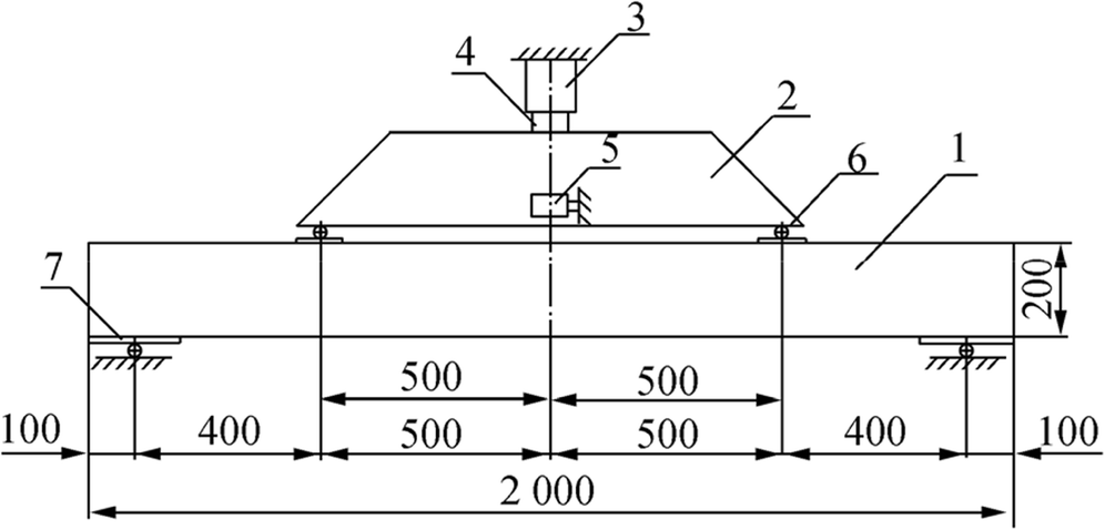 Figure 1 Scheme for the experimental installation. (1) ice beam; (2) distribution beam; (3) hydraulic cylinder; (4) weighing indicator SH-20; (5) sensor of vertical displacements LAS-Z; (6) hinged supports of a distribution beam; (7) hinged supports of the ice beam
The experimental unit has a load frame consisting of columns, racks, upper and lower beams, a loading unit, and a measurement module. The loading unit includes a hydraulic cylinder 4 with a PN of 9 atm and a distribution power beam of 5. The reinforcement from the loading unit is transmitted to the sample 7 through the pivot mounting 6. The loading system is designed so that it provides a pure bending in the mid-span deflection of the ice sample. The vertical displacements of the mid-span cross-section sample are measured using a noncontact laser LAS-Z by Way Con 3 (Germany) mounted on an independent column. The load influenced by the sample is fixed by a LPA-22t weight gauge with a SH-20 weighing indicator from TOKVES (Russian Federation) 2. The loading rate for all samples is 135 kPa/s.
To produce ice specimens with dimensions L × B × H = 2000 mm × 200 mm × 200 mm (L is length, B is width, and H is height), wooden formwork was constructed with 40-mm-thick boards. A 0.03-mm-thick two-layer polyfilm was placed in the formwork. The reinforcing frame was fixed in the formwork, which ensured its location inside the beam, excluding the reinforcement outcropping. Then, the formwork was filled with water. The liquid was exposed to low atmospheric temperatures (t < 0 ℃) until its complete congelation. Due to meteorological conditions, it took 5–7 days to prepare samples at an ambient temperature from 16 to 28 ℃ below zero. Berry et al. (2017) noted a strong effect of temperature below zero on the compressive and tensile properties of fragile materials. Obviously, this factor has a significant impact on the bearing capacity of ice beams.
The total number of experiments carried out was three. For each series, five samples were simultaneously prepared under the same conditions. The experimental data were averaged; the difference between the results did not exceed 15%. The researchers did not study the impact of temperature change on the sample mechanical characteristics.
For the ice beam reinforcement, an all-welded reinforcing frame made of A400 steel reinforcement of a deformed section of 6 mm diameter (Figure 2) was used. A series of preliminary experiments on breaking down the ice samples reinforced by surface reinforcement showed that the most optimal thickness of the protective ice layer is 10 mm, which provided the combined action of ice and reinforcement when loading and the maximum bearing capacity. The temperature pattern inside the beam and heat growth coefficient effect that can weaken a bond between steel and ice have not been studied either.
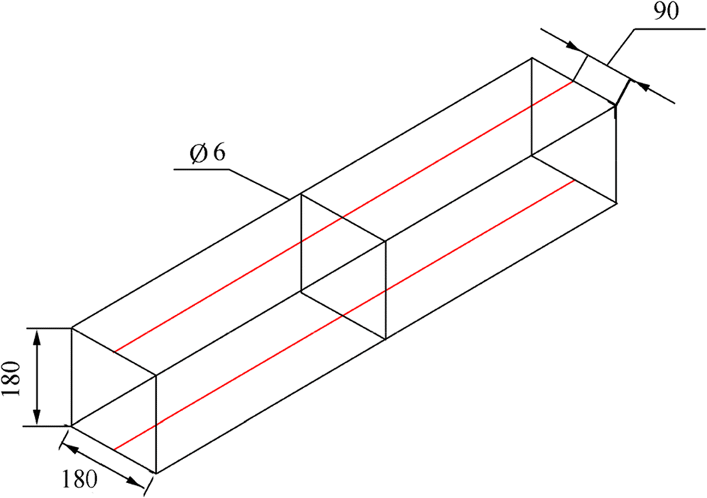 Figure 2 Scheme of the ice beam reinforcement
The experiments on the ice beams were carried out to evaluate the impact of the surface reinforcement of the stretched area strengthened with the reinforcing framework on the carrying capacity of the beams under pure flexure.
2.2 Data on the Numerical Research
Ice is expedient to represent both flexible and fragile materials in numerical research (Yu et al. 2007; Xu et al. 2010). The numerical calculation of the stress–strain state of ice samples was carried out in the ANSYS Workbench software system, with the use of the ANSYS Mechanical module. The model consists of 80 160 finite elements and 89 150 nodes. For ice, nonlinear finite element elements SOLID 65 in the form of a hexahedron were used to simulate elements that allowed cracking in tension and calculations based on Willam and Warnke (1974). User functions applying the deformation criterion of Bazant (Bazant and Cedolin 1980) were introduced to display the cracks.
The finite element BEAM188, which is a beam element with flexural rigidity, was used to simulate the work of the reinforcing materials.
The mechanical characteristics of the materials used to enhance ice in the numerical experiments are presented in Table 1: hot-rolled reinforcement А400 (sample No. 1), reinforcement fiberglass composite (sample No. 2), reinforcement carbon (sample No. 3), reinforcement aramid composite fiber (sample No. 4), and reinforcement combined with a combination of glass and basalt (sample No. 5).
Table 1 Calculated mechanical characteristics of the steel and composite reinforcementParameter name No. 1 No. 2 No. 3 No. 4 No. 5 Maximum tensile stress Ϭbt, n (MPa) 365 168 840 448 320 Compression resistance Ϭbt, n (MPa) 365 63 180 96 96 Modulus of elasticity E (MPa) 20 × 104 50 × 103 130 × 103 70 × 103 10 × 104 On account of the multiplication of the standard characteristics Ϭbt and Ϭbc by the corresponding coefficients, the calculated mechanical characteristics of the used steel and composite reinforcement are shown in Table 1.
3 Results of the Experimental and Numerical Research
The physicomechanical properties of freshwater and sea ice were examined in the works of Qi et al. (2017), Goldstein and Osipenko (2015), Schulson (2015), Tsuchiya et al. (2013), Weiss and Dansereau (2015), and Kim and Keune (2007). A series of preliminary experiments on the loading of unreinforced ice beams were carried out to evaluate the impact of surface reinforcement on the ultimate load carrying capacity of samples. The experiment results determined the beam deflection caused by the load applied to the test sample. The main results of the experiments are shown in Figure 3. Ice had the following mechanical properties (Kozin et al. 2018): E = 700 MPa, uniaxial compression strength Rb = 0.55 MPa, uniaxial tensile strength Rbt = 0.4 MPa, density ρ = 930 kg/m3, and Poisson's ratio μ = 0.3.
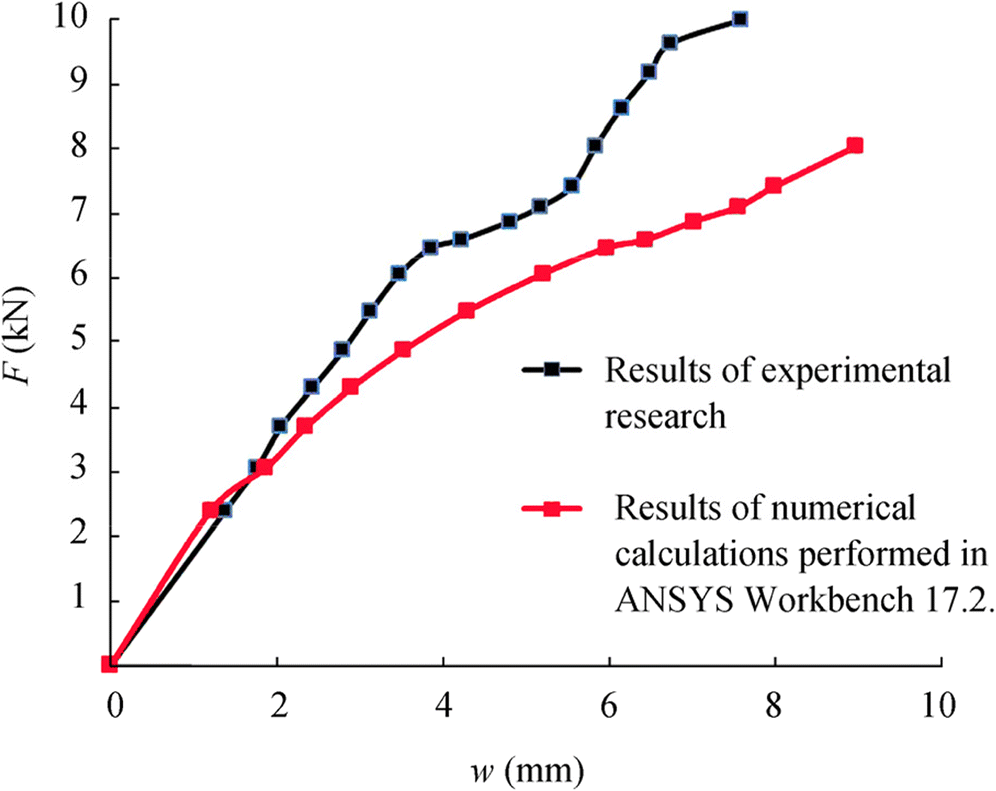 Figure 3 Diagram of the dependence of the deflection of reinforced A400 samples from the load (black line indicates results of the experimental studies; red line indicates results of the numerical calculations performed in ANSYS Workbench 17.2.)
3.1 Comparison of the Experimental and Numerical Research
Figure 3 presents the results of the model experiment with a reinforced A400 sample. The maximum load that the samples sustained in the experiment was approximately 10 kN, which significantly exceeded the maximum load that the unreinforced sample could withstand.
At this condition, the formation of through cracks in the tested samples occurred, and the maximum deflection reached 7.59 mm, after which the complete destruction of the beams occurred.
The outcome analysis of the simulation experiments and numerical calculations allowed the authors to conclude that the experimental values had good agreement in the elastic zone. A rapid growth in the sample strain caused by breaking down most part of its cross section and the loss of bearing capacity was taken as a failure criterion. However, the limit of stretching strain in the reinforcement was not reached. The structural failure occurred during the extensive ice cracking because of the moment of flection in the mid-span of the beam.
3.2 Results of the Numerical Research
An example of calculating the stress–strain state of reinforced sample No. 1 with an A400 reinforcement in the ANSYS Workbench 17.2 software package is shown in Figures 4 and 5.
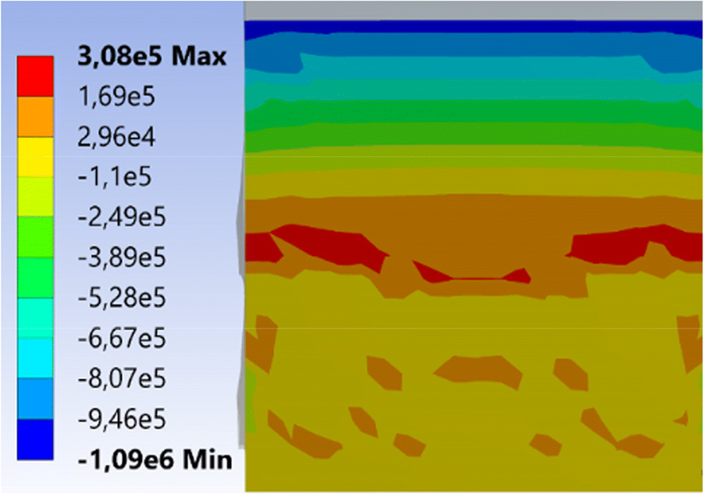 Figure 4 Normal stresses upon failure in median section of the ice beam sample No. 2
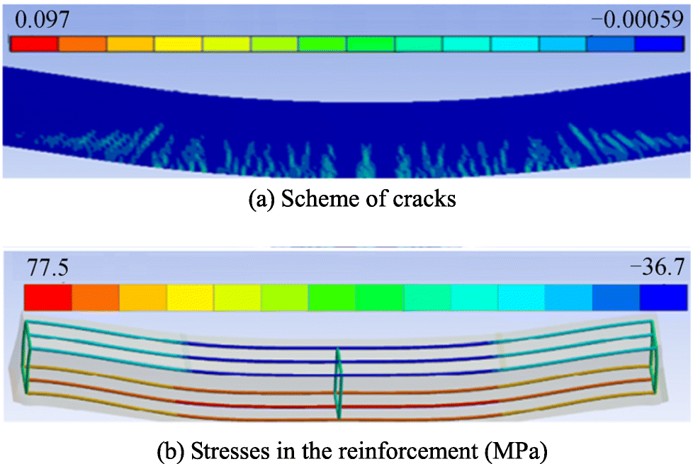 Figure 5 Sample No. 2 during fracture
Figure 4 shows the displacement of the neutral axis of the modeled sample (bottom section tensions are within zero) when the breaking load of approximately 6.88 kN.
The pattern of fractures according to Bazant criterion (Bazant and Cedolin 1980) from − 0.00059 to + 0.097 is shown in Figure 5a. Positive values of the criterion correspond to the occurrence and crack opening in the beam tensile region.
As shown in Figure 5b, the stresses in the reinforcement of the stretched part did not reach the yield point and were approximately 51 MPa.
Figure 6a presents the main findings of the numerical calculations. It illustrates the dependences of the load on the kink for samples reinforced with various materials. Figure 6b and c show the stresses in the middle sections of each reinforced specimens caused by the breaking load for a non-reinforced specimen equal to 3.6 kN.
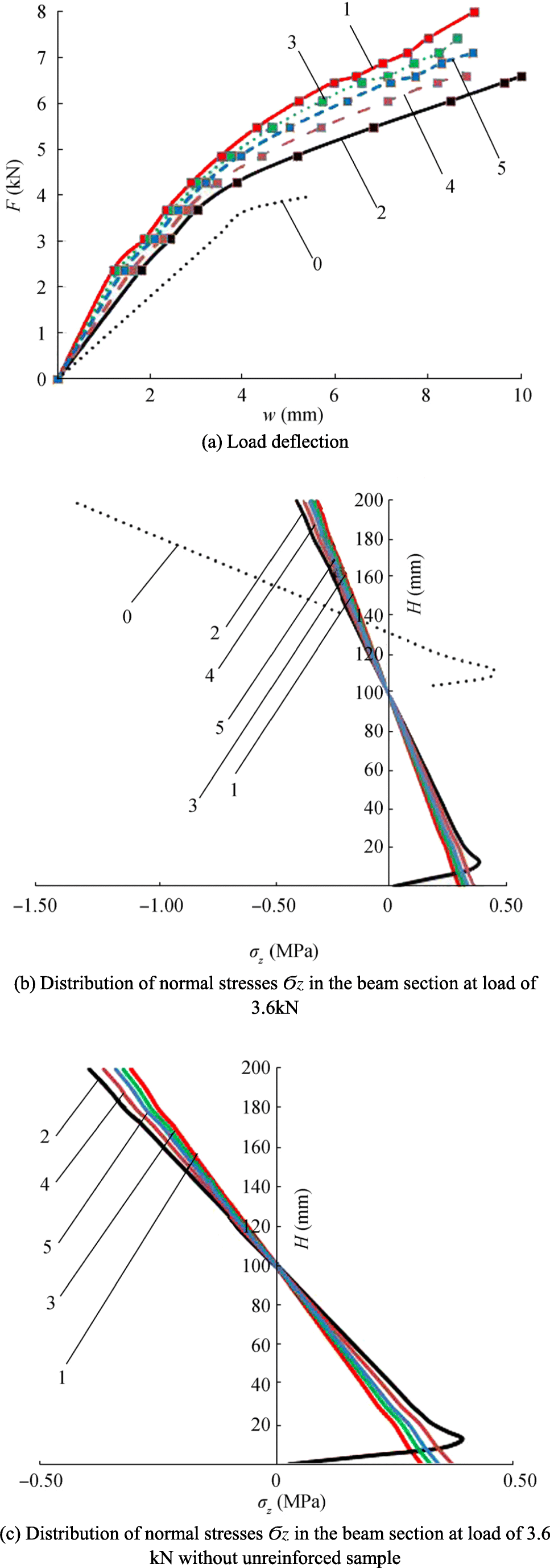 Figure 6 Results of the calculation
The outcome analysis suggests that using reinforced frameworks made of composite materials causes great increase in the load carrying capacity of ice samples. The sample, reinforced with steel reinforcement A400, showed a greater load carrying capacity than the other samples. Samples reinforced with fiberglass and aramid composite reinforcement had the lowest bearing capacity.
The superior limits of stress under a load of 3.6 kN for sample Nos. 1–5 were respectively (in MPa) − 0.30, − 0.39, − 0.32, − 0.37, and − 0.34. The fastest growth of direct stress with increasing load was observed in sample No. 2 and the slowest in sample No. 1.
4 Conclusions
On the basis of the research results, the following conclusions can be drawn:
1) The efficiency validation using medites as reinforcing elements can increase the load carrying capacity of systems in the body of ice. The inclusion of various materials in the ice surface increased its strength by 65%–99% for the focused reinforcement scheme.
2) The breaking down of beam samples in all cases occurred due to extensive ice cracking and moment of flection influence in the mid-span. In this case, the yield stress is not reached in the reinforcement material.
3) The outcomes of the simulation experiments and calculations through the finite element approach agreed well within the elastic zone. The deviations between the compared data did not exceed 20% for sags and breaking strength for the samples reinforced with frameworks made of an A400 steel reinforcement.
-
Figure 1 Scheme for the experimental installation. (1) ice beam; (2) distribution beam; (3) hydraulic cylinder; (4) weighing indicator SH-20; (5) sensor of vertical displacements LAS-Z; (6) hinged supports of a distribution beam; (7) hinged supports of the ice beam
Figure 2 Scheme of the ice beam reinforcement
Figure 3 Diagram of the dependence of the deflection of reinforced A400 samples from the load (black line indicates results of the experimental studies; red line indicates results of the numerical calculations performed in ANSYS Workbench 17.2.)
Figure 4 Normal stresses upon failure in median section of the ice beam sample No. 2
Figure 5 Sample No. 2 during fracture
Figure 6 Results of the calculation
Table 1 Calculated mechanical characteristics of the steel and composite reinforcement
Parameter name No. 1 No. 2 No. 3 No. 4 No. 5 Maximum tensile stress Ϭbt, n (MPa) 365 168 840 448 320 Compression resistance Ϭbt, n (MPa) 365 63 180 96 96 Modulus of elasticity E (MPa) 20 × 104 50 × 103 130 × 103 70 × 103 10 × 104 -
Bazant ZP, Cedolin L (1980) Fracture mechanics of reinforced concrete. J Eng Mech: 1287–1306 Berry M, Johnson J, McDevitt K (2017) Effect of cold temperatures on the behavior and ultimate capacity of GFRP-reinforced concrete beams. Cold Reg Sci Technol 136: 9–16. https://doi.org/10.1016/j.coldregions.2017.01.003" Bychkovsky NN, Guryanov YA (2005) Ice construction sites, roads and ferries. Saratov State Technical University, Saratov, pp 7–38 (in Russian) Goldstein RV, Osipenko NM (2015) Some aspects of strength in sea ice mechanics. Phys Mesomech 18(2): 139–148. https://doi.org/10.1134/S102995991502006X Kim H, Keune JN (2007) Compressive strength of ice at impact strain rates. J Mater 42(8): 2802–2806 https://doi.org/10.1007/s10853-006-1376-x Kostenko AV, Serdecny AS, Serdecny AA (2005) Ice crossing. Patent for the Invention of the Russian Federation, State Educational Institution of Higher Professional Education, Komsomolsk-on-Amur State Technical University, Komsomolsk-on-Amur, No. 2260648. (in Russian) Kozin VM, Kustov AN, Morozov VS (2003) Method for creating an ice crossing. Patent for Invention of the Russian Federation, Komsomolsk-on-Amur State Technical University, Komsomolsk-on-Amur, No. 2198355. (in Russian) Kozin VM, Vidyakin AV, Popenko NV (2011). Method for creating an ice crossing. Patent for Invention of the Russian Federation, Komsomolsk-on-Amur State Technical University, Komsomolsk-on-Amur, No. 2431012. (in Russian) Kozin VM, Zemlyak VL, Vasilyev AS, Ipatov K I (2018). The research of the stressed strain state of ice beams reinforced by surface reinforcement. 2018 ISOPE, Sapporo, 1511–1515 Kozin VM, Vasilev AS, Zemlyak VL, Ipatov KI (2019) Investigation of the limit state of ice cover under conditions of pure bending when using reinforcing elements. Vestnik Tomskogo Gosudarstvennogo Universiteta, Matematika i Mekhanika 61: 61–69 Lu WJ, Lubbad R, Loset S (2015) Out-of-plane failure of an ice floe: radial-crack-initiation-controlled fracture. Cold Reg Sci Technol 119: 183–203. https://doi.org/10.1016/j.coldregions.2015.08.009 Nikitin PE, Nikitina MP (2015). The way of creating a reinforced ice crossing for wide reservoirs. Patent for Invention of the Russian Federation No. 2569694. (in Russian) Qi CF, Lian JJ, Ouyang QN, Zhao X (2017) Dynamic compressive strength and failure of natural lake ice under moderate strain rates at near melting point temperature. Latin Am J Solids Struct 14(9): 1669–1694. https://doi.org/10.1590/1679-78253907 Renshaw CE, Schulson EM, Sigward SJG (2017) Experimental observation of the onset of fracture percolation in columnar ice. Geophys Res Lett 44(4): 1795–1802. https://doi.org/10.1002/2016GL071919 Schulson EM (2015) Low-speed friction and brittle compressive failure of ice: fundamental processes in ice mechanics. Int Mater Rev 60(8): 451–478. https://doi.org/10.1179/1743280415Y.0000000010 Sirotyuk VV, Yakimenko OV, Levashov GM, Zakharenko AA (2016) Reinforcement of ice cover with geosynthetics materials. Earth's Cryosphere 20(3): 86–94 Tippmann JD, Kim H, Rhymer JD (2013) Experimentally validated strain rate dependent material model for spherical ice impact simulation. Int J Impact Eng 57: 43–54. https://doi.org/10.1016/j.ijimpeng.2013.01.013 Tsuchiya R, Muramoto Y, Shimizu N (2013). AC breakdown properties of ice-alcohol mixed system. 2013 ICSD, Bologna, ITALY, 533–536 Weiss J, Dansereau V (2015) Linking scales in sea ice mechanics. Philos Trans Royal Soc A Math Phys Eng Sci 375(2086): 20150352. https://doi.org/10.1098/rsta.2015.0352 Willam KJ, Warnke KJ (1974). Constitutive model for the triaxial behavior of concrete, 1974 Seminar of Concrete Structures Subjected to Triaxial Stresses, Bergamo, 3-11. Xu X, Wei C, Li J (2010). Static ice load for wide cap of sea-crossing bridge. 2010 MACE, Wuhan, 4494-4497. Yakimenko OV, Sirotyuk VV (2014) Reinforcement of ice crossings. Earth's Cryosphere 18(1): 88–91 Yakimenko OV, Sirotyuk VV (2015). Strengthening of ice crossings by geosynthetic materials. SibADI, Omsk, 12-17 (in Russian) Yu B, Wu W, Xu N, Yue Q, Liu S (2007). Numerical simulation of dynamic ice force on conical structure. 2007 POAC, Dalian, 277–285 Zemlyak VL, Kozin VM, Vasilyev AS, Ipatov KI (2019) Experimental and numerical investigations of the influence of reinforcement on the load-carrying capacity of ice crossings. Soil Mech Foundation Eng 56: 37–43