Challenges Associated with the Bypass Valves of Control Valves in a Seawater Service
https://doi.org/10.1007/s11804-020-00132-8
-
Abstract
Modern processing plants use a variety of control loop networks to deliver a finished product to the market. Such control loops, like control valves, are designed to keep process variables such as pressure, temperature, speed, flow, etc. within the appropriate operating range and to ensure a quality product is produced. All control valves have a bypass so that production can proceed if maintenance is needed for the control valve as part of the control loop. The important point is that in both operation and maintenance situations, the bypass valve and the control valve should have approximately the same flow capacity to provide nearly the same amount of pressure. This paper presents a case study in seawater service on the selection of manual bypass valves for a 16″ control valve in class 150 and titanium material. A 16″ butterfly valve of class 150 was chosen for the control valve bypass, which provided a much higher flow capacity than the control valve. In this paper, four solutions are recommended to achieve the same coefficient value (Cv) for the control and bypass valve. Using the reduced size butterfly valve could be the cheapest and best solution. On the other hand, selecting the same control valve for bypass line is the most expensive but maybe the most reliable solution. Using a flow orifice for throttling could be ranked as the second expensive option and the second reliable one. Selection of butterfly valve for throttling is the second cheapest option, but it has the least reliability. Different parameters such as space and weight saving, cost as well as reliability have been considered in evaluation of different solutions.-
Keywords:
- Control valve ·
- Bypass valve ·
- Flow capacity ·
- Restriction orifice ·
- Offshore ·
- Oil and gas
Article Highlights• Modern processing plants use many networks of control loops to produce and deliver a product to the market.• The bypass of a control valve should have almost the same flow capacity as the control valve to avoid process problems.• There are several ways to solve the high flow capacity from the bypass of the control valve such as reducing the size of the bypass valve, using flow orifice after the bypass valve, choosing a globe valve for bypass valve, etc.• Too high flow passing through the bypass valve can jeopardize the process system and increase the bypass valve internals, resulting in wearing and cavitation. -
1 Introduction
A control valve is a type of instrument valve that is chosen to regulate the fluid flow by changing the size of the fluid passage, to control the process variable as close to the desired set point as possible (Sotoodeh 2018a). In general, a control valve controls the process of essential variables such as pressure, temperature, and the liquid level through fluid flow rate control. There are many aspects that are associated with control valve design such as noise (Sotoodeh 2019b), erosion and cavitation (Sotoodeh 2016), metallurgy, fluid mechanics, and actuation. In fact, a control valve is the most common control component in process control and oil and gas industry. The flow characteristic of the control valves is different depending on the closure member shapes. The control valve assembly typically consist of valve body, internal trim parts, an actuator to provide valve movement, and additional valve accessories such as limit switches, transducers, etc. (Fisher and Emerson Automation Solutions 2017). In a simple language, control valve is a type of globe valve in most of the cases supplied with an actuator (automatic operated) which works with pneumatic, electricity, or hydraulic (Nesbitt 2007; Sotoodeh 2019a). The performance of the control valve is largely dependent on the actuators (Sotoodeh 2019a).
A control loop is the combination of blocks which are gathered together to illustrate the control system as a whole. In control loops, deviations are obtained from the desired product quality, and the process variable is modified to achieve this. To prevent the effect of process variations on the target setpoint, sensors capture process variable information and transmitters relay the information to the controller (e.g., control room). To return the process variable to the desired level, a controller processes the information and determines what actions to take (Fisher and Emerson Automation Solutions 2017). The control valve is the most common final control element in process control (Fisher and Emerson Automation Solutions 2017).
2 Arrangement of the Control Valve
An offshore oil and gas plant contains many control loops in order to guarantee the product with the required quality. Figure 1 illustrates a typical control loop system for a control valve. A control valve (Figure 2) is an element in the control system which is in contact with fluid service during the operation with no maintenance possibility without fluid stop (Sotoodeh 2018a). That is why, as shown in Figure 3, the control valve is isolated by two isolation valves (Instrument Society of America 1998). The isolation valves, located on both sides of the control valve, are usually open but closed in case of maintenance of the control valve. Usually, a bypass line including a black bypass valve is installed to provide continuous operation, when the control valve is routinely maintained (Instrument Society of America 1998).
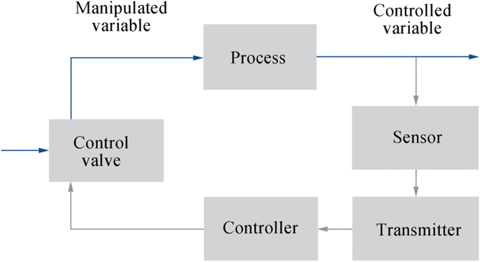 Figure 1 A control loop
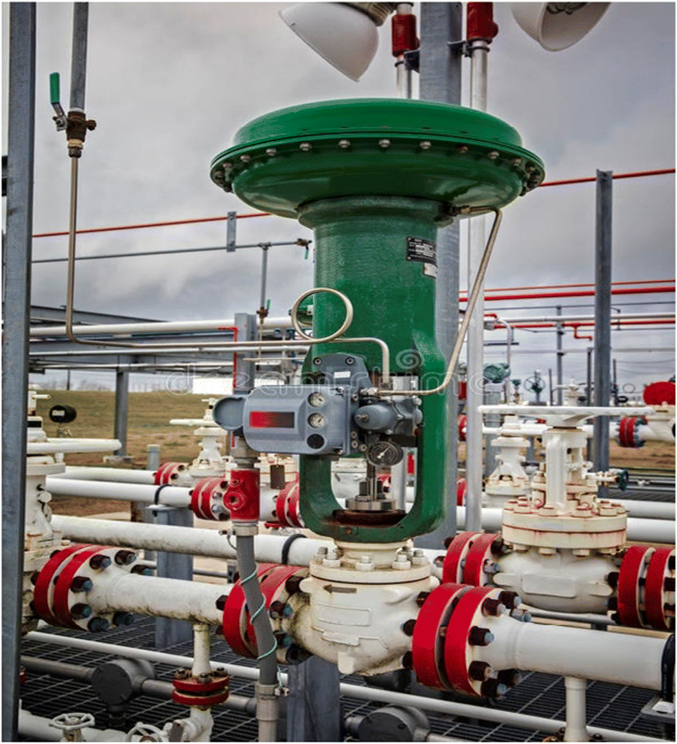 Figure 2 A control valve. Courtesy: Valve Magazine
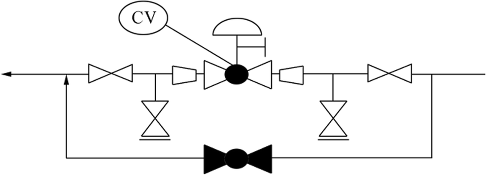 Figure 3 Control valve and bypass line arrangement. Courtesy: Valve Magazine
The next section of this paper is about valve flow capacity expressed in the coefficient value (Cv) or flow coefficient term. If the bypass valve’s flow capacity or Cv is too high compared with the control valve, the bypass valve and the internal valves become too small, and the processing system may be lacking additional fluid flow (Skousen 2011). On the other side, if the bypass valve’s flow capacity is too high, this could result in a higher pressure drop resulting in internal valve wear and cavitation (Skousen 2011).
3 Flow Capacity of the Valve
The opening area of the valve can be adjusted to allow various fluid passage values. The friction loss across the valve varies with the flow, based on Eqs. (1) and (2) (Smit and Zappe 2004):
$$ V\propto {\left(\Delta h\right)}^{1/2} $$ (1) $$ V\propto {\left(\Delta p\right)}^{1/2} $$ (2) where V is flow velocity, ∆h head loss, and ∆p pressure loss. Several relationships and equations between flow capacity and pressure drop have been established for different valve positions. The flow coefficient Cv is the most common (Smit and Zappe 2004). Valve manufacturers provide the Cv data on the general arrangement drawings of the valve. One Cv is defined as one US gallon (1 US gallon = 3.78 L) of 60 °F (16 °C) water flowing through a valve opening (completely opened valve) in 1 min with a pressure drop of 1 psi (0.1 bar). The Cv is calculated using Eq. (3) (Nesbitt 2007):
$$ {C}_v=Q\sqrt{\frac{\mathrm{SG}}{\Delta P}} $$ (3) where Cv is valve flow coefficient, Q flow rate (US gallon/min), SG specific gravity of the fluid, and ∆P the pressure drop (psi).
Figure 4 illustrates valve flow capacity (Q), pressure drop across the valve (∆P), and Cv of a valve. Specific gravity is defined as the density of a fluid compared with the density of water. It is calculated using Eq. (4) (Nesbitt 2007):
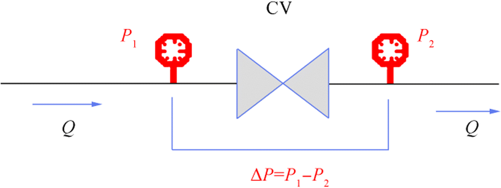 Figure 4 Flow capacity, pressure drop, and Cv across a valve
$$ \mathrm{Specific}\ \mathrm{Gravity}=\frac{\mathrm{Density}\ \mathrm{of}\ \mathrm{a}\ \mathrm{fluid}}{\mathrm{Density}\ \mathrm{of}\ \mathrm{water}}=\frac{\rho_{\mathrm{Fluid}}\ }{\rho_{\mathrm{Water}}} $$ (4) The metric unit of flow coefficient that defines the flow rate passing through a valve is known as Kv-value. One Kv-value is defined as 1 cubic meter of 60 °F (16 °C) water flowing through the opening of a valve (fully opened valve) in 1 h with a pressure drop of 1 bar. The kv-value is calculated using Eq. (5) (Nesbitt 2007):
$$ {K}_v=Q\sqrt{\frac{\rho }{\Delta P}} $$ (5) where Kv is the metric flow coefficient, Q flow rate (m3/h), ρ fluid density (kg/dm3), and ∆P the pressure drop (bar).
The relationships between Cv and Kv are given in Eqs. (6) and (7):
$$ {k}_v=0.865\times {C}_v $$ (6) $$ {C}_v=1.156\times {K}_v $$ (7) Each valve has a flow characteristic showing the relationship between the Cv or flows through the valve and the valve opening percentage (Smit and Zappe 2004). The flow characteristic allows a certain amount of fluid to pass through the valve at a certain percentage of the valve when the valve opens (Smit and Zappe 2004; Nesbitt 2007). The three most common types of flow characteristics are equal percentage, linear, and quick opening. The characteristic of the quick opening is related to the applications where the maximum flow is immediately produced as the valve begins to open. The characteristic of linear flow produces equal flow change per unit of valve stroke (Smit and Zappe 2004). The mathematical formulas of the linear flow characteristic are given in Eqs. (8) and (9):
$$ Q=K\times L $$ (8) $$ \frac{\mathrm{d}Q}{\mathrm{d}L}=K\kern2.5em $$ (9) where Q is flow rate, L valve travel, and K the constant of proportionality.
Equal percentage flow characteristic is very common for throttling valves, which are used for regulating the flow. At the beginning of the valve opening, the amount of flow passing through the valve is minimal in equal percentage.
In the first half of the valve stroke, this provides enhanced range efficiency and flow control (Smith and Zappe, 2004). The mechanical formulas for equal percentage characteristics are given in Eqs. (10) and (11):
$$ Q={Q}_0{e}^{nl} $$ (10) $$ \frac{\mathrm{d}Q}{\mathrm{d}L}= nQ\kern1em $$ (11) where Q the flow rate, L valve travel, e the 2.718, Q0 minimum controllable flow, and n is constant.
Figure 5 illustrates the three flow curves based on the valve opening percentage.
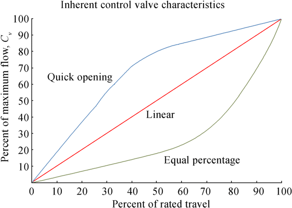 Figure 5 Valve flow curve based on travel percentage
4 Case Study
A 16″ (globe type) control valve in class 150 and titanium material handles seawater service with a Cv of 1650 gal/min. The control valve with the 50PV0060 tag number is responsive to pressure change and is used with the same percentage flow characteristic for pressure control applications. The line on which the control valve is situated should have an operating pressure of 4.9 bar. Any high or low deviation from the 4.9 bar set pressure provides a signal to the valve actuator from the pressure control loop (50PT0060). The signal triggers the movement of the control valve Closure member to increase or decrease the amount of flow to reach the required 4.9 bar pressure. Figure 6 demonstrates the arrangement of the control valve in the case study (Smit and Zappe 2004).
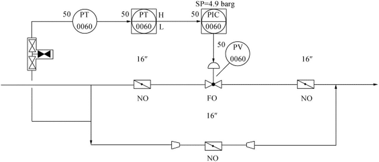 Figure 6 General arrangement of the control valve 50PV0060
The control valve is isolated in seawater service with two normally open (NO) butterfly valves of the wafer form instead of ball valves. For isolation purposes, butterfly valves of the wafer type are selected because they are lighter, more compact, and cheaper, with low torque operating requirements (Sotoodeh 2018b, 2018c). Since this valve is cheaper and more compact than the globe valve, the control valve bypass is also selected instead of a globe valve as a butterfly valve style wafer (Sotoodeh 2018c).
A 16″ CL 150 butterfly valve was selected for the bypass line initially. The flow curve of the valve has been reviewed, and as shown in flow curve, the Kv-value of 16″ and a 100% open butterfly valve (90 °C opening angle) is 7000 m3/h. The Cv of the butterfly valve can be calculated using Eq. (7):
$$ {C}_v=1.156\times {K}_v=1.156\times 7000=8092\ \mathrm{gal}/\min $$ The Cv of the 16″ class 150 butterfly valve is about five times higher than the control valve. Excessive flows through the bypass valve will jeopardize the processing system and increase the internal bypass valve, leading to wear and cavitation. To solve this problem, many solutions are proposed as follows (Sotoodeh 2018a ).
1) Reduce the size of the butterfly valve: the Cv value of an 8″ class 150 wafer type butterfly valve is 1502.8 gal/min. This value is similar to the control valve Cv. The first solution, therefore, is to replace the butterfly valve type of the 16″ class 150 wafer type to an 8″ with the same pressure class.
2) Choose a globe valve for the bypass line: a globe valve should have Cv very similar to that of the control valve in the same size and pressure class since they are the same. Changing the butterfly valve of the wafer type to a globe valve, however, will increase costs, weight, and volume. Table 1 provides Cv values for the various sizes of a class 150 globe valve. For the bypass of the control valve with a Cv value of 1521, a 16″ globe valve should be selected based on the data presented in Table 1.
Table 1 Cv of class 150 globe valves for 10″ to 18″ size rangesSize (inch) Cv (gal/min) 10″ 715 12″ 1184 14″ 1198 16″ 1606 18″ 1724 3) Use the butterfly valve 16″ class150 for throttling: the 16″ butterfly valve can be opened to some degree to get a 1650 gal/min Cv. A disk opening angle of 40° produces a Cv near the control valve. Because a disk opening angle of 90° offers 100% opening, an opening angle of 40° means only 44.4% opening. This solution may not be feasible unless the operator remembers to open the valve up to 44.4%, and the butterfly valve should be equipped with a position indicator to display the disk status, as shown in Figure 7.
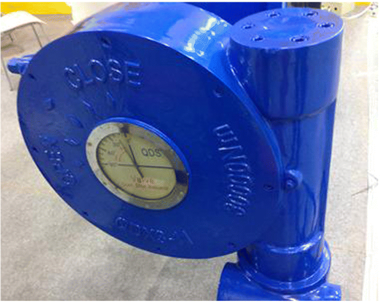 Figure 7 Position indicator on butterfly
4) Use a flow orifice to reduce the flow rate: install a flow orifice or restriction orifice (Figure 8) downstream of the bypass 16″ butterfly valve to reduce the flow rate after the bypass valve. An orifice plate (restriction orifice) restricts the fluid flow and the downward pressure from the upstream to the downstream (Nayyar 2000; Parisher and Rhea 2002). The restriction orifice should be properly designed to provide the required flow rate and pressure drop in compliance with the ISO 5167 (2003) standard. It is not part of this paper to size the restriction orifice.
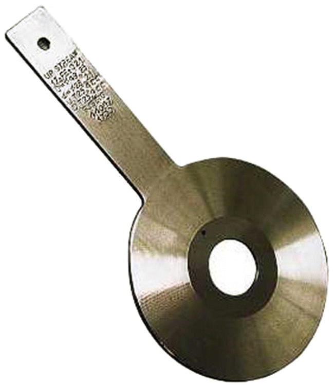 Figure 8 Restriction orifice
The restriction orifice should, however, provide the same flow through the control valve. The flow capacity from the control valve can be calculated using Eq. (3).
1650 = Q$ \sqrt{\frac{1.02}{1}} $ → Q = 1634 gal/min × 0.00378541 m3/gal = 6.1853 m3/min × 60 min/h = 371.118 m3/h × 1018 kg/m3= 377 798.124 kg/h.
The density of seawater is 1018 kg/m3, so it is possible to calculate the specific gravity of the water using Eq. (4).
$$ \mathrm{Specific}\ \mathrm{gravity}=\frac{\mathrm{Density}\ \mathrm{of}\ \mathrm{the}\ \mathrm{fluid}}{\mathrm{Density}\ \mathrm{of}\ \mathrm{the}\ \mathrm{water}}=\frac{\rho_{\mathrm{Fluid}}\ }{\rho_{\mathrm{Water}}}=1018/1000=1.02 $$ Table 2 summarizes proposed solutions and provides ranking for them based on reliability as well as size and cost evaluations.
Table 2 Ranking and summarizing the proposed solutionsProposals Size, weight, and cost reduction ranking Reliability ranking Reduce the size of butterfly valve 1st 3th Choose a globe valve for bypass line 4th 1st Using butterfly valve for throttling 2nd 4th Using orifice plate 3rd 2nd 5 Conclusions
This paper provides a case study on the selection of bypass manual valves for a 16″ control valve in class 150 and titanium material in seawater service. For the bypass of the control valve, a 16″ butterfly valve of class 150 was selected, which provided much higher flow capacity compared with the control valve. To avoid process problems, the bypass of a control valve should have nearly the same flow capacity as the control valve. However, the same size and type of control valve are not necessarily the same as the bypass valve. Also, it is found that an 8″ butterfly valve can be used as a bypass valve for a 16″ globe control valve. Lastly, four solutions for achieving the same Cv for the control and the bypass valve were recommended in this study. Using the reduced size butterfly valve could be the cheapest and best solution. On the other hand, selecting the same control valve for bypass line is the most expensive but maybe the most reliable solution. Using a flow orifice for throttling could be ranked as the second expensive option and the second reliable one. Selection of butterfly valve for throttling is the second cheapest option, but it has the least reliability. Considering different parameters such as size and weight saving, cost, and reliability, all the proposed options have been summarized. The most reliable and expensive solution is to select a globe valve for bypass line, and the less expensive solution is to reduce the size of butterfly valve on the bypass.
Acknowledgments: I would like to express my gratitude to my partner, Ms. Tamara Zhunussova, for her great support. -
Figure 1 A control loop
Figure 2 A control valve. Courtesy: Valve Magazine
Figure 3 Control valve and bypass line arrangement. Courtesy: Valve Magazine
Figure 4 Flow capacity, pressure drop, and Cv across a valve
Figure 5 Valve flow curve based on travel percentage
Figure 6 General arrangement of the control valve 50PV0060
Figure 7 Position indicator on butterfly
Figure 8 Restriction orifice
Table 1 Cv of class 150 globe valves for 10″ to 18″ size ranges
Size (inch) Cv (gal/min) 10″ 715 12″ 1184 14″ 1198 16″ 1606 18″ 1724 Table 2 Ranking and summarizing the proposed solutions
Proposals Size, weight, and cost reduction ranking Reliability ranking Reduce the size of butterfly valve 1st 3th Choose a globe valve for bypass line 4th 1st Using butterfly valve for throttling 2nd 4th Using orifice plate 3rd 2nd -
Fisher & Emerson Automation Solutions (2017) Control valve handbook, 5th ed. York, New Instrument Society of America (1998). Control valve features: evaluating the need for bypass and block valves. Available from: https://www.globalspec.com/reference/13638/179909/chapter-10-23-control-valve-features-evaluating-the-need-for-bypass-and-block-valves International Organization for Organization (2003). Measurement of fluid flow by means of pressure differential devices inserted in circular conduits running full. ISO 5167, 2nd edition, Geneva, 1–20 Nayyar ML (2000) Piping handbook, 7th ed. McGraw-Hill Education, New York, pp 25–150 Nesbitt B (2007) Handbook of valves and actuators: valves manual international, 1st ed. Elsevier, Oxford Parisher RA, Rhea RA (2002). Pipe drafting and design. 2nd ed., Gulf Professional Publishing, 112-152 Skousen PL (2011) Valve handbook, 3rd ed. McGraw-Hill Education, New York, pp 10–95 Smit P, Zappe RW (2004) Valve selection handbook, 5th ed. Elsevier, New York, pp 20–120 Sotoodeh K (2016) Cavitation in globe valves and solutions. Valve World Magazine 21(3):32–36 Sotoodeh K (2018a). Valve selection for bypass of control valves: A case study. Available from: http://www.valvemagazine.com/web-only/categories/technical-topics/9454-valve-selection-for-bypass-of-control-valves-a-case-study.html [Accessed on Jan. 23, 2019] Sotoodeh K (2018b) Why are butterfly valves a good alternative to ball valves for utility services in the offshore industry? Am J Ind Eng 5(1):36–40. https://doi.org/10.12691/ajie-5-1-6 Sotoodeh K (2018c) Selecting a butterfly valve instead of a globe valve for fluid control in a utility service in the offshore industry (based on an industrial experience). Am J Mech Eng 6(1):27–31. https://doi.org/10.12691/ajme-6-1-4 Sotoodeh K (2019a). Actuator selection and sizing for valves. Springer nature applied science, Vol. 1, article No. 1207(2019). https://doi.org/10.1007/s42452-019-1248-z Sotoodeh K (2019b) Noise and acoustic fatigue analysis in valves case study of noise analysis and reduction for a 12″ x 10″ pressure safety valve. J Fail Anal Prev 19(3):838–843. https://doi.org/10.1007/s11668-019-00665-3