Active Control of Sound Transmission in Ship Cabins Through Multiple Independently Supported Flexible Subplates
https://doi.org/10.1007/s11804-020-00123-9
-
Abstract
The vibration and noise produced by the powertrain and waves inside ship cabins limit working efficiency and crew and passengers' accommodation quality. This paper simplifies ship cabins as cavities and explores active control techniques to attenuate sound transmission via multiple parallel-supported flexible subplates. The theoretical formulations of the interaction between multiple subplates and cavities were performed and the coupling relationships between them were analyzed. Based on the multiple subplates and the cavity coupling models, numerical simulations were performed using the derived optimal controller to minimize the transmission of sound into the cavities through two and nine parallel-supported subplates. The various control strategies were explored to minimize the coupling system's acoustic potential energy, and the control performances were compared and discussed. The mechanism of reducing sound transmission through multiple supported subplates into a cavity is revealed. The simulation results showed that the vibration pattern of the controlled subplate is changed after it is regulated, which increases its radiation to subdue the other subplates' radiation, while increasing vibration of the controlled subplate. The more subplates a cavity has, the more kinetic energy the controlled subplate possess. Furthermore, the noise reduction performance of a cavity with fewer subplates is better than that with more subplates.Article Highlights• The theoretical formulations of sound transmission through multiple subplates into cavities were performed and various control strategies were explored.• The noise attenuation results of active control systems are related to the number of subplates of a cavity.• The simulation results showed that the vibration pattern of the controlled subplate is changed by increasing its radiation to subdue the other subplates' radiation after control. -
1 Introduction
Noise pollution has been acknowledged as a serious issue for our safety, and the design of quiet systems has become one of the major concerns which have attracted a great deal of interest in ship cabin engineering (Ankit 2018; Kletschkowski 2012; Wszołek 2017). In many applications, an enclosure's interior noise is caused by external sound sources that transmit to the cavity through flexible plates such as rail carriages (Sadri and Younesian 2015), offices, and automobiles (Du and Zhang 2012). The noises generated by diesel, generator, and waves are more extreme for ship cabins, which dramatically reduces crew and passengers' work performance and comfort (Amromin 2018; Cheer and Elliott 2016; Kandouci and Adjal 2014). Fatigue and comfort for crew and passengers were given more priority during the design of modern ships (Kurt et al. 2016). The noise control of ships becomes an important subject in such a background (Naveen et al. 2014; Borelli et al. 2016; Zhang 2017). To make it easy to analyze the acoustics inside a ship cabin, it is usually simplified as a structural-acoustic coupling cavity, which has been investigated by many researchers. Snyder and Tanaka (1993) analyzed the feedforward control strategies to reduce the interior noise of an enclosure. Noise reduction was analyzed by Pan et al. (1990) and Pan and Hansen (1991) using a force actuator to control noise transmission to a cavity with various noise incident angles. Using both force and acoustic secondary sources, Kim and Brennan (2000) tried to reduce sound transmission into a cavity. Al-Bassyiouni and Balachandran (2005) then used a spherical wave as an incident sound to investigate the interactions between an external and enclosed field of sound. Tanaka and Kobayashi (2006) divided the coupling modes into four categories and handled them separately to effectively reduce the acoustic potential energy. Jin et al. (2009) and Cui and Chen (2012) researched a cavity having two opposite flexible panels and two adjoining flexible panels. The vibroacoustic response of a circular plate backed by a cylindrical enclosure was investigated by Hasheminejad and Shakeri (2017). The finite element method is also used to analyze the coupling mechanism in addition to the analytical method (Wang et al. 2014; Wang et al. 2015). Liang and Yu (2013) analyzed the impact on the cabin acoustic using the finite element of fireproof rock wools with different thicknesses. Xu et al. (2017) used finite element and boundary element methods to predict the ship cabin's sound response.
Most of the previous research, however, focused on coupling systems with one flexible plate on one side. A cavity with one flexible plate, consisting of multiple independently supported subplates, has not been thoroughly investigated, and these types of cavities are very common in ship cabins. For example, some ships cabins have several independently installed glasses, the acoustics inside them is more complicated than the previous analysis. Besides, the previous research optimized the secondary source positions to improve the noise reduction, resulting in a dispersive installation of secondary sources and being difficult to integrate into one control system device in the engineering. In this paper, the theoretical and numerical investigations were performed based on the research of Yang et al. (2017) to analyze the coupling mechanism for a system with multiple independently supported subplates by controlling one subplate each time and implementing closely distributed secondary sources to minimize the transmission of noise.
The rest of the paper is structured as follows: Section 2 introduces theoretical formulations of several self-supported subplate models. The maximum efficacy of the controller is derived from Section 3. Section 4 displays two different model simulations. The findings are presented in Section 5.
2 Analytical Models
In this section, ship cabins are simplified as structural-acoustic coupling cavities and are investigated theoretically. Only the top plate is flexible and the other five plates are acoustically rigid. Assuming that the cavity has dimensions of Lx×Ly ×Lz. The incident sound simultaneously excites the top flexible plate consisting of different subplates. Figure 1 a and b show two different models, which consist of two and nine individually supported subplates, respectively.
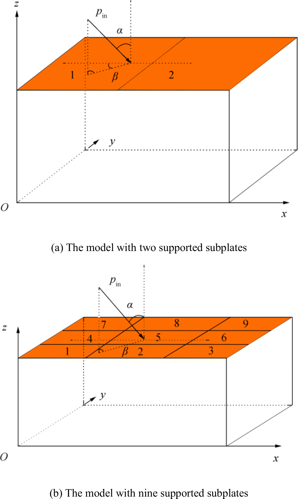 Figure 1 Structural-acoustic coupling models
Generally, assuming the top flexible plate consists of Nχ subplates and each subplate has the same size of (Lx/Tx)×(Ly/Ty), that is Nχ = Tx×Ty. The subplates are excited by an external sound pext, interior sound p, and Nf forces fi from a control system simultaneously. Then, vibration of undamped subplate χ can be expressed as given in Eq. (1) (Hansen et al. 2012):
$$ \begin{array}{l} L\left[ {{w_\chi }\left( {r,t} \right)} \right] + {\rho _s}{h_s}\frac{{{\partial ^2}{w_\chi }\left( {r,t} \right)}}{{\partial {t^2}}} = \\ \sum _{i = 1}^{{N_f}}{f_{\chi ,i}}(r)\delta \left( {r - {r_i}} \right) + {p_{{\rm{ext}}}}\left( {r,t} \right) - p\left( {r,t} \right),\chi = 1,2, \ldots {N_\chi } \end{array} $$ (1) where L[·], ρs, hs, and wχ(r, t) are the self-adjoint differential operator, the density, thickness, and displacement of the subplate χ; r is the coordinate of interested area of the subplate χ.
If the vibration of subplate χ is expressed using a finite summation of Ns modes as $ {w}_{\chi}\left(r,t\right)={\sum}_{i=1}^{N_s}{w}_{\chi, i}{\psi}_{\chi, i}(r) $ and each mode satisfies $ L\left[{\psi}_{\chi, i}\right]-{\omega}_{s\chi, i}^2{\rho}_s{h}_s{\psi}_{\chi, i}=0 $ (Fahy and Gardonio 2007), the ith structural modal amplitude is derived as:
$$ {w}_{\chi, i}=\frac{\left({\sum}_{j=1}^{N_f}{f}_j\left({r}_j\right){\psi}_{\chi, i}\left({r}_j\right)+{\int}_s\left({p}_{\mathrm{ext}}\left(r,t\right)-p\left(r,t\right)\right){\psi}_{\chi, i}\left(\mathrm{r}\right)\mathrm{d}r\right)}{M_{\chi, i}\left({\omega}_{s\chi, i}^2-{\omega}^2+\mathrm{j}2{\xi}_{s\chi}{\omega \omega}_{s\chi, i}\right)} $$ (2) where ξsχ is the damping of subplate χ, ω is the angular frequency of the incident sound, ψχ, i(r) is the ith structural mode shape function, and ωsχ, i is the ith natural frequency. For a simply supported subplate, its mode shape is defined as ψχ, i(r) = sin (uπ(x − Xχ)/(Lx/Tx)) sin (vπ(y − Yχ)/(Ly/Ty)), χ = 1, ⋯Nf, where Xχ and Yχ are the coordinates of the nearest corner of the subplate χ to the origin in x and y directions, u and v are ith structural modal indices in x and y directions, and Mχ, i = ∫Sρshsψχ, i(r)ψχ, i(r)dr. Since the interior pressure can be expressed as $ p\left({r}_e\right)={\sum}_{j=1}^{N_c}{p}_j{\varphi}_j\left({r}_e\right), $ where mode shape function φj(σ) = cos (lπx/Lx) cos (mπy/Ly) cos (nπz/Lz), l, m, and n are jth acoustic modal indices in x, y, and z directions, the velocity modal amplitudes of the subplate χ can be written in vector form as:
$$ {V}_{\chi }={\boldsymbol{\varLambda}}_{s\chi}\left({\boldsymbol{Z}}_{s\chi}{\boldsymbol{F}}_{\chi }+{\boldsymbol{G}}_{\chi }-{\boldsymbol{B}}_{\chi}^T{\boldsymbol{P}}_{\mathrm{int}}\right) $$ (3) where Λsχis a Ns × Ns diagonal matrix and is defined as $ {\Lambda}_{s\chi}\left(i,i\right)=\mathrm{j}\omega /\left({M}_{\chi i}\left({\omega}_{s\chi, i}^2-{\omega}^2+\mathrm{j}2{\xi}_{s\chi}{\omega \omega}_{s\chi, i}\right)\right) $, Fχ is the control force vector defined as $ {\boldsymbol{F}}_{\chi }=\left[{f}_{\chi, 1};{f}_{\chi, 2};\cdots; {f}_{\chi, {N}_f}\right] $ and the modal amplitudes of incident sound is $ {\boldsymbol{P}}_{\mathrm{int}}=\left[{p}_1;{p}_2;\cdots; {p}_{N_c}\right] $, $ {\boldsymbol{Z}}_{s\chi}=\left[{\psi}_{\chi, 1}\left({r}_1\right),\cdots, {\psi}_{\chi, 1}\left({r}_{N_f}\right),\cdots, {\psi}_{\chi, {N}_s}\left({r}_{N_f}\right)\right] $ denotes the structural impedance matrix input and is derived by substituting the coordinate of the excitation forces with the modal shape function of the subplate χ, $ {\boldsymbol{G}}_{\chi }=\left[{g}_{\chi, 1};{g}_{\chi, 2};\cdots; {g}_{\chi, {N}_s}\right] $ is the modal amplitude vector of the subplate excited by the incident sound, and gχ, i = ∫Spext(r, t)ψχ, i(r)dr. By defining the number coordinates of subplate χ as:
$$ {\displaystyle \begin{array}{c}{\chi}_x={X}_{\chi }/\left({L}_x/{T}_x\right)\\ {}{\chi}_y={Y}_{\chi }/\left({L}_y/{T}_y\right)\end{array}} $$ (4) the generalized modal amplitude with a unit incident sound in τ direction can be obtained as:
$$ {\displaystyle \begin{array}{l}{I}_{n,\tau}\left(u,a\right)={\left(-1\right)}^{u{\chi}_x}{\int}_{na}^{\left(n+1\right)a}\sin \frac{un\tau}{a}{\mathrm{e}}^{-j{k}_{\tau}\tau}\mathrm{d}\tau =\\ {}\left\{\begin{array}{l} ja{\left(-1\right)}^{u{\chi}_x+1}\operatorname{sign}\left({k}_{\tau}\right)/2; k\tau =\pm \mathrm{u}\pi /a\\ {}u\pi a\left(1-{\left(-1\right)}^u{\mathrm{e}}^{-j{k}_{\tau }a}\right){\left(-1\right)}^{\left(n+{\chi}_x\right)u}{\mathrm{e}}^{- jna{k}_{\tau }}/\left({\left(\mathrm{u}\pi \right)}^2-{\left(a{k}_{\tau}\right)}^2\right);\mathrm{others}\end{array}\right.\end{array}} $$ (5) where τ denotes the direction of x or y; a, n, and u are the length, the number coordinate, and the ith structural modal index of subplate χ in τ direction. The j in Eq. (5) is the imaginary unit and without a specific explanation, it denotes a number in other equations. According to the above analysis, the modal amplitude excited by the incident sound can be expressed as:
$$ {g}_{\chi, i}=2{\boldsymbol{P}}_{\mathrm{int}}{\boldsymbol{I}}_{\chi_x,x}\left(u,{L}_x/{T}_x\right){\boldsymbol{I}}_{\chi_y,y}\left(v,{L}_y/{T}_y\right) $$ (6) where u and v are ith structural modal indices in x and y directions.
Bχ(j, i) in Eq. (3) is the coupling matrix between the ith structural mode of subplate χ and jth acoustic mode of the cavity, which is defined as Bχ (j, i) = ∬Sφj(r)ψχ, i(r)dr. By expressing the coupling relation between the ith structural mode of subplate χ and the jth acoustic mode of the cavity in τ direction as:
$$ {\boldsymbol{H}}_{\chi, \tau}\left(u,l\right)={T}_{\tau }{uL}_{\tau}\frac{\cos \left({\chi}_{\tau }l\pi /{T}_{\tau}\right)-{\left(-1\right)}^u\cos \left(\left({\chi}_{\tau }+1\right)l\pi /{T}_{\tau}\right)}{\left({\left({T}_{\tau }u\right)}^2-{l}^2\right)\pi} $$ (7) the following formulation can be derived:
$$ {\boldsymbol{B}}_{\chi}\left(j,i\right)={\left(-1\right)}^n{\boldsymbol{H}}_{\chi, x}\left(u,l\right){\boldsymbol{H}}_{\chi, y}\left(v,m\right) $$ (8) The exact coupling matrix expressions are given in the Appendix for two-subplate and nine-subplate models. In compliance with Eq. (8), each subplate will affect the cavity's acoustic modes independently. Previous research divided the relationship of coupling between structural modes and acoustic modes into four categories, and only the modes in the same categories can be coupled with each other. However, the previous coupling relationships cannot hold in the multiple parallel-supported flexible subplates systems. For example, all structural modes will be coupled with the acoustic modes having an odd index in the x-axis.
The inhomogeneous sound equation inside the cavity is:
$$ {\nabla}^2p\left(\sigma, t\right)-\frac{\partial^2p\left(\sigma, t\right)}{c^2\partial {t}^2}=-{\rho}_0\frac{\partial }{\partial t}\left[{\sum}_{i=1}^{N_q}{q}_i\delta \left(\sigma -{\sigma}_i\right)+{\sum}_{\chi =1}^T\frac{\partial {w}_{\chi}\left(r,t\right)}{\partial t}\right] $$ (9) where Nq is the number of acoustic control sources inside the cavity. Similarly, the mode amplitude of the sound can be written as:
$$ {p}_j=\frac{\mathrm{j}{\omega \rho}_0\left[{\sum}_{i=1}^{N_q}{q}_i{\varphi}_j\left({r}_i\right)+{\Sigma}_X^T{\int}_S{v}_{\chi }(x){\varphi}_j(r)\mathrm{d}r\right]}{A_j\left({k}_{p,j}^2-{k}^2+\mathrm{j}2{\xi}_p{kk}_{p,j}\right)} $$ (10) where $ {A}_j={\iiint}_V{\varphi}_j^2(r)\mathrm{d}r $ and ξp are the damping of the air inside the cavity. The modal amplitudes of the sound can also be written in vector form as:
$$ {\boldsymbol{P}}_{\mathrm{int}}={\boldsymbol{\varLambda}}_c\left({\boldsymbol{Z}}_c\boldsymbol{Q}+{\sum}_{\chi =1}^{N_{\chi }}{\boldsymbol{B}}_{\chi }{\boldsymbol{V}}_{\chi}\right) $$ (11) where Λc is a Nc × Nc diagonal matrix and $ {\boldsymbol{\varLambda}}_c\left(j,j\right)=\mathrm{j}{\omega \rho}_0/\left({A}_j\left({k}_{p,j}^2-{k}^2+\mathrm{j}2{\xi}_p{kk}_{p,j}\right)\right) $, Zc is an input acoustic impedance matrix and is defined as $ {\boldsymbol{Z}}_c=\left[{\varphi}_1\left({\sigma}_1\right),\cdots, {\varphi}_1\left({\sigma}_{N_q}\right),\cdots, {\varphi}_{N_c}\left({\sigma}_{N_q}\right)\right] $, $ \boldsymbol{Q}=\left[{q}_1;{q}_2;\cdots; {q}_{N_q}\right] $ is the acoustic control source strength vector, and Nχ represents the total number of subplates.
By combining Eqs. (3) and (11), the acoustic modal amplitude vector is rewritten as:
$$ {\boldsymbol{P}}_{\mathrm{int}}={\boldsymbol{\varLambda}}_c\frac{{\boldsymbol{Z}}_c\boldsymbol{Q}+{\sum}_{\chi =1}^{N_{\chi }}{\boldsymbol{B}}_{\chi }{\boldsymbol{\varLambda}}_{s\chi}\left({\boldsymbol{Z}}_{s\chi}{\boldsymbol{F}}_{\chi }+{\boldsymbol{G}}_{\chi}\right)}{{\boldsymbol{I}}_{N_c}+{\boldsymbol{\varLambda}}_c{\sum}_{\chi =1}^{N_{\chi }}{\boldsymbol{B}}_{\chi }{\boldsymbol{\varLambda}}_{s\chi}{\boldsymbol{B}}_{\chi}^T} $$ (12) 3 Minimization of Acoustic Potential Energy
It has been proven that the optimal cost function for controlling interior noise is acoustic potential energy, which is defined as $ {E_p}\left( \omega \right) = \iiint {_V|p\left( {r,\omega } \right)2/\left( {4{\rho _0}c_0^2} \right){\rm{d}}r} $ and can be rewritten as (Nelson et al. 1987):
$$ {E}_p={\boldsymbol{P}}_{\mathrm{int}}^{\mathrm{H}}{\boldsymbol{\varLambda} \boldsymbol{P}}_{\mathrm{int}} $$ (13) where Λ is a diagonal matrix and $ \boldsymbol{\varLambda} \left(i,i\right)={A}_i/\left(4{\rho}_0{c}_0^2\right) $. By substituting Eq. (12) into Eq. (13), we can derive the following formulation:
$$ {E}_p={\left(\boldsymbol{TC}+\boldsymbol{XG}\right)}^{\mathrm{H}}{\boldsymbol{Z}}^{\mathrm{H}}\boldsymbol{\varLambda} \boldsymbol{Z}\left(\boldsymbol{TC}+\boldsymbol{XG}\right) $$ (14) where $ \boldsymbol{G}=\left[{G}_1;\cdots; {G}_{N_{\chi }}\right] $, $ \boldsymbol{Z}={\boldsymbol{\varLambda}}_c/\left({\boldsymbol{I}}_{N_c}+{\boldsymbol{\varLambda}}_c{\sum}_{\chi =1}^{N_{\chi }}{\boldsymbol{B}}_{\chi }{\boldsymbol{\varLambda}}_{s\chi}{\boldsymbol{B}}_{\chi}^{\mathrm{T}}\right) $, T = [BχΛSχZSχ, Zcχ], and $ \boldsymbol{C}=\left[{\boldsymbol{F}}_{N_{\chi }};\boldsymbol{Q}\right] $, χ denotes the subplate of being controlled, $ \boldsymbol{X}=\left[{\boldsymbol{B}}_1{\boldsymbol{\varLambda}}_{S1},\cdots, {\boldsymbol{B}}_{N_{\chi }}{\boldsymbol{\varLambda}}_{SN_{\chi }}\right] $. By minimizing Eq. (14), the optimal output of the controller is derived as:
$$ \boldsymbol{C}=-{\left({\boldsymbol{T}}^{\mathrm{H}}{\boldsymbol{Z}}^{\mathrm{H}}\boldsymbol{\varLambda} \boldsymbol{ZT}\right)}^{-1}{\boldsymbol{T}}^{\mathrm{H}}{\boldsymbol{Z}}^{\mathrm{H}}\boldsymbol{\varLambda} \boldsymbol{ZXG} $$ (15) 4 Simulation Results and Discussion
This section presents the results of the control mechanisms of the investigated multiple subplates and cavity coupling models, including the various control configurations, explored. All the following simulations were conducted based on the cabin coupling relationship and subplates analyzed using MATLAB in Sections 2 and 3. The models used here are a two-subplate model (cavity 1) shown in Figure 1a and a nine-subplate model (cavity 2) shown in Figure 1b. The basic parameters of the two cavities and incident angle (α, β) of unit noise are listed in Tables 1 and 2. The dimensions of two cavities are 2.34 m (Lx) ×0.9 m (Ly)×1.5 m (Lz) and 3.51 m (Lx)×2.7 m (Ly) ×1.5 m (Lz), respectively. The first ten modal frequencies of the subplate and two cavities are listed in Table 3.
Table 1 Properties of subplatesYoung's modulus (GPa) Thickness (mm) Density (kg/m3) 60 5 2400 Table 2 Properties of the incident soundIncident angle Density (kg/m3) Speed (m/s) (45°, 135°) 1.21 344 Table 3 Modal frequencies of the subplate and cavitiesSubplate Cavity 1 Cavity 2 Modes Frequency (Hz) Modes Frequency (Hz) Modes Frequency (Hz) (1, 1) 22.95 (0, 0, 0) 0 (0, 0, 0) 0 (2, 1) 48.54 (1, 0, 0) 73.50 (1, 0, 0) 49.00 (1, 2) 66.20 (0, 0, 1) 114.67 (0, 1, 0) 63.70 (3, 1) 91.19 (1, 0, 1) 136.20 (1, 1, 0) 80.37 (2, 2) 91.79 (2, 0, 0) 147.01 (2, 0, 0) 98.01 (3, 2) 134.44 (2, 0, 1) 186.44 (0, 0, 1) 114.67 (1, 3) 138.28 (0, 1, 0) 191.11 (2, 1, 0) 116.89 (4, 1) 150.91 (1, 1, 0) 204.76 (1, 0, 1) 124.70 (2, 3) 163.87 (3, 0, 0) 220.51 (0, 2, 0) 127.41 (4, 2) 194.16 (0, 1, 1) 222.87 (0, 1, 1) 131.17 4.1 Two-Subplate Model
Two control strategies are introduced in this subsection to control the incident sound transmission into a cavity by two independently supported parallel subplates. One of the strategies uses one force and one speaker as actuators, and their installation positions were (0.195 × Lx, 0.205 × Ly, 1.5) and (0.195 × Lx, 0.205 × Ly, 1.35). The other strategy adopts three force actuators and their installation locations were (0.195 × Lx − 0.05, 0.205 × Ly − 0.05, 15), (0.195 × Lx + 0.05, 0.205 × Ly − 0.05, 1.5), and (0.195 × Lx, 0.205 × Ly + 0.05, 1.5). Due to the symmetry of the coupling system, only the subplate 1 is controlled and the acoustic potential energy is shown in Figure 2 with a reference energy of 10−12 J.
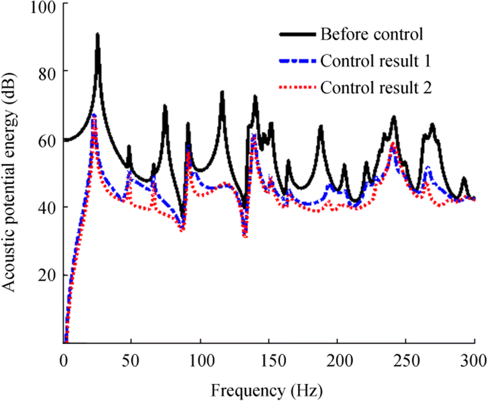 Figure 2 The acoustic potential energy before and after control of cavity 1
The control results of 1 and 2 in Figure 2 represent the outcomes of the two control strategies. The first includes the use of one force and one speaker, while the second involves the use of secondary sources of three force actuators. After the control, the residual acoustic potential energy of the two control strategies is dramatically reduced, and some cavity-dominated peaks such as at 74 Hz and 116 Hz disappeared. When the sound transmission is reduced by three force actuators, the acoustic potential energy reduction is more distinct both at the cavity and subplate dominated levels, which means that the force actuators can achieve substantial noise reduction without the use of acoustic secondary sources.
To investigate the control mechanism, the kinetic energy of each flexible subplate is defined as:
$$ {E}_k=\int {\rho}_s{h}_sv(s)\mathrm{d}s=M{\boldsymbol{V}}^{\mathrm{H}}\boldsymbol{V} $$ (16) Before and after control, the kinetic energy of the two subplates is shown in Figure 3. Since the actuators were installed on the subplate 1, its kinetic energy increased after control, and the increased kinetic energy becomes more evident when three force actuators are used. Meanwhile, the kinetic energy of the second subplate changes slightly after control.
 Figure 3 The kinetic energy of two subplates before and after control
To further explore the control mechanism, the modal amplitudes of two subplates, the acoustic modal amplitudes of the cavity, the acoustic modal amplitudes, and phases induced by two subplates at 91 Hz of using three force actuators are presented in Figure 4, where the acoustic modal amplitudes induced by subplate χ is defined as:
$$ {\boldsymbol{P}}_{\operatorname{int},\chi }={\boldsymbol{\varLambda}}_c{\boldsymbol{B}}_{\chi }{\boldsymbol{V}}_{\chi } $$ (17) 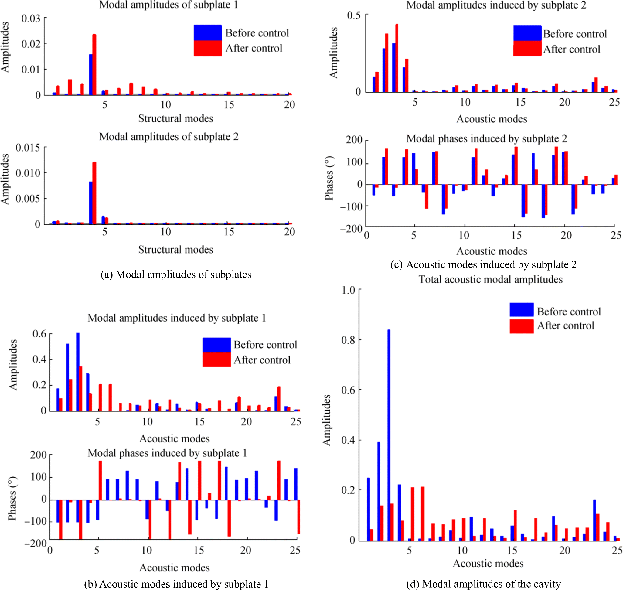 Figure 4 The modal amplitudes and phases of cavity 1 at 91 Hz
Figure 4 a shows the modal amplitudes of subplate 1 and subplate 2 with actuators placed on subplate 1. All the structural modal amplitudes of subplate 1 were increased after control and the fourth modal amplitude of subplate 2 was also increased. However, the acoustic modal amplitudes of the first four dominating modes due to the contribution of subplate 1 were reduced, while the acoustic modal amplitudes of the first four dominating modes from the contribution of subplate 2 were increased, which are shown in Figure 4 b and c. This phenomenon can be explained by checking the phases of two subplates shown in Figure 4 b and c. The phases of the acoustic modes induced by the two subplates were changed after the control, and the differences between them were about 180°, in particular, the first four modes. The first four modal amplitudes of the cavity were reduced by superimposing the contributions of two subplates, which is shown in Figure 4d. Therefore, the variation of the acoustic modal amplitudes induced by two subplates is to change their phases, and the control system's behavior in the multiple supported subplates is not to reduce the radiation of the controlled subplates themselves but to cancel the radiation of all subplates.
4.2 Nine-Subplate Model
Because force actuators can achieve satisfactory results, model 2 shown in Figure 1b uses only three force actuators to control noise transmission in this subsection. Because of the system's symmetry, only subplates 1, 2, and 5 were individually controlled. The actuators' positions on subplate 1 were (0.13 × Lx − 0.05, 0.0.137 × Ly − 0.05, 15), (0.13 × Lx + 0.05, 0.137 × Ly − 0.05, 1.5), and (0.13 × Lx, 0.137 × Ly + 0.05, 1.5). When the actuators are installed on subplates 2 or 5, the same relative positions were adopted.
The acoustic potential energy curves obtained by controlling various subplates are shown in Figure 5. It can be seen that the control results are similar by controlling subplates 1, 2, and 5. All the internal noise is reduced particularly below 130 Hz. Among the three control results, most of the cavity-dominated peaks were reduced after control such as at 51 Hz, 87 Hz, 117 Hz, and 128 Hz, and various subplate-dominated peaks were also attenuated but not completely canceled. Also, after control, the frequencies corresponding to the subplate-dominated peaks were shifted back to the subplates' natural frequencies. For example, the first peak of acoustic potential energy occurs at 25 Hz before control. But, it is shifted to 23 Hz after control, which is the subplate's first natural frequency. It suggests that when we use force actuators to minimize the transmission of sound into a cavity, the control system mechanism aims to reduce the coupling between flexible subplates and the cavity, which explains why acoustic potential energy peaks controlled by the cavity can be totally canceled. Comparing Figure 5 with Figure 2, it can be observed that the results of the controls showed a deterioration as a result of the increase in subplates.
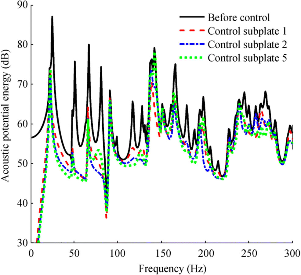 Figure 5 The acoustic potential energy of cavity 2 before and after control
Model 2 subplates' kinetic energy is shown in Figure 6, and only four kinetic energy subplates are shown because of similarity. It can be seen that the kinetic energy of the controlled subplate is increased after control, and the increased energy is much greater than that of model 1, which means that the more subplate of a cavity, the more kinetic energy is increased for the controlled subplate. Notwithstanding, the uncontrolled subplates' kinetic energy remains at a similar level. The control of subplate 5 was taken as an example to investigate the control mechanism, and the modal vibration amplitudes of subplate 5, the acoustic modal amplitudes, the phases caused by subplate 5, and other subplates are shown in Figure 7.
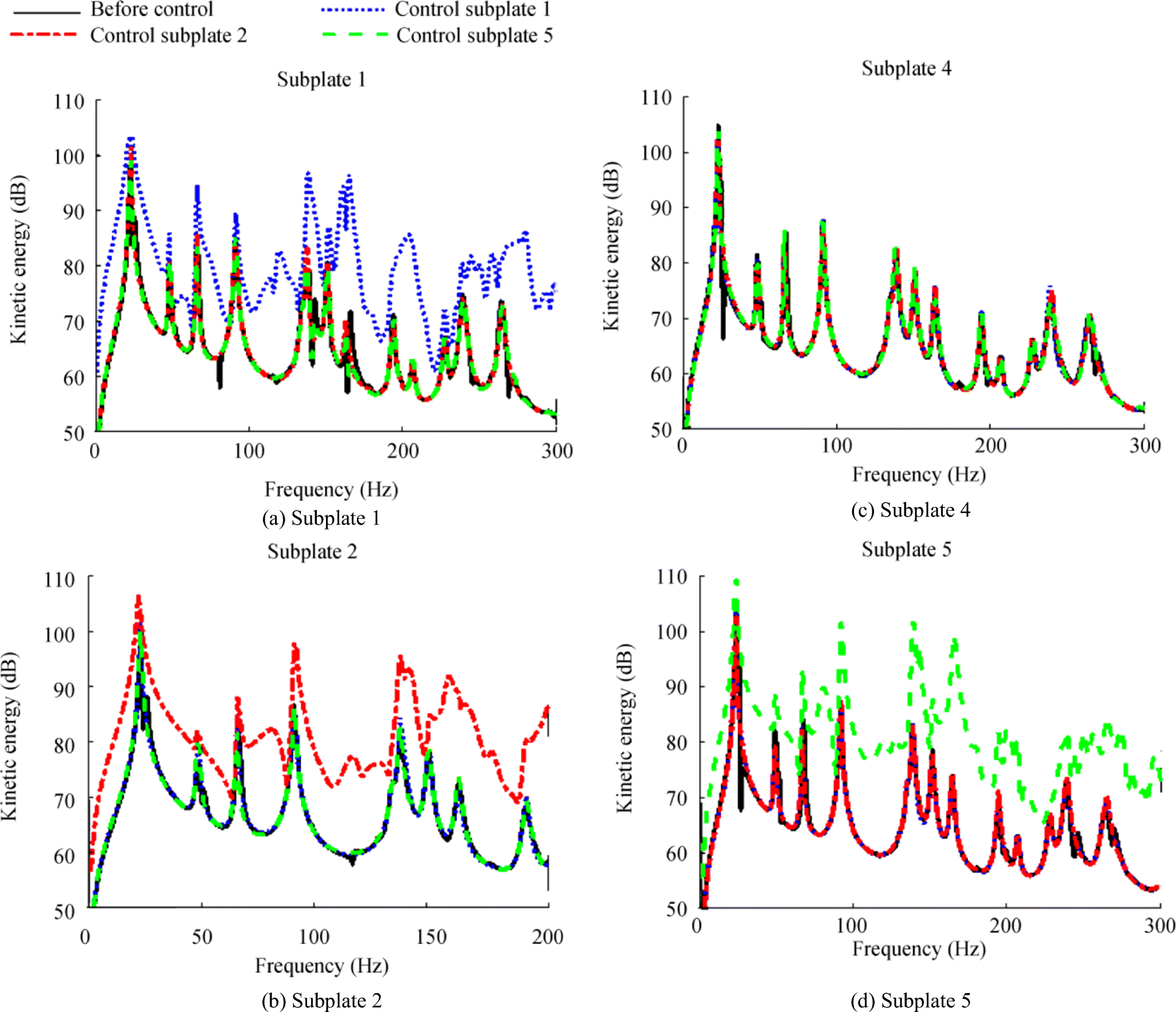 Figure 6 The kinetic energy of four subplates of model 2 before and after control
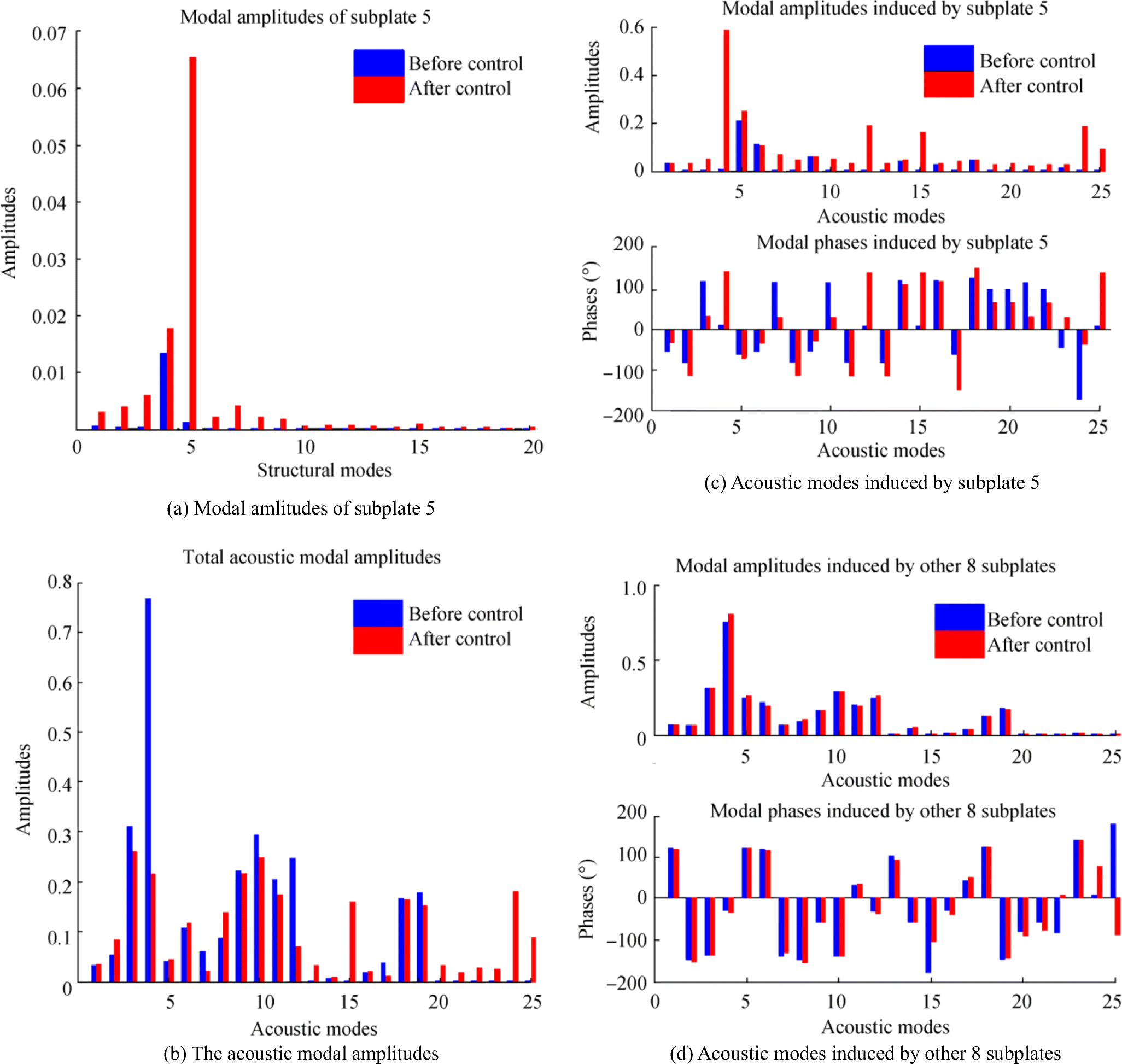 Figure 7 The modal amplitudes and phases of model 2 at 91 Hz
Figure 7 a shows the structural modal amplitudes of subplate 5 before and after control at 91 Hz. Since the excitation frequency is near the fourth natural frequency of the subplate, the fourth modal amplitude is larger than others before the control. It can be observed from Figure 7b that the dominated acoustic mode of the cavity is the fourth mode. After the control, all subplate 5 modal amplitudes were increased, especially the fifth modal amplitude, which increases more than 60 times. And, there is also a significant increase in the fourth acoustic mode amplitude caused by subplate 5 and is shown in Figure 7c. The acoustic modal amplitudes from the contribution of the other 8 subplates are shown in Figure 7d.
To reduce this modal amplitude, since the dominated mode of the cavity is the fourth acoustic mode, an idealistic solution generates an acoustic modal amplitude of the same magnitude but opposite phase to the original one. Because the fourth modal acoustic amplitude induced by subplate 5 is very small before control, the vibration pattern of subplate 5 must be changed to increase the amplitude. Table 4 shows part of the subplate 5 and cavity coupling coefficients, where the numbers in the first column represent the subplate mode number and indicate the cavity's acoustic mode. It can be seen that the structural modes having a coupling relationship with the fourth acoustic mode are fifth and tenth structural modes. Since the excitation frequency is close to the subplate's fifth natural frequency, the fifth mode is easy to excite, which explains why subplate 5's fifth modal amplitude and subplate 5's fourth acoustic mode amplitude is significantly increased after control as shown in Figure 7 a and c. After superposition, radiations from subplate 5 and other 8 subplates canceled each other. So the dominating modal amplitudes of the cavity were reduced, which can be observed from Figure 7b.
Table 4 Coupling coefficients between subplate 5 and the cavity (B5)Mode 1 2 3 4 5 1 0.427 0 0 0 -0.384 2 0 0.110 0 0 0 3 0 0 0.110 0 0 4 0.142 0 0 0 -0.075 5 0 0 0 0.028 0 6 0 0 0.037 0 0 7 0.142 0 0 0 -0.128 8 0 0.054 0 0 0 9 0 0.037 0 0 0 10 0 0 0 0.014 0 5 Conclusions
In this paper, active control sound transmission through multiple independently supported flexible subplates in simplified ship cabins was studied, and the coupling relationships were formulated between each subplate and the cavity. To reduce the acoustic potential energy of the two-subplate and nine-subplate models, different control methods were introduced, and their control results were compared. The results of the simulation show that force actuators can achieve adequate noise reduction efficiency in modes controlled by both the subplate and the cavity without the use of secondary acoustic sources. The force actuators of the control system are effective in controlling the transmission of sound into a structural-acoustic coupling system by reducing the coupling between the flexible subplates and the cavity. In the future, the active noise control system could be integrated into one device with several force actuators and installed on the flexible subplates to reduce the transmission of noise.
Also, when actuators are used to attenuate noise transmission into a cavity via multiple subplates, the control results of the installation of actuators on the central subplate are relatively better, especially to reduce low-frequency noise. However, the results of noise reduction will deteriorate if there are more subplates in a cavity. Besides, the controlled subplate's vibration pattern is modified after regulation to improve the radiation of itself to cancel the radiation of the other subplates instead of the radiation of itself. At the same time, the controlled subplate's vibration increases, and the higher the subplates of a cavity, the greater the increase in kinetic energy. Therefore, for a cavity with many subplates, it is appropriate to control more than one subplates. And thus, the control efficiency could be improved, and the controlled subplate's kinetic energy increment could be relieved.
Appendix
The coupling matrixes between the two subplates and the cavity for model 1 are:
$$ {\boldsymbol{B}}_1\left(l,i\right)={\left(-1\right)}^n\frac{2{uvL}_x{L}_y\left[1-{\left(-1\right)}^u\cos \left(l\pi /2\right)\right]\left[1-{\left(-1\right)}^{v+m}\right]}{\left(4{u}^2-{l}^2\right)\left({v}^2-{m}^2\right){\pi}^2} $$ (A1) $$ {\boldsymbol{B}}_2\left(l,i\right)={\left(-1\right)}^n\frac{2{uvL}_x{L}_y\left[\cos \left(l\pi /2\right)-{\left(-1\right)}^{l+u}\right]\left[1-{\left(-1\right)}^{v+m}\right]}{\left(4{u}^2-{l}^2\right)\left({v}^2-{m}^2\right){\pi}^2} $$ (A2) The coupling matrixes between the nine subplates and the cavity for model 2 are:
$$ {\boldsymbol{B}}_1\left(l,i\right)={\left(-1\right)}^n\frac{9{uvL}_x{L}_y\left[1-{\left(-1\right)}^u\cos \left(l\pi /3\right)\right]\left[1-{\left(-1\right)}^v\cos \left(m\pi /3\right)\right]}{\left(9{u}^2-{l}^2\right)\left(9{v}^2-{m}^2\right){\pi}^2} $$ (A3) $$ {\boldsymbol{B}}_2\left(l,i\right)={\left(-1\right)}^n\frac{9{uvL}_x{L}_y\left[\cos \left(l\pi /3\right)-{\left(-1\right)}^u\cos \left(2l\pi /3\right)\right]\left[1-{\left(-1\right)}^v\cos \left(m\pi /3\right)\right]}{\left(9{u}^2-{l}^2\right)\left(9{v}^2-{m}^2\right){\pi}^2} $$ (A4) $$ {\boldsymbol{B}}_3\left(l,i\right)={\left(-1\right)}^n\frac{9{uvL}_x{L}_y\left[\cos \left(2l\pi /3\right)-{\left(-1\right)}^{u+l}\right]\left[1-{\left(-1\right)}^v\cos \left(m\pi /3\right)\right]}{\left(9{u}^2-{l}^2\right)\left(9{v}^2-{m}^2\right){\pi}^2} $$ (A5) $$ {\boldsymbol{B}}_4\left(l,i\right)={\left(-1\right)}^n\frac{9{uvL}_x{L}_y\left[1-{\left(-1\right)}^u\cos \left(l\pi /3\right)\right]\left[\cos \left(m\pi /3\right)-{\left(-1\right)}^v\cos \left(2m\pi /3\right)\right]}{\left(9{u}^2-{l}^2\right)\left(9{v}^2-{m}^2\right){\pi}^2} $$ (A6) $$ {\boldsymbol{B}}_5\left(l,i\right)={\left(-1\right)}^n\frac{9{uvL}_x{L}_y\left[\cos \left(l\pi /3\right)-{\left(-1\right)}^u\cos \left(2l\pi /3\right)\right]\left[\cos \left(m\pi /3\right)-{\left(-1\right)}^v\cos \left(2m\pi /3\right)\right]}{\left(9{u}^2-{l}^2\right)\left(9{v}^2-{m}^2\right){\pi}^2} $$ (A7) $$ {\boldsymbol{B}}_6\left(l,i\right)={\left(-1\right)}^n\frac{9{uvL}_x{L}_y\left[\cos \left(2l\pi /3\right)-{\left(-1\right)}^{u+l}\right]\left[\cos \left(m\pi /3\right)-{\left(-1\right)}^v\cos \left(2m\pi /3\right)\right]}{\left(9{u}^2-{l}^2\right)\left(9{v}^2-{m}^2\right){\pi}^2} $$ (A8) $$ {\boldsymbol{B}}_7\left(l,i\right)={\left(-1\right)}^n\frac{9{uvL}_x{L}_y\left[1-{\left(-1\right)}^u\cos \left(l\pi /3\right)\right]\left[\cos \left(2m\pi /3\right)-{\left(-1\right)}^{v+m}\right]}{\left(9{u}^2-{l}^2\right)\left(9{v}^2-{m}^2\right){\pi}^2} $$ (A9) $$ {\boldsymbol{B}}_8\left(l,i\right)={\left(-1\right)}^n\frac{9{uvL}_x{L}_y\left[\cos \left(l\pi /3\right)-{\left(-1\right)}^u\cos \left(2l\pi /3\right)\right]\left[\cos \left(2m\pi /3\right)-{\left(-1\right)}^{v+m}\right]}{\left(9{u}^2-{l}^2\right)\left(9{v}^2-{m}^2\right){\pi}^2} $$ (A10) $$ {\boldsymbol{B}}_9\left(l,i\right)={\left(-1\right)}^n\frac{9{uvL}_x{L}_y\left[\cos \left(2l\pi /3\right)-{\left(-1\right)}^{u+l}\right]\left[\cos \left(2m\pi /3\right)-{\left(-1\right)}^{v+m}\right]}{\left(9{u}^2-{l}^2\right)\left(9{v}^2-{m}^2\right){\pi}^2} $$ (A11) -
Figure 1 Structural-acoustic coupling models
Figure 2 The acoustic potential energy before and after control of cavity 1
Figure 3 The kinetic energy of two subplates before and after control
Figure 4 The modal amplitudes and phases of cavity 1 at 91 Hz
Figure 5 The acoustic potential energy of cavity 2 before and after control
Figure 6 The kinetic energy of four subplates of model 2 before and after control
Figure 7 The modal amplitudes and phases of model 2 at 91 Hz
Table 1 Properties of subplates
Young's modulus (GPa) Thickness (mm) Density (kg/m3) 60 5 2400 Table 2 Properties of the incident sound
Incident angle Density (kg/m3) Speed (m/s) (45°, 135°) 1.21 344 Table 3 Modal frequencies of the subplate and cavities
Subplate Cavity 1 Cavity 2 Modes Frequency (Hz) Modes Frequency (Hz) Modes Frequency (Hz) (1, 1) 22.95 (0, 0, 0) 0 (0, 0, 0) 0 (2, 1) 48.54 (1, 0, 0) 73.50 (1, 0, 0) 49.00 (1, 2) 66.20 (0, 0, 1) 114.67 (0, 1, 0) 63.70 (3, 1) 91.19 (1, 0, 1) 136.20 (1, 1, 0) 80.37 (2, 2) 91.79 (2, 0, 0) 147.01 (2, 0, 0) 98.01 (3, 2) 134.44 (2, 0, 1) 186.44 (0, 0, 1) 114.67 (1, 3) 138.28 (0, 1, 0) 191.11 (2, 1, 0) 116.89 (4, 1) 150.91 (1, 1, 0) 204.76 (1, 0, 1) 124.70 (2, 3) 163.87 (3, 0, 0) 220.51 (0, 2, 0) 127.41 (4, 2) 194.16 (0, 1, 1) 222.87 (0, 1, 1) 131.17 Table 4 Coupling coefficients between subplate 5 and the cavity (B5)
Mode 1 2 3 4 5 1 0.427 0 0 0 -0.384 2 0 0.110 0 0 0 3 0 0 0.110 0 0 4 0.142 0 0 0 -0.075 5 0 0 0 0.028 0 6 0 0 0.037 0 0 7 0.142 0 0 0 -0.128 8 0 0.054 0 0 0 9 0 0.037 0 0 0 10 0 0 0 0.014 0 -
Al-Bassyiouni M, Balachandran B (2005) Sound transmission through a flexible panel into an enclosure: structural-acoustics model. J Sound Vib 284(1–2): 467–486. https://doi.org/10.1016/j.jsv.2004.06.040 Amromin E (2018) Ships bottom cavities as shock absorbers in waves. J Mar Sci Appl 17(2): 173–177. https://doi.org/10.1007/s11804-018-0019-3 Ankit DN (2018) Free flexural vibration of a partially wet tapered Timoshenko beam with intermittent mass and stiffness variations, eccentric tip mass and non-classical foundation. J Mar Sci Appl 17: 498–509. https://doi.org/10.1007/s11804-018-0035-3 Borelli D, Gaggero T, Rizzuto E, Schenone C (2016) Holistic control of ship noise emissions. Noise Mapping 3(1): 107–119. https://doi.org/10.1515/noise-2016-0008 Cheer J, Elliott S (2016) Active noise control of a diesel generator in a luxury yacht. Appl Acoust 105: 209–214. https://doi.org/10.1016/j.apacoust.2015.12.007 Cui HF, Chen N (2012) Active control of sound radiation and transmission into a cavity consisting of multi-flexible plates. Noise Control Eng J 60(5): 492–506. https://doi.org/10.3397/1.3701027 Du Y, Zhang J (2012) Structural-acoustic coupling characteristics of a rectangular enclosure with lightweight design considerations. Noise Control Eng J 60(6): 726–739. https://doi.org/10.3397/1.3701044 Fahy F, Gardonio P (2007) In: 2nd (ed) Sound and structural vibration: radiation, transmission and response. Academic Press, Jordan Hill, pp 227–400 Hansen C, Snyder S, Qiu X, Brooks L, Moreau D (2012) Active control of noise and vibration. 2nd ed., CRC Press, 15–185 Hasheminejad SM, Shakeri R (2017) Active transient acousto-structural response control of a smart cavity-coupled circular plate system. Arch Acoustics 42(2): 273–286. https://doi.org/10.1515/aoa-2017-0030 Jin GY, Liu ZG, Yang TJ (2009) Active control of sound transmission into an acoustic cavity surrounded by more than one flexible plate. Noise Control Eng J 57(3): 210–220. https://doi.org/10.3397/1.3097762 Kandouci C, Adjal Y (2014) Forced axial and torsional vibrations of a shaft line using the transfer matrix method related to solution coefficients. J Mar Sci Appl 13(2): 200–205. https://doi.org/10.1007/s11804-014-1251-0 Kim SM, Brennan MJ (2000) Active control of harmonic sound transmission into an acoustic enclosure using both structural and acoustic actuators. J Acoust Soc Am 107(5): 2523–2534. https://doi.org/10.1121/1.428640 Kletschkowski T (2012) Adaptive feed-forward control of low frequency interior noise. Springer Science & Business Media, Hamburg, pp 3–24 Kurt RE, Khalid H, Turan O, Houben M, Bos J, Helvacioglu IH (2016) Towards human-oriented norms: considering the effects of noise exposure on board ships. Ocean Eng 120: 101–107. https://doi.org/10.1016/j.oceaneng.2016.03.049 Liang BN, Yu HL (2013) Finite element parametric acoustic modeling and analysis of ship floating cabins. Appl Mech Mater 333-335: 2146–2150. https://doi.org/10.4028/www.scientific.net/AMM.333-335.2146 Naveen G, KUMAR A, Sagar M (2014) Parametric sensitivity analysis of factors affecting sound transmission loss of multi-layered building elements using Taguchi method. Arch Acoustics 39(2): 165–176. https://doi.org/10.2478/aoa-2014-0020 Nelson PA, Curtis ARD, Elliott SJ, Bullmore AJ (1987) The active minimization of harmonic enclosed sound fields, part Ⅰ: theory. J Sound Vib 117(1): 1–13. https://doi.org/10.1016/0022-460X(87)90432-9 Pan J, Hansen CH (1991) Active control of noise transmission through a panel into a cavity. Ⅱ: experimental study. J Acoust Soc Am 90(3): 1488–1492. https://doi.org/10.1121/1.401887 Pan J, Hansen CH, Bies DA (1990) Active control of noise transmission through a panel into a cavity: Ⅰ. analytical study. J Acoust Soc Am 87(5): 2098–2108. https://doi.org/10.1121/1.399555 Sadri M, Younesian D (2015) Vibro-acoustic analysis of a coach platform under random excitation. Thin-Walled Struct 95: 287–296. https://doi.org/10.1016/j.tws.2015.07.008 Snyder SD, Tanaka N (1993) On feedforward active control of sound and vibration using vibration error signals. J Acoust Soc Am 94(4): 2181–2193. https://doi.org/10.1121/1.407489 Tanaka N, Kobayashi K (2006) Cluster control of acoustic potential energy in a structural/acoustic cavity. J Acoust Soc Am 119(5): 2758–2771. https://doi.org/10.1121/1.2188815 Wang C, Qiu ZP, Wang XJ, Wu D (2014) Interval finite element analysis and reliability-based optimization of coupled structural-acoustic system with uncertain parameters. Finite Elem Anal Des 91: 108–144. https://doi.org/10.1016/j.finel.2014.07.014 Wang G, Cui XY, Liang ZM, Li GY (2015) A coupled smoothed finite element method (S-FEM) for structural-acoustic analysis of shells. Finite Elem Anal Des 61: 207–217. https://doi.org/10.1016/j.enganabound.2015.07.017 Wszołek T (2017) Cumulative industrial noise impact on the environment. Arch Acoustics 42(2): 169–174. https://doi.org/10.1515/aoa-2017-0019 Xu YL, Huang XS, Zhu LT, Huang DY (2017) Numerical analysis and optimization of noises of ship cabins in the low frequency. J Vibroeng 19(3): 2234–2246. https://doi.org/10.21595/jve.2017.17933 Yang TJ, Zhu LP, Li XH, Zhu MG, Pang LH (2017) Investigation on active control for sound transmission through a panel comprised of several flexible plates to the cavity. INTER-NOISE and NOISE-CON Congress Conf Proc 255(5): 2055–2064 Zhang WC (2017). Simulation od mid-high vibro-acoustic in ship cabins and resear of its transmission path. PhD thesis, Dalian Maritime University, Dalian, 10–20. (in Chinese)