Experimental Study on Coupled Motions of Mother Ship Launching and Recovering of Human-Occupied Vehicle in Regular Waves
https://doi.org/10.1007/s11804-019-00114-5
-
Abstract
The launching and recovery process of a human-occupied vehicle (HOV) faces more complex wave effects than other types of submersible operations. However, due to the nonlinearity between the HOV and its mother ship, difficulties occur in theoretically simulating their coupled motion and hydrodynamics. The coupled motion responses and the load under different regular wave conditions are investigated experimentally in this study. The optimized design of the experimental scheme simulated the launching and recovery process of the mother ship and HOV in regular waves. The attitude sensor performed synchronous real-time measurement of the coupled motion between the mother ship and HOV as well as obtained the load data on the coupled motion under different cable lengths. The results show that models in heading waves mainly lead to the vertical motion of the hoisting point. In beam waves, the transverse and vertical motions of the hoisting point occur in a certain frequency of waves. Under the heading and beam wave conditions, the longer the hoisting cable is, the greater the movement amplitude of the submersible is. Moreover, compared with the condition of the beam waves, the hoisting submersible has less influence on the mother ship under the condition of the heading waves. The findings provide theoretical support for the design optimization of the launching and recovery operation.Article Highlights•With the comparisons of the experimental and numerical results, this paper analyzed the impactions of the cable length on the motion response during recovering.•The experimental scheme for the motions of HOV and its mother ship with various regular waves was introduced in this paper.•The motion response and load tests of the HOV and its mother ship were carried out with the regular waves, whereafter the movement rule of hoisting point was presented.•The interactions between the HOV and its mother ship were figured out in launching and recovering. -
1 Introduction
Human-occupied vehicles (HOVs) have been widely used in deep-sea exploration, enabling researchers to reach the deep sea in real-time with the advantage that remotely operated vehicles (ROVs) and autonomous underwater vehicles (AUVs) cannot achieve (Liu et al. 2017; Hu et al. 2016). Once researchers and precision instruments are involved in the HOV, the launching and recovering system (LRS) of the mother ship becomes crucial and will directly affect the HOV performance. Under the influence of wind and wave, the ship will have an unexpected motion, which will lead to a large amplitude movement of LRS and HOV. In addition, this situation will introduce additional loads on structures, causing the collision between HOV and ship. The HOVs Alvin (Vedachalam et al. 2014) and Jiaolong (Cui et al. 2012) have suffered similar accidents, which have caused difficulties in normal launching and recovery. Therefore, studying the coupling motion response of the HOV and its mother ship is necessary for the design and safe operation of an LRS. An advanced and reliable LRS can directly improve the marine operations safety and efficiency of HOVs. Therefore, key issues have drawn much attention among researchers, such as buffer protection, automatic connecting, wind compensation, constant tension cable arrangement (Zhang et al. 2012), and objects that influence the dynamic response of mother ship launching and recovering. Furthermore, some issues mainly focus on the effects of LRS components on its dynamic response. Considering basic crane maneuvers, such as cable reeling and unreeling, Ren et al. (2007) conducted numerical studies on the dynamic response of the cargo by using a dynamic model of nonlinear three-dimensional lifting load system based on the general form of Lagrange's equation. Furthermore, Wang et al. (2010) analyzed the effects of cable length, external excitation frequency, and hoisting motion on dynamic response characteristics of the suspension system; in their study, the nonlinear dynamic equations of Lagrange method and ADAMS software are used to verify the rationality of the established dynamic model. Cha et al. (2010) used dynamic motion equations based on multi-body system dynamics to estimate the six degree-of-freedom (DOF) motions of the floating crane and heavy cargo by calculating the wire rope tension between them. At the same time, other researchers focused on the effects of flow-field environment, such as waves, on the performance of the mother ship or LRS. Considering the operation in regular waves, Jin et al. (2015) set up a 3D nonlinear hoisting system kinematic model and analyzed its oscillation characteristics, which also discussed the effects of wave direction, wave frequency, and hoisting speed on the swinging angle and cable tension. For irregular waves, Jin et al. (2016) investigated the nonlinear coupling mechanism among the movement of the ship, umbilical cable, and seafloor drill. Thereafter, Jin et al. (2016) calculated and analyzed the movement of the seafloor drill and the umbilical cable tension of the seafloor drill before entering water and at different water depths.
In fact, various numerical studies have been conducted on these subjects, but few researchers have conducted experimental research on them. Considering the influence of water depth on a moored floating crane ship, Dong et al. (2012) performed a model test at 46 m and 36 m water depths with model scale 1:50. The results showed that with the decrease of water depth, the effect of shallow water on the second-order load becomes the main reason for the increasingly tense mooring force, while its contribution to the first-order load is less. Xu et al. (2014) used numerical and experimental methods to study the full-lifting and empty-lifting performance of semi-submersible crane vessels during lifting operations; they found that the vessel has a favorable hydrodynamic behavior in a particular sea state and the loads on the equipment are safe enough. However, not only can the flow-field environment affect the motion of the mother ship but the dynamic tension induced by the lifted object can also affect its motion responses. Nam et al. (2017) investigated the coupled motion responses of a floating crane vessel and a lifted subsea manifold during deep-water installation operations in their experiments, in which the vessel with a crane control system and a typical subsea manifold were also examined. Other researchers also discussed the structural style or new design scheme of LRS. Lee (2016) surveyed and categorized various types of LRS fitted to specific manned platforms (surface or sub-surface). Sarda and Dhanak (2017) described a concept design for automatic launch and recovery of a small AUV from an unmanned surface vehicle and assessed its feasibility through modeling and simulation.
According to the preceding analysis, few studies have been conducted on the coupling motion response of the mother ship and submersible when they conduct the launching and recovering missions in waves. In addition, the wave direction, wave length, and length of the hoisting wire are essential for the LRS operation. However, few investigations on the LRS operation have been conducted, especially on the experimental method. Therefore, in this paper, we analyzed the wave and hoisting wire effects on the mother ship and also examined the model experiments of LRS and HOV in the wave tank with different wave forms. The results can provide a reference for the safe recovery and launching of HOVs in complex sea environments in the future.
2 Experimental Settings
2.1 Models of Mother Ship and HOV
The experimental models include a mother ship and a submersible vehicle. Considering the dimension of the towing tank and the Jiaolong HOV, we built these models by scaling the mother ship and HOV. The scale ratio of the models is γ = 35. According to ITTC 7.5-02-07-04.5, the damping forces and fluid inertia forces satisfy the Froude similarity criterion and contribute more to the wave load than the viscous force. The scale effects are negligible particularly in the vertical wave force and moment, and the model experiments can reflect this condition in real ship navigations.
The parameters of the mother ship and HOV with their models are shown in Tables 1 and 2, respectively.
Table 1 Parameters of mother ship and its modelParameters Mother ship Model Ship length (m) 100 2.86 Design waterline length (m) 95 2.71 Molded breadth (m) 18 0.51 Molded depth (m) 8 0.23 Designed draft (m) 5 0.14 Designed displacement (N) 39000 9.10 Height of center-of-gravity (m) 7.688 0.22 Table 2 Parameters of HOV and its modelParameters HOV Model Submersible length (mm) 7000 200 Submersible breadth (mm) 2700 77 Submersible height (mm) 2700 77 Draft of floating state (mm) 2350 67 Full load weight (N) 148000 3.47 The mother ship is made up of a glass-fiber reinforced plastic shell and inner frame. In the experiments, the ship model should meet the following requirements: the main dimensions should be geometrically similar to that of the mother ship, and the weight, center-of-gravity position, and moment of inertia of each axis are similar to those of the mother ship. A similar weight can be achieved by setting a kentledge in the ship model, and a similar moment of inertia can be met by adjusting the inertia frame fixed on the deck of the ship model. The HOV model is made of PLA plastic through 3D printing. A watertight slot and a water tank are set into the HOV model for sensors to measure its motions and adjust the HOV floating condition, as shown in Fig. 1.
 Figure 1 HOV model. a Upper parts of HOV model. b Lower parts of HOV model
The design of LRS is composed of A-frame, swing frame, heave compensation winch, vibration reducing frame, telescopic frame, loading vehicle, and track for submersible, as shown in Fig. 2. Owing to the limitation of the model scale, we use a spring set instead of a heave compensation winch in the experiments and cancel the cable winch. Thus, the length of the cable for hoisting the submersible remains the same in each individual trial. The LRS, which is placed in the middle of the ship stern, can flush to change the height. At the position of the port side of the ship model, close to the frame base, we set a flat and paste three acceleration sensors to measure the acceleration of the hoisting point.
 Figure 2 LRS. a 3D model: 1, mother ship; 2, frame base; 3, hydraulic cylinder; 4, spring set; 5, cable; 6, A-frame; 7, hoist point; 8, tension sensor; 9, submersible; 10, acceleration sensor. b Design and sensor position set
2.2 Conditions of Experiments
The experiments of the motion response for ships and submersibles in regular waves were performed in the towing tank laboratory of Harbin Engineering University. The scale of the tank is length × width × depth = 108 m × 7 m × 3.5 m. A wave maker is set on one side of the tank and a dock on the other side. The wave environment, which is needed in experiments, is created by the flap-type wave maker and can generate a regular wave period in the range of 0.4-4 s and maximum wave height of 0.4 m (Liu et al. 2016). Figure 3 shows the tank and trailer, and Fig. 4 presents the wave maker.
 Figure 3 Experimental towing tank and trailer
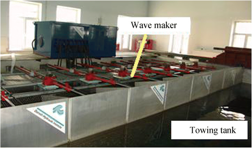 Figure 4 Flap-type wave maker
Other instruments and equipment used in the experiments include the following:
1) The motions and forces of the ship model were measured by a four-DOF motion recorder with model GEL-421-1 and its force measurement range T ≤ 100 N, heaving range = ± 200 mm, surging range = ± 400 mm, roll angle range = ± 50°, pitch angle range = ± 50°, and accuracy = 0.1%.
2) The pitch and roll angles and corresponding accelerations of ship were obtained by an InnaLabs AHRS system that included two parts of sensor and software. The sampling frequency was 1-100 Hz and course angle range = ± 180°, pitch angle range = ± 90°, and roll angle range = ± 180°.
3) The traction force of the cable was measured by low tension and compression sensor (USA Interface WMC series load cell) with an all-stainless-steel airtight structure and power supply < 12 VDC with export 2 mV/V, accuracy < ± 0.2%, working temperature - 54 to 121 ℃, and measuring range 5-500 lbf.
4) To collect signals in the time and frequency domains from other instruments and conduct spectrum analysis as well as real-time data processing, a DongHua DH5920 dynamic signal selecting and analysis system is adopted, while its number of work channel is 16, and the sampling frequency is 10-100 kHz. The accuracy of this system is smaller than 0.5% and its stability is 0.05%/h.
5) An accelerometer (Kistler 8310) is set to measure the acceleration of models. Its sampling frequency is 0-250 Hz and nonlinear deviation < ± 0.8%, working temperature − 40 to 85 ℃, and temperature influence 0.02%/℃.
2.3 Experimental Schemes
2.3.1 Free Decay Rolling Experiment for Ship Model
In the experiments, we measured the motion and force of the model in waves using a 4D seaworthiness instrument. We also measured the height of the center-of-gravity and moment of inertia using a measuring frame, and the course angle, pitch and roll angle, angular velocity, and accelerations using an electronic gyroscope. Furthermore, the wave produced by the wave maker is tested by a wave height gauge to satisfy the experimental requirement.
Once the relevant equipment calibration was completed, we adjusted the weight, the height of the center-of-gravity, and moment of inertia for the ship model by kentledge and moment measuring frame to keep the model similar with the mother ship and ensure the effectiveness of the experiment. Based on the preceding conditions, we conducted the free decay rolling experiment in calm water at zero speed to achieve the natural period of ship roll motion Tφ and nondimensional roll-damping coefficient 2 μ. Then, we were able to obtain the rolling moment of inertia with added water mass. In the experiments, the seaworthiness was initially fixed on the trailer and its attitude angle measurer should be arranged in transverse direction. The ship model, with modulated weight, the height of the center-of-gravity, and moment of inertia, is related to the seaworthiness. The attitude angle measurer must be located at the longitudinal section in the center plane of the model in transverse direction and the height of the center-of-gravity position in longitudinal direction. The distance from the centerline of the seaworthiness rotating shaft to the baseline of the model keel must be equal to the height of the center-of-gravity in the vertical direction. Then, the ship model can roll around the seaworthiness rotating shaft. Therefore, the rolling motion of the model can be considered as if it is rotating around the axis, passing the height of the center-of-gravity approximately when the model rolls in a small angle. Finally, we press down on one side of the ship and ensure that it has a certain angle heeling (within the limit of the water inlet), and thereafter, we release it to roll freely and record the damped oscillation curves. We repeat this experiment several times to improve the testing accuracy. The results of the repeated experiment showed high consistency and the data coverage rate was more than 95%.
2.3.2 Motion Response Tests for Ship Model
Based on the free decay rolling experiment of the ship model, we conducted the motion response experiments for the ship model at zero speed in head and beam waves, as shown in Fig. 5. These experiments enabled us to obtain the motion amplitude-frequency response curves of the model in waves and calculate the response amplitude further. According to the experimental results mentioned, the motion of the ship in waves can be forecasted. In these experiments, the height of the regular wave is set to 1/30-1/50 times the ship length and the wavelength is 0.5-2 times. The produced waves are 2D long-crested waves and the model would mainly take the motion of pitch, surge, and heave. Thus, the movement of the hoisting point, which is located at the rear of the model, can be considered to remain in the XZ plane. This movement is needed only to measure degrees of random motions by seaworthiness and the acceleration in the X and Z directions by sensors. Similarly, when in beam waves, the ship model would mainly take the motion of roll, sway, and heave. At the same time, the hoisting point keeps movements in the YZ plane.
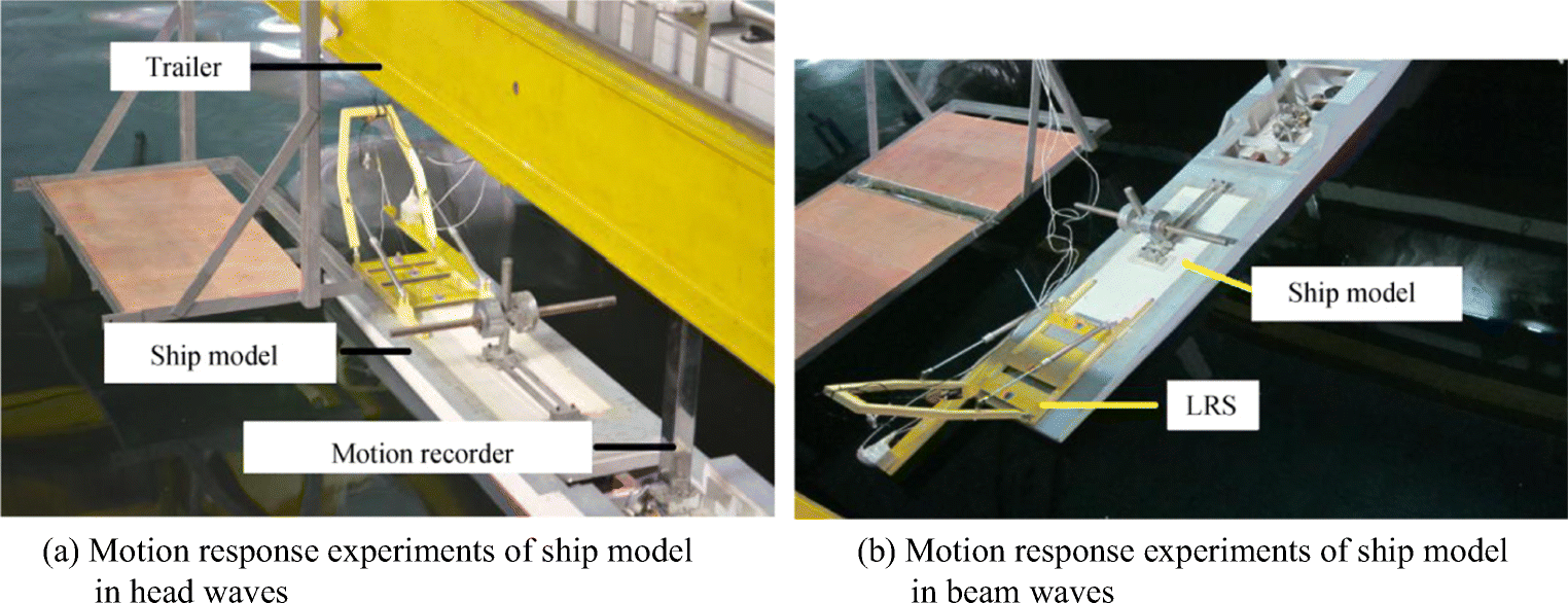 Figure 5 Motion response experiments of ship model in head and beam waves. a Motion response experiments of ship model in head waves. b Motion response experiments of ship model in beam waves
2.3.3 Motion Response Tests of Hoisting HOV by Ship Model
Finally, the motion response experiments, when the ship model launches and recovers the submersible model, are conducted, and the acceleration and angular velocity of both models in every direction are measured. The important consideration is the absence of spring in the cable, and the wave height and length are kept the same as those in the previous experiment. These experiments mainly focus on the state of floating, partly out of water, just out of water, and all close to the vibration reduction frame for the submersible model, as shown in Fig. 6. The motions of the mother ship model have also been measured to compare with those in the previous experiment, which did not hoist the submersible, to study the launching and recovering submersible effect on the mother ship motions.
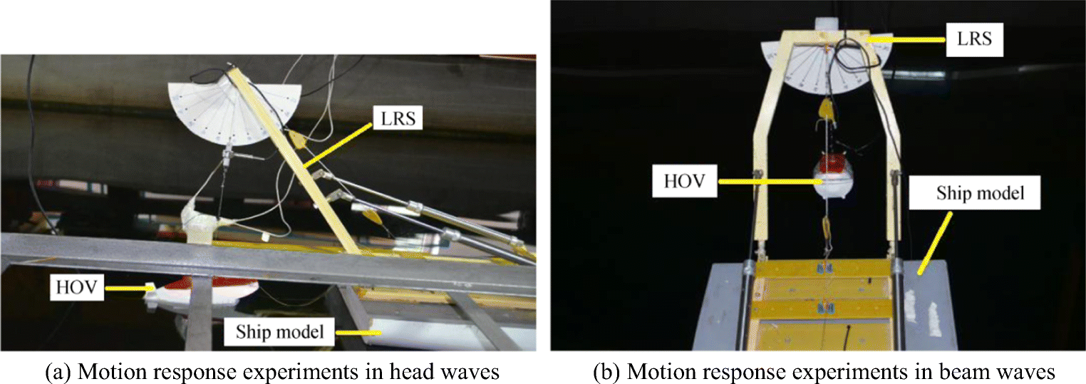 Figure 6 Motion response experiments on ship launching and recovering HOV in head and beam waves. a Motion response experiments in head waves. b Motion response experiments in beam waves
3 Experimental Results and Analysis
3.1 Motion Response Experiments of Ship Model in Waves
Figure 7(a) and (b) show the motion RAOs of the ship model and hoisting point when the wave heading is 180°. M represents the heave motion amplitude of the ship model; H is the wave height; β is the pitch angle of the ship model; φ is the slope of wave surface; O is the surge motion amplitude of the ship model; Px and Pz are the mean longitudinal and vertical displacements of the hoisting point, respectively; and Ax and Az indicate the longitudinal and vertical accelerations of the hoisting point, respectively. Heave and pitch RAOs show typical motion responses of the vessel under head sea conditions. The maximum pitch motion of the vessel is approximately 0.86° per unit incident amplitude when the wave frequency $ \omega \sqrt{L/\mathrm{g}} $ is approximately 1.33, where L = 2.71 m. Once the wave length is similar to the vessel length at approximately $ \omega \sqrt{L/\mathrm{g}} $ = 2.7, the pitch motion slightly decreases due to the cancelation effect, and the heave motion increases locally.
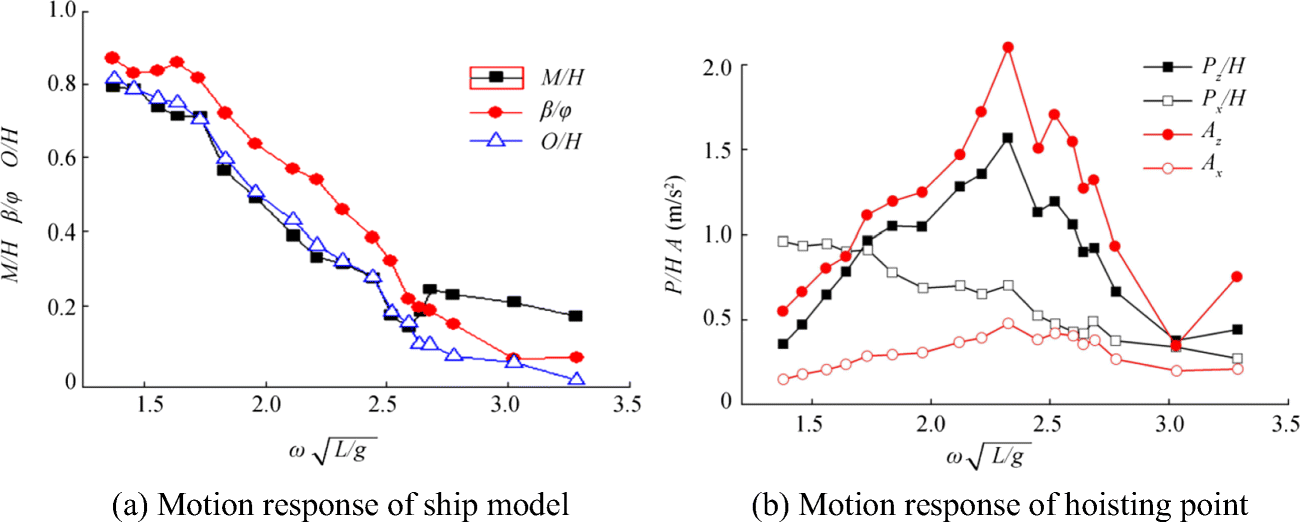 Figure 7 Motion response curves in head waves. a Motion response of ship model. b Motion response of hoisting point
Compared with the conditions shown in Fig. 7(a) and (b), when $ \omega \sqrt{L/\mathrm{g}} $ changes from 1.84 to 2.63, Pz is larger than the wave height and the heave amplitude of the ship in the same wave frequency. When $ \omega \sqrt{L/\mathrm{g}} $ = 2.21, Pz and Az reach the peak value; at this time, Pz/H = 1.57 and Az = 2.11 m/s2. Compared with the longitude motion of the hoisting point, the vertical motion is more violent and this vertical motion determines the cable tension. Therefore, the most dangerous situation occurs when the wave length is equal to the ship length as the tension force increases to the maximum value at this time. In addition, when $ \omega \sqrt{L/\mathrm{g}} $ changes from 1.73 to 2.21, the pitch RAO does not change considerably, the hoisting point changes rapidly, and the wave length corresponds to 2.37-5.69 m, which is equal to two times the ship length.
When the ship model was tested in wave heading 90°, the motion RAOs of the ship model and hoisting point are shown in Fig. 8(a) and (b), respectively. In Fig. 8, α represents the roll angle of the ship model, N is the swaying motion amplitude of the ship model, and Py and Ay are the transverse displacement and acceleration, respectively.
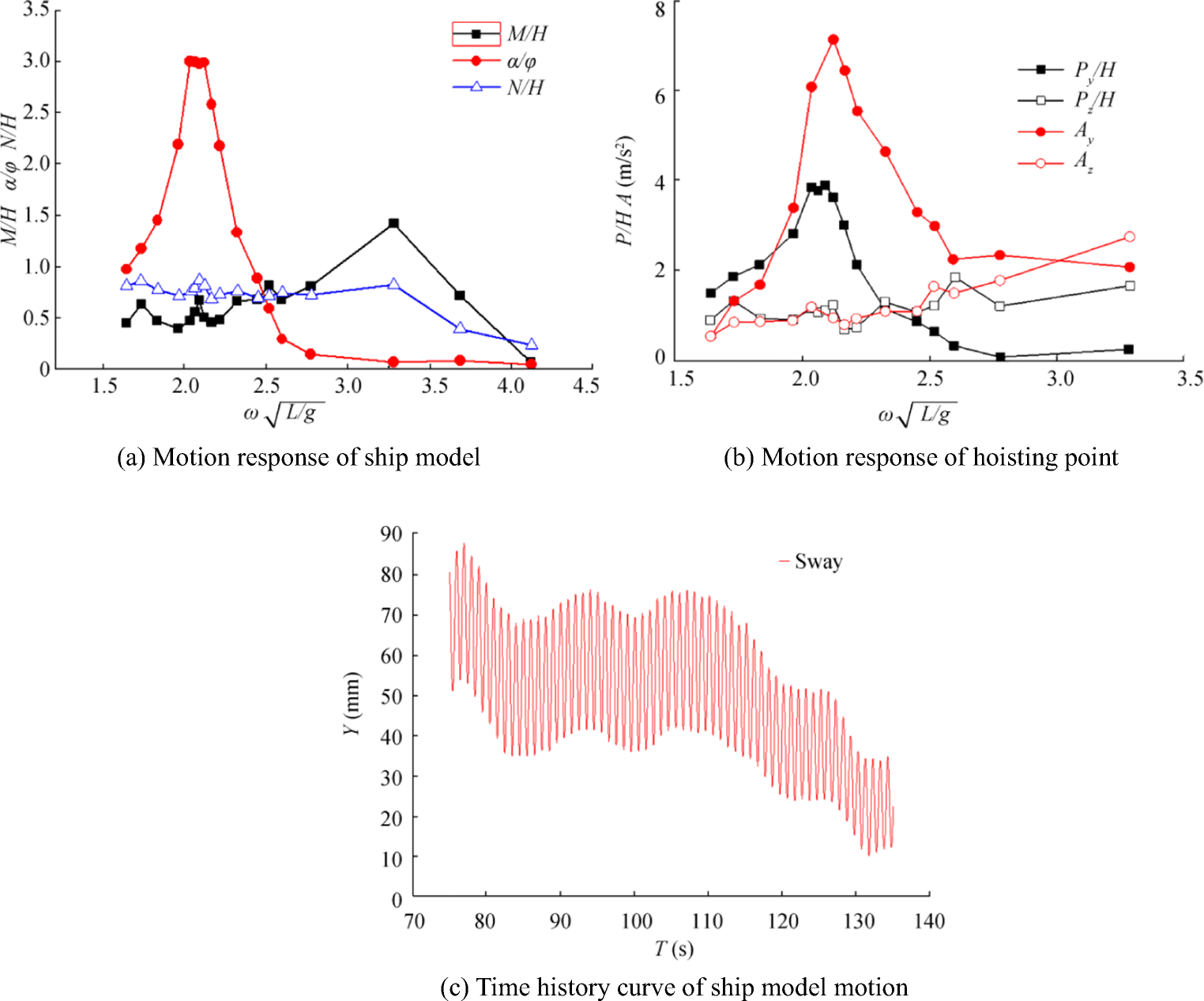 Figure 8 Motion response curves in beam waves. a Motion response of ship model. b Motion response of hoisting point. c Time history curve of ship model motion
In Fig. 8(a), when $ \omega \sqrt{L/\mathrm{g}} $= 3.29, M/H reaches the maximum value 1.62 and its trends are different with those in head waves. When $ \omega \sqrt{L/\mathrm{g}} $= 2.11, α/φ reaches the maximum value 3.21 and its trends are similar to those in the heading waves, while the frequency ω is not equal to the heading wave condition. When $ \omega \sqrt{L/\mathrm{g}} $ < 3.29 in the beam waves, the ratio of the sway amplitude of the ship model to the wave height N/H fluctuates around 0.8, and N/H diminishes rapidly when $ \omega \sqrt{L/\mathrm{g}} $ > 3.29. Furthermore, the time history curve of the ship model motion shows that the ship model has an obvious diffuse drift, that is, the ship model deviates from its initial position gradually. This phenomenon is harmful for launching and recovering the submersible vehicle.
The RAOs of displacement and acceleration for the hoisting point are shown in Fig. 8(b). Py/H and Ay first increase and then decrease. They reach the maximum value Py/H = 3.89 and Ay = 7.14 m/s2 at $ \omega \sqrt{L/\mathrm{g}} $= 2.11. Meanwhile, the fluctuations of Pz/H and Az rise with increasing $ \omega \sqrt{L/\mathrm{g}} $. In comparison, when $ \omega \sqrt{L/\mathrm{g}} $ changes from 1.84 to 2.45, Ay is two times larger than Az, which indicated that transverse motion is evident for the hoisting point. Actually, this transverse motion can affect the swing amplitude of the hoisting point, and the swing amplitude can also reach the maximum value when $ \omega \sqrt{L/\mathrm{g}} $= 2.11, which indicates that HOV is more likely to collide with the LRS. However, Ay is similar to Az when $ \omega \sqrt{L/\mathrm{g}} $ < 1.84 or $ \omega \sqrt{L/\mathrm{g}} $ > 2.45, and the hoisting point exhibits transverse and vertical motions. Compared with what is shown in Fig. 8 (a) and (b), the rolling motion of the mother ship is larger while its swaying motion is small. Then, the transverse motion of the hoisting point is mainly determined by the rolling motion of the mother ship rather than the swaying motion.
In addition, some results can be obtained from Figs. 7(b) and 8(b), when $ \omega \sqrt{L/\mathrm{g}} $ ≤ 2.21, Py is significantly larger than Px in the heading waves. Thus, we should adjust the state of the mother ship according to the wave frequency to reduce the movement amplitude of the hoisting point when $ \omega \sqrt{L/\mathrm{g}} $ ≥ 2.21, Py < Px, and $ \omega \sqrt{L/\mathrm{g}} $ > 2.63, Py < H/4 in practice. The fluctuations of Pz in the beam waves are more violent than those in the head waves and their amplitudes are larger than the wave length. As a result, the wave length is longer than the ship breadth when the mother ship is in the beam waves, which may cause the ship to have an obvious heaving motion following the wave peak and valley. However, Pz decreases with the increasing $ \omega \sqrt{L/\mathrm{g}} $ in the head waves because the ship length is in the range of one or half wave length with smaller ω. Thus, the changes in wave peak and valley obviously influence the heaving motion of the ship. However, the wave length decreases relatively and the ship is influenced by multiple wave peaks and valleys with increasing $ \omega \sqrt{L/\mathrm{g}} $. Therefore, the heaving motion responses are not obvious. Moreover, the acceleration of the hoisting point in beam waves is generally larger than that in the head waves. When $ \omega \sqrt{L/\mathrm{g}} $= 2.12, the hoisting point acceleration reaches the maximum value 7 m/s2, which corresponds to the maximum rolling angle of the ship. Both parameters have similar trends; thus, the rolling angle has an essential effect on the total acceleration of the hoisting point.
3.2 Motion Response Experiments on Ship Hoisting of Submersible
In these experiments, the motion responses of the ship hoisting and submersible were recorded when the ship model launched and recovered the submersible model. To investigate the motions of the submersible in the launching and recovering process, four different lengths of cables were adopted, as shown in Fig. 9, where submersibles were in the following state: (a) floating in water when the cable length L = 480 mm; (b) partly out of water when L = 403 mm; (c) just out of water when L = 350 mm; and (d) near the vibration reduction frame when L = 280 mm.
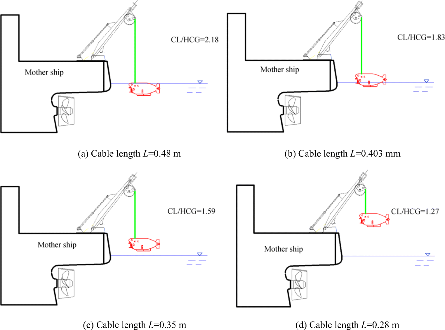 Figure 9 Four different lengths of cables. a Cable length L = 0.48 m. b Cable length L = 0.403 mm. c Cable length L = 0.35 m. d Cable length L = 0.28 m
CL/HCG was obtained by dimensionless treatment of the cable length and the height of the center-of-gravity. The motion response curves of the submersible for the head wave and beam wave with different cable lengths are shown in Figs. 10 and 11, respectively. In Fig. 10, $ \omega \sqrt{L/\mathrm{g}} $ = 1.33 corresponds to the maximum pitch angle of the ship, and in Fig. 11, $ \omega \sqrt{L/\mathrm{g}} $ = 2.11, which corresponds to the maximum roll angle of the ship.
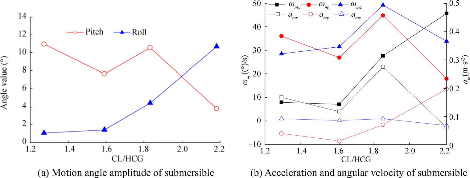 Figure 10 Motion response of submersible in head waves. a Motion angle amplitude of submersible. b Acceleration and angular velocity of submersible
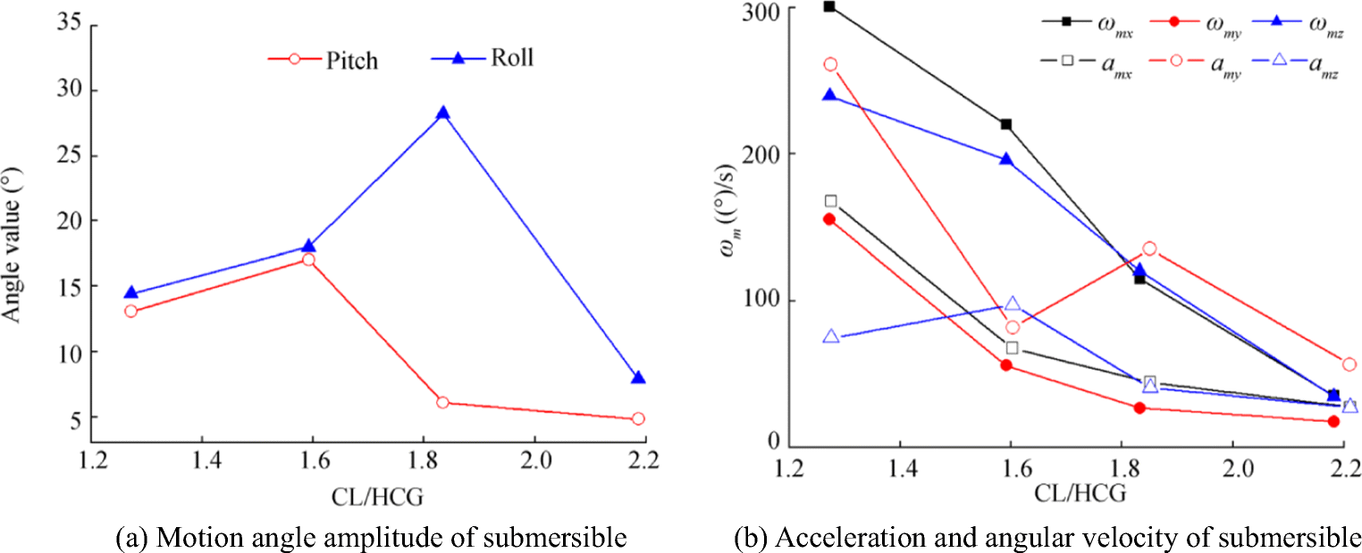 Figure 11 Motion response of submersible in beam waves. a Motion angle amplitude of submersible. b Acceleration and angular velocity of submersible
Some results can be obtained from Figs. 10 and 11; the movement amplitudes in the beam waves are much larger than those in the head waves, especially the angular velocities. In general, the longer the cable length is, the more violent the motion of submersible is in the head waves. However, these phenomena are exactly opposite in the head waves. Therefore, it is better to reduce the time of launching and recovering as far as possible, especially when the vessel is submerged near the water surface in the head waves. For the beam waves, reducing the docking time for submersible and swash frame is recommended. The submersible swung with a large magnitude relative to the ship as the ship model rolled violently in the beam waves and the swing angle amplitude could reach ± 25°. By contrast, this swing angle amplitude was no more than ± 10° when the ship model was in the head waves. Thus, to enhance the security of the submersible, the mother ship should be in the head waves when it launches or recovers the submersible.
3.3 Effect of Hoisting Submersible to Mother Ship
The experiments also measured the motion response of the ship model when it hoisted the submersible, and the results were compared with those of the mother ship without the submersible. To analyze the influence of the hoisting submersible on the motion response of the mother ship, we selected $ \omega \sqrt{L/\mathrm{g}} $ = 1.33 in the head waves and $ \omega \sqrt{L/\mathrm{g}} $ = 2.11 in the beam waves for analysis because they indicate the most intense working conditions. In the head waves, the motion responses of the ship model are shown in Table 3.
Table 3 Motion response of ship hoisting submersible in head wavesCable length M/H O/H β/φ Without submersible/mm 0.7583 0.7611 0.8766 280 0.7474 0.7444 0.8534 350 0.7333 0.7438 0.8550 403 0.7320 0.7157 0.8375 480 0.7469 0.7386 0.8516 According to Table 3, the heave, surge, and pitch amplitude of the ship fluctuate within six percentages due to the different length of the hoisting cable for the submersible. With the increase of cable length (280-403 mm), the movement amplitudes of the ship show a decreasing trend. When the cable length is selected as L = 480 mm, the submersible is in the state of floating in the water and the cable has no tension. In this state, the effect of the submersible on the ship movement is smaller than that in other cable states. Owing to the fluid resistance, the effect in this state is still larger than that without the submersible.
Similarly, the motion responses of the ship hoisting submersible in the beam waves are presented in Table 4.
Table 4 Motion response of ship hoisting submersible in beam wavesCable length/mm M/H N/H α/φ Without submersible 0.9844 0.8664 6.1865 280 1.0075 0.8394 4.1299 350 0.9711 0.8201 3.8653 403 0.9580 0.7930 5.7265 480 0.9843 0.8235 5.8593 According to Table 4, compared with the state of the ship without submersible, the heave and sway amplitude of the ship changes in the range of 2.5%-9% with different cable lengths and the amplitude of the ship decreases slightly with increasing cable length (280-403 mm). However, hoisting the submersible has an inhibiting effect on the rolling of the ship. Thus, the rolling angle decreases with the increase of cable length (280-350 mm). This phenomenon can be explained as the swing of submersible lags behind that of the mother ship, and this effect inhibits the ship movements. When the submersible is floating in water (L = 480 mm) and partly out of water (L = 403 mm), the water resistance direction on the submersible is opposite to its motion direction, which may weaken the inhibiting effect on the ship rolling motion.
3.4 Effect of Couple Motion on Cable Load
ADAMS software was used to simulate the launch and recovery of the HOV in the head and beam waves and to simulate the condition of the fixed cable length and 0.1 m/s hoisting speed. Figure 12 shows the simulation process.
 Figure 12 Numerical simulation couple motion
Figures 13(a) and 7(b) show the results of the numerical simulations under the heading and beam waves, where T represents the gravity of HOV, Tav = 0 is the tension when the velocity of the cable is 0, and Tav = 0.1 is the tension when the velocity of the cable is 0.1 m/s. According to Figs. 13 (a) and (b), the added tension forces in the beam waves are much larger than those in the head waves, especially the angular velocities. The added tension becomes smaller with the increase of $ \omega \sqrt{L/\mathrm{g}} $ in the head waves. When $ \omega \sqrt{L/\mathrm{g}} $ ≤ 2.5, the cable recovery leads the increase of added tension. When $ \omega \sqrt{L/\mathrm{g}} $ > 2.5, the cable recovery velocity causes added tension to increase. These results prove that the HOV recovery should not be conducted in the beam waves.
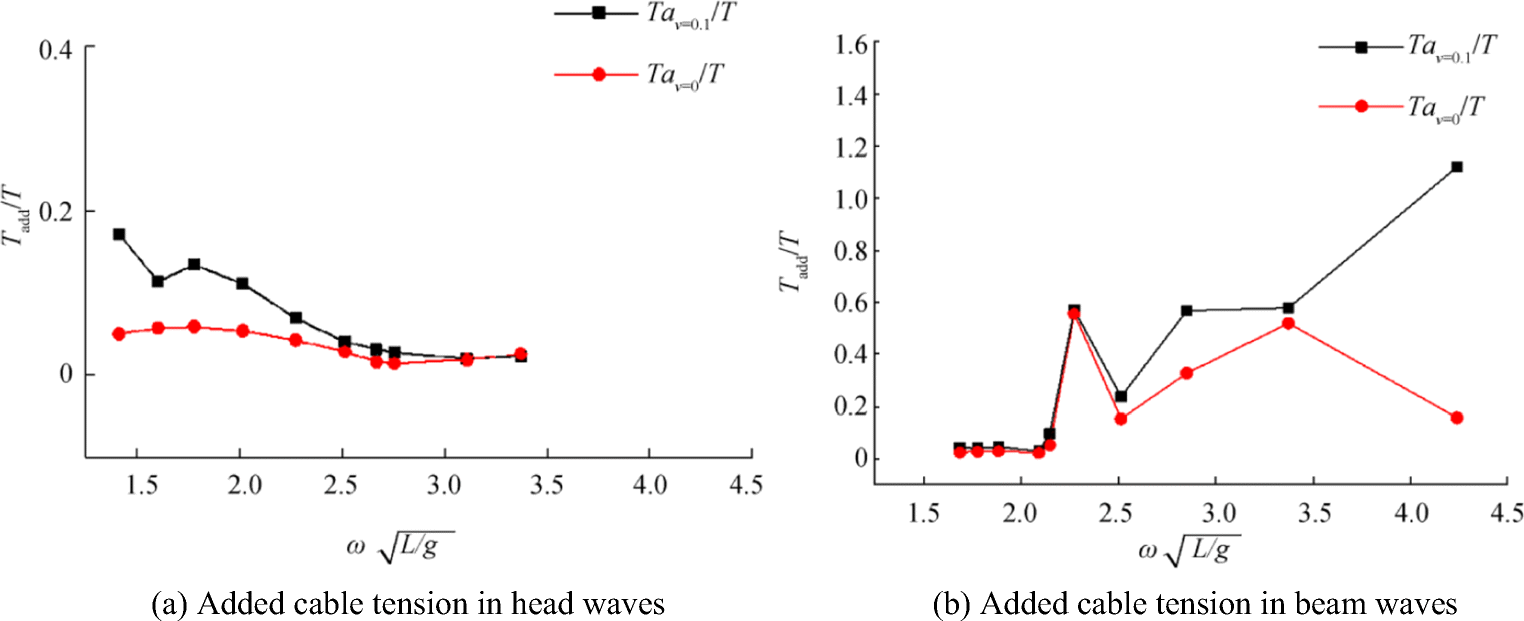 Figure 13 Added cable tension in head and beam waves. a Added cable tension in head waves. b Added cable tension in beam waves
4 Conclusion
In this study, we designed a model of a submersible and mother ship with LRS. We also studied the motion responses through experiments, where the submersible launched and recovered by the mother ship are implemented in waves. Based on the analysis of the experimental results, the following conclusions are drawn:
1) The HOV launching and recovery operation is greatly influenced by the wave direction and wave frequency. The operation of launching and recovery in the head waves, where the response is less than that in the beam waves, is recommended. When the wave length is similar to the vessel length at approximately $ \omega \sqrt{L/\mathrm{g}} $ = 2.7, the most dangerous situation occurs as the tension force increases to the maximum value at this time. When $ \omega \sqrt{L/\mathrm{g}} $ changes from 1.73 to 2.21, the wave length corresponds to two times the ship length, and the mother ship's pitch RAO does not change considerably and the hoisting point changes rapidly. Thus, avoiding operations above wave frequency is essential.
2) The length of the hoisting wire and submerged state of the HOV affect the dynamic response of the HOV. Thus, the operator should return the hoisting wire rapidly when the HOV is lifted out of the wave. When the HOV floats on the sea surface, the hoisting wire should be longer than the motion response of the HOV.
3) The hoisting HOV has an inhibiting effect on the rolling motion of the mother ship in the beam waves but has no effect on the swaying and heaving motions of the ship. Meanwhile, the hoisting submersible has no obvious effect on reducing the pitching, surging, and heaving motions of the ship in the head waves.
Open Access This article is distributed under the terms of the Creative Commons Attribution 4.0 International Li cense (http://creativecommons.org/licenses/by/4.0/), which permits unrestricted use, distribution, and reproduction in any medium, provided you give appropriate credit to the original author(s) and the source, provide a link to the Creative Commons license, and indicate if changes were made. -
Figure 1 HOV model. a Upper parts of HOV model. b Lower parts of HOV model
Figure 2 LRS. a 3D model: 1, mother ship; 2, frame base; 3, hydraulic cylinder; 4, spring set; 5, cable; 6, A-frame; 7, hoist point; 8, tension sensor; 9, submersible; 10, acceleration sensor. b Design and sensor position set
Figure 3 Experimental towing tank and trailer
Figure 4 Flap-type wave maker
Figure 5 Motion response experiments of ship model in head and beam waves. a Motion response experiments of ship model in head waves. b Motion response experiments of ship model in beam waves
Figure 6 Motion response experiments on ship launching and recovering HOV in head and beam waves. a Motion response experiments in head waves. b Motion response experiments in beam waves
Figure 7 Motion response curves in head waves. a Motion response of ship model. b Motion response of hoisting point
Figure 8 Motion response curves in beam waves. a Motion response of ship model. b Motion response of hoisting point. c Time history curve of ship model motion
Figure 9 Four different lengths of cables. a Cable length L = 0.48 m. b Cable length L = 0.403 mm. c Cable length L = 0.35 m. d Cable length L = 0.28 m
Figure 10 Motion response of submersible in head waves. a Motion angle amplitude of submersible. b Acceleration and angular velocity of submersible
Figure 11 Motion response of submersible in beam waves. a Motion angle amplitude of submersible. b Acceleration and angular velocity of submersible
Figure 12 Numerical simulation couple motion
Figure 13 Added cable tension in head and beam waves. a Added cable tension in head waves. b Added cable tension in beam waves
Table 1 Parameters of mother ship and its model
Parameters Mother ship Model Ship length (m) 100 2.86 Design waterline length (m) 95 2.71 Molded breadth (m) 18 0.51 Molded depth (m) 8 0.23 Designed draft (m) 5 0.14 Designed displacement (N) 39000 9.10 Height of center-of-gravity (m) 7.688 0.22 Table 2 Parameters of HOV and its model
Parameters HOV Model Submersible length (mm) 7000 200 Submersible breadth (mm) 2700 77 Submersible height (mm) 2700 77 Draft of floating state (mm) 2350 67 Full load weight (N) 148000 3.47 Table 3 Motion response of ship hoisting submersible in head waves
Cable length M/H O/H β/φ Without submersible/mm 0.7583 0.7611 0.8766 280 0.7474 0.7444 0.8534 350 0.7333 0.7438 0.8550 403 0.7320 0.7157 0.8375 480 0.7469 0.7386 0.8516 Table 4 Motion response of ship hoisting submersible in beam waves
Cable length/mm M/H N/H α/φ Without submersible 0.9844 0.8664 6.1865 280 1.0075 0.8394 4.1299 350 0.9711 0.8201 3.8653 403 0.9580 0.7930 5.7265 480 0.9843 0.8235 5.8593 -
Cha JH, Roh MI, Lee KY (2010) Dynamic response simulation of a heavy cargo suspended by a floating crane based on multibody system dynamics. Ocean Eng 37(14): 1273-1291. https://doi.org/10.1016/j.oceaneng.2010.06.008 Cui WC, Feng L, Zhen HU, Min Z, Wei G, Liu CG (2012) 7000 m sea trials test of the deep manned submersible "JIAOLONG". Journal of Ship Mechanics 16(10): 1131-1143. https://doi.org/10.3969/j.issn.1007-7294.2012.10.005 Dong L, Hui XU, Gao W, Luo HB (2012) Numerical simulation and experimental comparison about water depth's influences to moored floating crane ship. Ocean Eng 30(4): 125-130. https://doi.org/10.16483/j.issn.1005-9865.2012.04.009 Hu Z, Wang L, Ye C, He Z (2016) Research of acoustic survey devices applied on deepsea vehicles. IEEE/OES China Ocean Acoustics (COA), Harbin. https://doi.org/10.1109/COA.2016.7535702 Jin B, Zhu KQ, Zhang TY (2015) Dynamic simulation analysis of floating crane system in regular waves. J Waterw Harbor 36(5): 398-403. 1005-8443(2015)05-0398-06 Jin Y, Wan B, Liu D, Peng Y, Guo Y (2016) Dynamic analysis of launch & recovery system of seafloor drill under irregular waves. Ocean Eng 117(supplement C): 321-331. https://doi.org/10.1016/j.oceaneng.2016.03.056 Lee KY (2016) Consideration of launch and recovery systems for operation of underwater robot from manned platform. J Ocean Eng Technol 30(2): 141-149. https://doi.org/10.5574/KSOE.2016.30.2.141 Liu P, Su YM, Liao YL (2016) Numerical and experimental studies on the propulsion performance of a wave glide propulsor. China Ocean Eng 30(3): 393-406. https://doi.org/10.1007/s13344-016-0026-6 Liu FS, Chen JF, Qin HD (2017) Frequency response estimation of floating structures by representation of retardation functions with complex exponentials. Mar Struct 54: 144-166. https://doi.org/10.1016/j.marstruc.2017.04.001 Nam BW, Kim NW, Hong SY (2017) Experimental and numerical study on coupled motion responses of a floating crane vessel and a lifted subsea manifold in deep water. Int J Naval Architect Ocean Eng 9(5): 552-567. https://doi.org/10.1016/j.ijnaoe.2017.01.002 Ren HL, Wang XL, Hu YJ, Li CG (2007) Dynamic response simulation of lifting load system of ship-mounted cranes. J Syst Simul 19(12): 2665-2668. https://doi.org/10.3969/j.issn.1004-731X.2007.12.008 Sarda EI, Dhanak MR (2017) A USV-based automated launch and recovery system for AUVs. IEEE J Ocean Eng 42(1): 37-55. https://doi.org/10.1109/JOE.2016.2554679 Vedachalam N, Ramadass GA, Atmanand MA (2014) Review of technological advancements and HSE-based safety model for deep-water human occupied vehicles. Mar Technol Soc J 48(3): 25-42. https://doi.org/10.4031/MTSJ.48.3.7 Wang XL, You XY, Hu YJ (2010) Cargo pendulation analysis of moored crane ship under regular waves. China Mech Eng 21(9): 1077-1082 Xu X, Li X, Yang JM (2014) Numerical and experimental analysis for lifting of a semi-submersible crane vessel. J Ship Mech 18(7): 799-808. https://doi.org/10.3969/j.issn.1007-7294.2014.07.009 Zhang HL, Deng ZY, Luo YG (2012) Development actuality of submarine launch and recovery system. Ship Sci Technol 34(4): 3-6, 46. https://doi.org/10.3404/j.issn.1672-7649.2012.04.001