


 , , ,
, , ,
2. Department of Mechanical and Aerospace Engineering, Malek Ashtar University of Technology, Shahinshahr, Isfahan 83145/115, Iran
3. Department of Marine Science and Ocean Engineering, Malek Ashtar University of Technology, Shahinshahr, Isfahan 83145/115, Iran
4. Hydrodynamic Department, National University of Shipbuilding (NUOS), Nikolaev 35968/241, Ukraine
1 Introduction
Submarines in surface motion, behave like surface ship vessels. In this condition the majority of submarine displacement volume is below the water free surface, so resistance force in surface condition motion of submarine is higher than ship. On the other h and , a submarine in surface motion experiences wave making resistance and phenomena’s and flow around it are different from its submerged motion condition. Wave making resistance is caused by kinetic energy of wave. Therefore, the hydrodynamic designers of submarine vehicles strive to propose the optimum shape with the smallest amount of resistance in underwater and free surface movements. Although the submarines designed with most emphasis on their submerged performance, they have to operate on the surface for different missions. For example, battery charging and sometimes lengthy transit passages from base to its diving area(Roy and Rydill, 1994).
Major forces acting on a submarine are skin friction drag and residual resistance. Skin friction drag is created by viscous shear drag and residual resistance drag caused due to wave making and form resistance(Bertram, 2000). For a fixed displacement volume, one idea is to reduce the wave making resistance which is the biggest part of residual resistance in free surface motion to obtain a reasonable speed.
Previous studies showed that for the deeply submerged condition, drag is associated with the viscosity of the water and form drag(Roy and Rydill, 1994). Different shapes of underwater vehicles were considered in the literature. Ellipsoid shape for submarine hull is suitable for deep submerged condition. However, this shape is inappropriate for free surface condition, where waves with high altitude are generated in the bow region. Sometimes these waves reach to sail and whole body tends to move under the surface. On the other h and , a flared and pointed bow is not a good c and idate for under water operation. Experimental, analytical and numerical methods were applied to explore the optimum shape of underwater vehicles in submerged as well as surface motion. A well-known method to study of submarine surface motion resistance is the towing tank test of its scaled model.
A wide variety of shape optimizations are studied for surface and underwater vehicle. Flow measurement around a model ship with propeller and rudder for the design of hull forms show better resistance and propulsive performance(Van and Kim, 2006; Zhang, 2012). The bow wave breaking and the viscous interaction of stern wave study by simulating the free-surface flows(Kwag, 2000) and shape optimization of bow bulbs with minimum wave-making resistance based on Rankine source method(Van and Kim, 2006)are examples of shape optimization studies. The optimum shape of submarine bow and behavior of flow on a model of underwater vehicle with tango bow shape was studied by Moonesun et al.(2013). In this study, experimental tests in towing tank was conducted and compared with computational fluid dynamics(CFD)results and experimental formulas. The result showed the accuracy of each of six methods in the calculation of submerged resistance of submarine and present and optimum resistance coefficient for a submarine. Optimum hull shape of an underwater vehicle moving near the surface was studied by Alvarez et al.(2009). Specifically, a first-order ranking panel method has been implemented to compute the wave resistance on a body of revolution moving close to the free surface. The total drag of the scaled model of the torpedo-like and resulting optimum shape was measured in towing tank. Measurements has shown a smaller resistance of the optimized shape in the range of the considered Froude number and more total drag in surface condition due to wave forced resistance. The experimental study on forces and moment on AUV hull form in the vertical plane at towing tank was done by Jagadeesh et al.(2009). The study was carried out at typical speeds of autonomous underwater vehicles(0.4-1.4 m/s)by varying pitch angles(0-15°). The hydrodynamic forces and moment are measured by an internally mounted multi-component strain gauge type balance. The measurements have also been used to validate results obtained from a CFD code that uses Reynolds Average Navier-Stokes equations. The study showed that the axial and normal force coefficients are increased by 18% and 195%. The drag, lift and pitching moment coefficients are increased by 90%, 182% and 297% on vehicle hull form at α = 15° and Rev = 3.86×10⁵.
Suman et al.(2010)designed and tested an ellipsoidal head to evaluate the functionality for improved hydrodynamic performance of an underwater vehicle. The designed vehicle having ellipsoidal heads of different major to minor axes ratio is fabricated and tested experimentally to validate the computational results. The result showed that the hydrodynamic performance of the vehicle can be improved with ellipsoidal profile head in submerged conditions. Numerical study on control effectiveness of a high-speed underwater vehicle with cruciform stern configuration using a computational fluid dynamics approach was done by Kim and Cho(2011). The calculation of the control derivatives of the underwater vehicle is validated by comparison with the experimental results of towing tank tests. The numerical results showed that the force derivatives of the vehicle are over predicted by about 5% and the moment derivatives of the vehicle are over-predicted by about 10%.
A modified Rankine source panel method was presented for solving a linearized free-surface flow problem with respect to the double body potential. The results showed that the Rankine source panel method could be an efficient tool in evaluating the flow field, wave pattern and wave resistance for various ship forms(Shahjada Tarafder et al. 2008). Results also showed that the calculated wave making resistance is in line with measured data. A new model for the simulation of spilling breaking waves in naval flows was presented. The model has been implemented in a finite-volume code developed for naval flows, and its performances have been validated against experimental data for a submerged profile, an S60 hull in drift motion, and the US Combatant DTMB 5415 model on a straight course. This prevents the simulation of breaking on the shoulder and stern waves, as observed in real ship flows. In order to assess the characteristics of the model in a three-dimensional context, the wave patterns around an S60 hull in drift motion and around a DTMB 5415 model on a straight course were considered. The locations and extensions of the breakers were correctly captured in both cases. The wave damping due to breaking is also well represented. However, its effects tend to overlap with potential numerical viscosity due to the grid stretching, resulting in an excessive damping far from the hull(Muscari and Di Mascio, 2004).Xie and Ye(2011)used non linear programming to optimize the hull form of displacement type deep-vee vessels with bulbous. The total resistance was chosen as target function. The offsets of ship form are the optimizing variables. The hull form displacement and variation range of offsets are used as restrictions. The effect of sailing pose was considered to calculate the total resistance and the wave-making resistance of which was obtained by using Michell’s integration. The number of chine line, which should be considered in the hull form optimization has significant influence on the resistance performance. An improved hull form which exhibited a reduction rate of 17.15% on wave making resistance, 9.52% on frictional resistance, and 12.56% on total resistance was obtained at given ship speed. It is applicable and reliable to adopt nonlinear programming for the hull optimization of displacement type deep-vee vessels.
In the current investigation, the hydrodynamic behavior of a submarine with two different bows using towing tank experiments is studied. The main objective is to find an appropriate bow shape reducing the residual resistance i.e., the minimum total resistance in free surface motion. The examination process is constrained for constant volume of the vehicle. Tango and st and ard bows are two types of submarines bows that have been compared in surface motion. Forces acting on the model and flow pattern specially waves near bow are reported and discussed. The formulation employed in this study is in accordance with st and ards presented by the ITTC method.
2 Equipments and experimental procedure2.1 Model setupExperiments were conducted in the towing tank which has 108m length, 3m width and 2.2m depth. The basin is equipped with a trolley that’s able to operate in 0.05-6m/s speed with ±0.02m/s accuracy. The trolley is moved by two 7.5kW electromotor. The trolley is controlled via a wireless system from the control room of the lab. The system is prepared with proper frequency encoder, i.e., 500 pulses in minutes, which decreases the uncertainty of measurements. A three degree of freedom dynamometer is used for force measurements. The dynamometer was calibrated by calibration weights(ITTC, 2002b). Data was recorded via an accurate data acquisition system. The dynamometer equipped with 100N load cells that has 1% uncertainty(ITTC, 2002d). An amplifier set is used to raise signals of load cells and to reduce the noise sensitivity of the system. All data are filtered to eliminate the undesirable accelerating parts of the motion data, primary and terminative motion of the trolley. The data presented in this paper for each point is an average of several towing tank runs. For each run, at least 750 samples in 15s were collected and ensemble averaged. Schematic of the model and the overall test set up is shown in Fig. 1.

|
| Fig.1 Model setup in the towing |
As indicated, the main purpose of the study was to explore the effect of bow shape on the hydrodynamic behavior, i.e., residual and total resistance of a submarine in surface motions. The experiment was conducted with a submarine model that was made by wood(ITTC, 2002a). For the bow effect study on total resistance, two bows with the same length are manufactured. Fig. 2 shows the profiles of the bows. Profile A and B are tango and st and ard bow shape, respectively. Table 1 provides a summary of the scale model characteristics.

|
| Fig.2 The Bows profiles; tango shape(A) and st and ard shape(B) |
| Characteristics | Quantity |
| Length/mm | 2110 |
| Maximum diameter/mm | 233 |
| Length of each bows/mm | 390 |
| Draft/mm | 183 |
| Mass/kg | 32 |
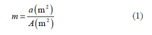
Furthermore, the model was connected to the dynamometer with a strut rigidly to restrict yaw, pitch and other uninvited motions. The forced transition(laminar to turbulence)was achieved by installation of trip strips on the model. Trip strips(10mm width)are installed on the bow at 5% of the overall length(Barlow et al., 1999). The trim angle of the model is adjusted to equal to zero for all tests. The models dimensions are selected considering the towing tank dimensions, speed of trolley and blockage effect. Blockage fraction for the model is 0.0053 that defined as:
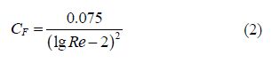
Total hull resistance is split up into friction, form and wave resistance components. The friction resistance is due to viscosity. The water far from the body is at rest. There is a sharp velocity profile near the body where fluids particles are attached to the model and are traveling with model velocity(Molland et al., 2011). In other words, a velocity gradient occurs in the boundary layer whilst persuades shear stresses that integrated over the wetted surface yield and lead to the friction resistance. Accurate computation of friction resistance may require an enormous computational effort. Friction resistance usually approximated by the drag generated as a result of a turbulent flow over a flat plate with the same wetted area and length of the body. The friction drag coefficient is given as(ITTC, 2002c):
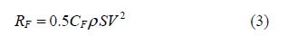
Using the results of the dynamometer in the towing tank, the total drag RT can be obtained. One may write:
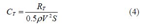
The residual drag is a significant parameter that typically used in hydrodynamic studies. The residual drag is defined as total resistance except for skin friction drag. Residual drag coefficient is considered as:

|
| Fig.3 Decomposition and classification of resistance in marine applications |
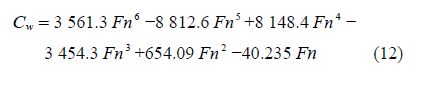
Wave resistance drag is the biggest components(up to 50%)of residual drag in surface motions at high Froude numbers. The height of wave given as:

|
| Fig.4 Variations of wave resistance coefficient versus Froude number |
An approximate formula for estimating the wave resistance is as below:
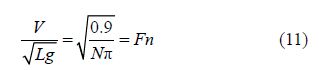
In order to investigate the effects of bow profile on hydrodynamic performance of the vehicle, total drag of the model is measured in a range of Froude numbers. Fig. 5 shows the variation of forces acting on the model versus Froude number for tango and st and ard bow profiles. The figure clearly shows that the total drag increases with Froude number. Fig. 5 shows that after critical Froude number(Fn=0.22), the trend of total drag decline with sharp slop, but before this Froude number, the trends of results progress such as a straight line and the variations are limited. Additionally, at low Froude number(0.098<Fn<0.22), difference between total drags caused by tango and st and ard bows are low(less than 1.08N). However at higher Froude numbers(0.22<Fn<0.3), the amount of total drag for st and ard bow is higher than that of tango bow. Maximum difference is 3.82N that observed at Fn of 0.3 where total drag of model with st and ard and tango bows are 16.08N and 19.91N respectively. At Fn=0.22, total resistance increases suddenly this means that critical Froude number of this vehicle is 0.22.

|
| Fig.5 Variation of total drags versus Froude number for tango and st and ard bows at trip conditions |
The total drag is the sum of friction drag and residual resistance. Fig. 6 show the variations of these types of drag as function of Froude number in a two graph for two bows. Fig. 6 show that all types of drags increase by Froude numbers. By inspection on the Figure, one can find that in Fn=0.22, there is a rapid augmentation in the total resistance. In low Froude numbers, friction drag is main part of the total drag. The result shows that for the model with tango bow at Fn=0.098, the residual resistance is 4 percent of total resistance. But for model with st and ard bow at the same Froude number, residual resistance is 33 percent of total drag. In this Froude number and for both bows, friction resistance is the biggest component of submarine total drag. By increasing Froude number to 0.197, residual resistance to total resistance ratio for tango and st and ard bows is 52% and 62% respectively. In Froude number between 0.3 to 0.325 residual resistances is major component of total drag for two bows.

|
| Fig.6 Variations of total, residual and friction drags as function of Froude number in a two graph for st and ard bow and tango bow |
On the other h and , the friction drag is not a strong function of Froude number for two cases. The friction drag depends on model dimensions and its wetted area. The length of the model and its wetted surface for the tango and st and ard bows are the same. Thus, the friction drag coefficients for two types of bows are nearly the same. Using measured data of total and calculated friction drag it is possible to find residual drag. Fig. 7 shows the variations of residual resistance coefficient against Froude number for two bows. The findings show that the quantity of the residual resistance coefficient of st and ard bow is more than tango shape. It is evident that there are many humps showing undesirable interactions and hallows points mentioned to the desirable interaction between bow and stern waves on the graph. One may conclude that residual resistance coefficient depends on shape of the submarine bow robustly.

|
| Fig.7 Variation of residual resistance coefficient with Froude number for two cases |
Fig. 8 shows variation of total, residual and friction resistance coefficients as a function of Froude number for two bows. The graph shows that the friction coefficient for two bows is the same. Other coefficients for st and ard bow are bigger than the tango bow, leading to higher total resistance for submarine with st and ard bow. Hump and hollow points for two bows are the same which shows that the hump and hollow points don’t depend on bow shape and depend on model length. According to the graph, Frictional resistance coefficient over range of the study is limited. But the residual resistance coefficient for two bows increases by Froude number. At Fn=0.22, residual resistance coefficient behaves like total resistance and has a sharp increase around this critical Froude number.

|
| Fig.8 Variations of hydrodynamic coefficients resistance by Froude number |
Investigation of flow pattern is a significant method for fluid studies. The ability to see flow patterns around an underwater vehicle under experimental investigations often gives insight into the design and optimization process. Here, the investigation of flow experiments is performed to realize the fluid physics on and around the model with different bows. Fig. 9 shows the wave product by both bow shapes at different velocities. All patterns are obtained by a high resolution camera fixed on the trolley. Fig. 10 shows the waves made by bows at the bow area of the model extended from wave crest due to high pressure stations.

|
| Fig.9 Flow investigations of waves made by tango and st and ard bows in around the bow body in different Froude numbers |
The waves in aft and forward portion of shoulder are involved in low pressure stations and extended from the wave’s depth. The height of waves is depended on values of velocities and increases for higher velocities. It is evident that at Fn=0.099 the height of waves are very similar for both bows.
For the tango bow, with an increase in the Froude number to 0.248, the first wave crest appears at the tip of the bow where the distance between the first crest to the next crest is nearly equal to the length of the bow. At higher Froude number, the wave height from the bow and the distance between the initial crest to the next, is more than that of lower Froude numbers. Further, at Fn=0.274, the waves will be collected on the top of the submarine bow. In higher Froude number(0.299 and 0.325)the water covers a part of the bow. Finally, in Fn=1.59 the water covers all of bow and some part of deck.
Similar results for the st and ard bow for Fn=0.099 to Fn=1.59 are indicated in Fig. 9. One can find that the physics are almost the same as the tango case but the distance between the two crests is less than the tango bow and interferences of the waves are dissimilar.
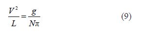
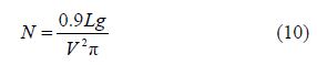
In order to investigate the effect of waves on hydrodynamic performance of the vehicle consider N, semi period number(Eq.(9)). It is seen that for N=1, the bow wave started with crest and extended to wave depth of stern that can produce an undesired interference and increases the amount of wave resistance due to amplifying a low pressure region. A different phenomenon occurs for N=2. In this case, the waves move to the stern with the same behavior, i.e. with the crest of the wave. In other words, the crest and the depth of the wave are neutralized or weakened in the stern due to a preferred interference. Therefore, the wave resistance may slightly change. One may conclude that the wave resistance will increase for odd values of N where it is almost fixed for even counterparts. The variations in the local curvatures show the interferences between the bow and stern waves in Fig. 10.

|
| Fig.10 The trajectories of the waves from bow to stern of the model with the both types of bows at different velocities |
If one can to cancel out these interferences, the waves follow a parabolic route without any local changing. Moreover, the resistance increases with the raise of velocity. The trajectories of the waves from bow to stern of the model with both types of bows at different velocities are shown in Fig. 8.
The results showed that the tango shape bow has the main effect on the wave breakage and decreases the resistance of the model more than the other bow shape. Also, for higher velocities, the height and length of the waves will increase. The profiles of bow and the Froude number have a significant role in the resistance of the model. Looking at the results, the tango shape bow creates desirable behavior for waves and reduces the resistance relatively to st and ard bow at the same Froude number. One may conclude that there are two reasons for resistance reduction due to decrease in the height of the wave. Firstly, the reduction of the wave height can decrease wave making resistance. Secondary, wave height reduction can also prevent the production of wave in critical conditions and undesirable interactions.
Fig. 11 shows variations of portion of the wave making resistance to the total resistance for the model with different types of bows. The results clearly showed that for lower velocities, there is a significant difference of wave resistance between tango and st and ard shapes of bows. However, at higher velocities this difference is less and is related to the length and the displacement volume of the submarine. The results showed that in low and middle Froude number(Fn=0.098-0.3), the height of wave caused by the tango bow is smaller than the st and ard bow. Therefore, the tango bow is more suitable for submarine in free surface motions.

|
| Fig.11 Variations of the portion of the wave making resistance to the total resistance for the model |
Experiments were performed to study the behavior of flow around a model of submarine with two types of bow shapes. The two types of bow shapes consisted of tango and st and ard bows in free surface tests. The resistance components for different Froude numbers were considered. Finally, flow visualizations of wave fields around bows are done and wave filed around two bows are compared. The Froude numbers were varied between 0.099 and 0.349. The trim angle of the model is adjusted equal to zero for all Froude numbers. Blockage fraction for the model is fixed to 0.005 3. The following conclusions are obtained in this investigation:
1)The residual resistance of the st and ard bow is higher than the tango bow in surface motion that caused more total resistance for the submarine. However, in high Froude, bow shape effect decreases and the total resistance depends on submarine's length and displacement.
2)The results showed that the role of residual resistance is over 80 percent of the total drag in larger Froude numbers where the variations of the friction drag with Froude number are slightly increased. Furthermore, the length of the model and wetted surface for the tango and st and ard bows are the same. Thus, the amount of friction drag coefficients for two types of bows is closely near.
3)The patterns of flow from visualization showed that the waves made by bows at bow and stern areas of the model extended from wave crest due to high pressure stations. While, the waves in aft and forward portion of shoulder are involved in low pressure stations and extended from waves depth. The height of waves is depended on values of velocities and increases for higher velocities. Also, for the st and ard bow, the distance between two crests is less than the tango bow and interferences of the waves are dissimilar.
4)The profiles of the bow and the Froude number played a significant role in the resistance of the model. Here, the tango shape bow created desirable behavior for waves and caused the least resistance relatively to st and ard bow at the same Froude number.
Nomenclatures
| A | Cross section area of towing tank(m2) |
| a | Cross section area of model(m2) |
| CF | Friction resistance coefficient |
| CT | Total resistance coefficient |
| Cw | wave resistance coefficient |
| Cvp | Viscous resistance coefficient |
| CR | Residual resistance coefficient |
| h | Combined wave height(m) |
| ha | Stern(aft)wave height(m) |
| hf | Bow(fore)wave height |
| L | Length in Froude number(m) |
| LOA | Length overall(maximum length)(m) |
| LBP | Length between perpendiculars(m) |
| LWL | Level waterline length |
| LCP | Length of center of pressure |
| N | Semi period number |
| R | Resistance or drag(N) |
| Re | Reynolds number |
| S | Wetted surface area(m2) |
| V | Speed of model(m/s) |
| λ | Wave length(m) |
| ρ | Water density(kg/m3) |
| Alvarez A, Bertram V, Gualdesi V (2009). Hull hydrodynamic optimization of autonomous underwater vehicles operating at snorkeling depth. Jordan Journal of Ocean Engineering, 36(1), 105-112. DOI: 10.1016/j.oceaneng.2008.08.006 |
| Barlow JB, Rae WH, Pope A (1999). Low-speed wind tunnel testing. 3rd edition. John Wiley & Sons, New York, USA, 609-649. |
| Bertram V (2000). Practical ship hydrodynamics. 1st edition. Butterworth-Heinemann, Kidlington, Oxford, UK, 68-117. |
| ITTC (2002a). Recommended procedures and guidelines—Model manufacture ship models. Proceedings of the 23rd International Towing Tank Conference, Venice, Italy, 7.5-01-01-01. |
| ITTC (2002b). Recommended procedures and guidelines—Sample work instructions calibration of load cells. Proceedings of the 23rd International Towing Tank Conference, Venice, Italy, 7.6-02-09. |
| ITTC (2002c).Recommended procedures and guidelines—Testing and extrapolation methods resistance: Resistance test. Proceedings of the 23rd International Towing Tank Conference, Venice, Italy, 7.5-02-02-01. |
| ITTC (2002d). Recommended procedures and guidelines—Testing and extrapolation methods resistance: Uncertainty analysis, example for resistance test. Proceedings of the 23rd International Towing Tank Conference, Venice, Italy, 7.5-02-02-02. |
| Jagadeesh P, Murali K, Idichandy VG (2009). Experimental investigation of hydrodynamic force coefficients over AUV hull form. Ocean Engineering, 36(1), 113-118. DOI: 10.1016/j.oceaneng.2008.11.008 |
| Kwag SH (2000). Bow wave breaking and viscous interaction of stern wave. Journal of Mechanical Science and Technology, 14(4), 448-455. DOI:10.1007/BF03186439 |
| Kim H, Cho H (2011). Numerical study on control derivatives of a high-speed underwater vehicle. Journal of Mechanical Science and Technology, 25(3), 759-765. DOI: 10.1007/s12206-011-0123-7 |
| Molland AF, Turnock SR, Hudson DR (2011). Ship resistance and propulsion. Cambridge University Press, New York, USA, 14-15. DOI: 10.1017/CBO9780511974113 |
| Moonesun M, Javadi M, Charmdooz P, Mikhailovich KU (2013). Evaluation of submarine model test in towing tank and comparison with CFD and experimental formula for fully submerged resistance. Indian Journal of Geo-Marine Sciences, 42(8), 1049-1056. |
| Muscari R, Di Mascio A (2004). Numerical modeling of breaking waves generated by a ship’s hull. Journal of Marine Science and Technology, 9(4), 158-170. DOI: 10.1007/s00773-004-0182-x |
| Roy B, Rydill L (1994). Concepts in submarine design. Cambridge University Press, London, UK, 104-124. |
| Shahjada Tarafder M, Suzuki K (2008). Numerical calculation of free-surface potential flow around a ship using the modified Rankine source panel method. Ocean Engineering, 35(5-6), 536-544. DOI: 10.1016/j.oceaneng.2007.11.04 |
| Suman KNS, Nageswara D, Das HN, Bhanu Kiran G (2010). Hydrodynamic performance evaluation of an ellipsoidal bow for a high speed under water vehicle. Jordan Journal of Mechanical and Industrial Engineering, 4(5), 641-652. |
| Van SH, Kim WJ (2006). Flow measurement around a model ship with propeller and rudder. Journal of Experiments in Fluids, 40(4), 533-545. DOI: 10.1007/s00348-005-0093-6 |
| Xie Yi, Ye Qing (2011). Hull form optimization of displacement type deep-vee vessels based on nonlinear programming. International Conference on Electrical and Control Engineering (ICECE), Yichang, China, 2266-2269. DOI: 10.1109/ICECENG.2011.6057745 |
| Zhang Baoji (2012). Shape optimization of bow bulbs with minimum wave-making resistance based on Rankine source method. Journal of Shanghai Jiaotong University, 17(1), 65-69. DOI: 10.1007/s12204-012-1239-3 |