 2014, Vol. 34


微生物燃料电池(Microbial fuel cell,MFC)能在降解有机污染物的同时产生电能,是一种新概念的废水处理方法(Logan et al., 2006a;2009).其原理为:阳极微生物(Exoelectrogens)厌氧氧化有机物获取电子,并将电子传递给阳极,再通过外电路传递给阴极电子受体(如氧气),同时伴随着质子由阳极到阴极的跨膜扩散(Logan et al., 2006b).
阳极微生物是影响MFC产电和降解性能的关键因素(Logan et al., 2008).宋天顺等(2012)以氨氮模拟废水为底物,分别以厌氧污泥和河底沉积物接种单室MFC阳极,研究发现,厌氧污泥接种的MFC的最大功率密度比沉积物接种的MFC大46.8%,但氨氮去除率却低3.8%.王慧勇等(2012)以模拟淀粉废水为底物,比较了分别接种生活污水和淀粉废水的MFC的性能,发现接种生活污水的MFC的最大功率密度比接种淀粉废水的高141.3%,氨氮去除率高2.7%. Li等(2013)以厨余浸出液为底物,发现以厌氧污泥为接种源的MFC的最大功率密度比以生活污水为接种源的MFC低1.8%,但VFA去除率高5.5%;PCR-DGGE分析发现二者的优势菌种存在显著差异.可见,在相同的MFC构型和环境条件下,接种源的微生物多样性与基质的特异性决定了MFC阳极微生物种群结构(Logan et al., 2006b;Pham et al., 2009),从而可能影响了MFC的产电和降解性能(Aelterman et al., 2006).
理论上,在易降解有机物-难降解有机物共基质体系中可驯化出能适应难降解有机物的菌种,基质的选择性压力(Logan et al., 2006b)会改变MFC阳极最初的微生物群落结构,富集出适应于代谢基质的优势菌群(Logan,2009; Yang et al., 2012).因此,在课题组前期研究的基础上(Sun et al., 2009a;2009b;Cao et al., 2010;Hou et al., 2011;Sun et al., 2011;2012),为明确接种源对MFC同步降解刚果红和产电的影响规律,本研究以葡萄糖-刚果红为共基质,以印染废水和生活污水处理系统中的污泥为接种源,探究两种接种源MFC同步降解刚果红和产电性能情况;并通过分析阳极生物膜电化学特性,分离并鉴定稳定运行下的MFC阳极优势菌种,阐明两种接种源MFC阳极优势菌种差异与降解刚果红和产电性能之间的关系,为基于接种源调控的MFC降解难降解有机物和产电提供借鉴.
2 材料与方法(Materials and methods) 2.1 试剂刚果红(C32H22N6O6S2Na2,分析纯),购于天津大茂化学试剂厂,使用前未经纯化处理.
2.2 反应器及其接种与运行采用好氧生物阴极双室MFC反应器(Hou et al., 2012),取广州市猎德污水处理厂和新洲工业园某印染废水处理站的厌氧污泥各10 mL,混合后分别作为MFC-M和MFC-I(M、I分别为Municipal、Industrial的缩写)阳极的接种源,接种浓度为2.0 g · L-1(以MLSS计).从驯化到稳定运行阶段,两个反应器阳极室培养液的组成均保持一致:刚果红300 mg · L-1、葡萄糖200 mg · L-1、PBS 50 mmol · L-1、微量元素溶液12.5 mL · L-1、维生素溶液12.5 mL · L-1(Lovley et al., 1988).阴极室培养液中不含刚果红和葡萄糖,其他成分与阳极培养液相同.运行过程中,阴极室维持60 mL · min-1的曝气量.采用批式运行,当输出电压值低于50 mV时更换培养液.
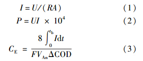
2.3 电化学性能表征电化学性能表征包括输出电压、库伦效率、功率密度、阴阳极极化曲线、循环伏安和电化学阻抗谱.MFC的输出电压由数据采集系统(Model 2700,Keithly Instruments,USA)每10 min自动采集1次.功率密度和阴阳极极化曲线采用变电阻的方法在MFC经过数周期运行稳定后进行同步测试,电极电势测定所用参比电极为饱和甘汞电极(SCE,0.242 V vs. 标准氢电极,上海雷磁).单位面积电流密度、功率密度及库伦效率的计算公式(Logan et al., 2006a)如下:
循环伏安(CV)和电化学阻抗谱(EIS)的测定均在Princeton 2273型电化学工作站上进行.当MFC开路电压达到稳定时,采用三电极体系进行测试,其中,工作电极为阳极,对电极为阴极,参比电极为饱和甘汞电极.循环伏安设置测试参数:扫描范围为-0.7~1.2 V,扫描速率为10 mV · s-1.电化学阻抗谱设置测试参数:频率范围为100 kHz~5 mHz,交流电压振幅为10 mV.
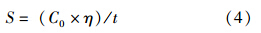
2.4 刚果红脱色性能表征刚果红(初始浓度300 mg · L-1)脱色率由紫外可见光分光光度计(DR5000,HACH,USA)在其最大波长(496 nm)下测定吸光度的减少值计算得到.在48 h内每隔6 h从MFC阳极中取样,稀释后测定吸光度.脱色率η可由下式计算得到:

脱色速率可由脱色率-时间曲线推算得出,由于脱色率随时间增加会先呈现线性上升,在一定时间后脱色速率明显降低、脱色率趋于稳定,为简化计算,平均脱色速率将直接采用近似线性部分的斜率进行计算,具体公式为
采用气相色谱-质谱联用(GC-MS,6890 N/5973 inert,Agilent Technologies,USA)对MFC周期末的阳极室降解液进行产物分析.样品处理及分析条件参考文献(廖梅东等,2010).
2.5 优势菌种的分离、纯化与鉴定采用营养琼脂培养基(Nutrient agar,NA)(pH=7.0)作为纯菌分离、纯化的基础培养基.在厌氧培养箱中,从稳定运行6个月以上的MFC-I和MFC-M的阳极生物膜上刮下少许,用无菌去离子水稀释到10-6倍后涂布平板,在(30±1)℃下的NA培养基中培养48 h.用新鲜的无菌NA培养基进行重复转移和纯化,直到获得纯培养菌株.采用LB(Luria-Bertani)培养基(pH=7.0)作为富集纯培养菌株的基础培养基.所用培养基均通过多次抽真空和通氮气以确保去除其中的氧气.菌种委托宝生物工程(大连)有限公司采用16S rRNA基因序列进行鉴定,使用BigDye Terminator V3.1 Cycle Sequencing Kit在ABI-PRISMTM 3730XL DNA测序仪上进行分析,在NCBI上的BLAST-n进行比对(www.ncbi.nlm.nih.gov/BLAST)分析核苷酸序列.
3 结果与讨论(Results and discussion) 3.1 两种接种源MFC的启动特点在外接1000 Ω电阻的条件下,两种接种源接种的MFC的输出电压随时间的变化如图 1所示.在接种后约800 h内(启动阶段),MFC-I和MFC-M的输出电压均表现出波动上升趋势,但MFC-I的输出电压略高于MFC-M.进入稳定运行阶段后,MFC-I和MFC-M的输出电压差别不大.
导致两种接种源MFC启动初期电压差别的原因在于刚果红对微生物的选择性压力.印染废水污泥中微生物长期经染料驯化,对刚果红的适应性强,来自刚果红的选择性压力较小;而生活污水污泥中的微生物首次接触刚果红,对刚果红的适应性较差,来自刚果红的选择性压力较大.但经过一定时间的驯化后,生活污水污泥中的微生物对刚果红的适应性增强,刚果红的选择性压力减弱,从而使两种接种源MFC稳定运行时的输出电压相当.
 |
| 图 1 两种接种源MFC输出电压-时间曲线 Fig. 1 Voltage output-time curves of MFC using different sludge as inoculums during setup and stable operation |
特定外电阻下的输出电压-时间曲线并不足以从整体描述MFC的产电性能.为探究不同外电阻下MFC-I和MFC-M产电性能的差异,采用变电阻法测试了两个反应器的功率密度和极化曲线.如图 2a所示,稳定运行阶段MFC-M的最大功率密度达到29.09 mW · m-2,比MFC-I高出2.11倍.阴、阳极极化曲线测定结果表明,二者功率密度差异是由阳极导致(图 2b).MFC-I阳极开路电势较MFC-M的高,且随着电流密度从0增加到0.015 mA · cm-2,MFC-I阳极电势较MFC-M的抬升幅度更高,表明在相同电流密度下,以印染废水污泥接种的MFC-I对刚果红-葡萄糖共基质的生物电化学氧化需要更大的驱动力(即能量需求更大),阳极过电势越大,这与功率密度测定的结果一致.选择运行1400 h后的3个稳定周期进行库伦效率的测定与计算,结果表明,MFC-M的库伦效率(即电子的回收率)较高,达31.89%;而MFC-I的库伦效率较低,为29.03%.
 |
| 图 2 稳定运行阶段MFC-I和MFC-M的功率密度(a)与阴、阳极极化曲线(b) Fig. 2 Power density(a) and polarization curves(b)of MFC-I and MFC-M during stable operation |
生活污水污泥接种的MFC-M产电性能更好,主要原因在于生活污水成分复杂,其污泥中微生物多样性丰富,包含的产电菌较多(Logan,2009;Yang et al., 2012);而印染废水污泥在染料的长期驯化下微生物种群相对单一,染料降解菌较多.此外,刚果红的降解与产电是电子竞争过程,相对于阳极,刚果红优先获得电子(Sun et al., 2012),MFC-I中较多的染料降解菌能竞争到更多的电子用于染料脱色,导致传递给阳极的电子减少,阳极极化明显.
3.3 两种接种源MFC阳极刚果红的降解速率和降解产物分析稳定运行阶段,MFC-I和MFC-M对刚果红的脱色率随时间变化如图 3所示.在运行周期初的12 h内,MFC-I(16.24 mg · L-1 · h-1)的平均脱色速率比MFC-M(13.50 mg · L-1 · h-1)高20.3%;12 h后脱色速率均明显降低,MFC-I(4.69 mg · L-1 · h-1)的平均脱色速率比MFC-M(4.10 mg · L-1 · h-1)高14.4%;在48 h内,MFC-I在任一时间点对刚果红的脱色率均比MFC-M高出4%~20%.这是由于印染废水污泥在染料的长期驯化下微生物多样性相对单一,其功能倾向于优先降解染料;结合产电性能比较,可从侧面验证了因刚果红降解与产电争夺电子导致的产电性能差异.48 h后,MFC-M和MFC-I对刚果红的脱色率均达到90%以上,说明在刚果红的长期驯化后,两种接种源对反应器的最终脱色率差异不大.
 |
| 图 3 稳定运行阶段两种接种源MFC对刚果红的脱色率-时间曲线 Fig. 3 Congo red decolorization efficiency-time curves of MFC-I and MFC-M during stable operation period |
两种接种源MFC阳极的刚果红脱色产物分析如图 4和图 5所示.从色谱峰的出峰时间和峰强度来看,MFC-I和MFC-M中刚果红脱色产物相同且浓度相当,主要有3种物质:2-氨基-1,4-萘醌(15.394 min)、2,2′-二氨基联苯(16.345 min)、4,4′-二氨基联苯(也称为联苯胺,17.861 min),这与孙健等的研究结果一致(Sun et al., 2012).这说明在刚果红-葡萄糖共基质环境下长期运行,两种接种源MFC对刚果红的降解产物和降解效率差异很小.
 |
| 图 4 稳定运行阶段周期末MFC-I(a)和MFC-M(b)阳极脱色产物气相色谱图 Fig. 4 GC of breakdown products in the anode of MFC-I(a) and MFC-M(b)determining during stable operation when the voltage was lower than 10 mV |
 |
| 图 5 稳定运行阶段周期末MFC-I和MFC-M阳极脱色产物质谱图(a.2-氨基-1,4-萘醌,b.2,2′-二氨基联苯,c.联苯胺) Fig. 5 MS of breakdown products 2-amino-1,4-naphthoquinone(a),2,2′-diaminodiphenyl(b), and benzidine(c)in the anode of MFC-I and MFC-M determining during stable operation when the voltage was lower than 10 mV |
CV被广泛用于研究MFC中细菌与电极表面的电化学交互作用机制(Rabaey et al., 2004;2005;Marsili et al., 2008).为了探究长期运行下,两种接种源MFC阳极生物膜与电极表面之间的电化学反应特性差异,对稳定运行阶段最大输出电压时和周期末(电压低于10 mV,基质几乎消耗完全)的MFC阳极进行了CV扫描.
如图 6a所示,最大输出电压下,MFC-I和MFC-M阳极的CV中均呈现出一对明显的氧化还原峰,分别为-0.41 V的氧化峰和0.52 V的还原峰(MFC-M),以及为-0.31 V的氧化峰和0.66 V的还原峰(MFC-I),但MFC-I氧化还原峰的位置均比MFC-M有些许偏移.这说明二者阳极表面发生氧化还原化学反应的物质不同,可能是两种接种源生物膜中微生物种群的差异所致(Marsili et al., 2008).同时,由图 6a可看出,MFC-M的氧化还原峰面积及峰高均明显大于MFC-I,说明MFC-M生物膜具有更高的电化学活性(Carmona-Martinez et al., 2011).由图 6b可以看出,与最大电压下(图 6a)的CV图相比,周期末CV图的氧化还原峰的峰高明显减小,这是共基质耗尽的结果.此外,氧化还原特征峰发生了不同程度的偏移,参考Rabaey等(2004)的研究,推测是刚果红脱色产物在阳极表面进一步氧化降解所致.
 |
| 图 6 稳定运行阶段最大电压时(a)和周期末(b)MFC-I和MFC-M阳极的循环伏安曲线 Fig. 6 Cyclic Voltammetry(CV)curves of the anodes of MFC-I and MFC-M determining during stable operation when(a)the maximum voltage was achieved and (b)the voltage was lower than 10 mV |
CV和GC-MS检测发现,在MFC-M和MFC-I 周期末CV图中,电压约为0.747 V时,均出现了峰电流约为16.3 mA的还原峰,其标准还原电位约为-0.201 V;结合GC-MS分析结果推测该峰为生物膜细菌产生的电子氧化还原介体之一的2-氨基—1,4-萘醌的特征峰(Rau et al., 2002;Fultz et al., 1982).2-氨基—1,4-萘醌的标准氧化还原电位高于细胞脱氢酶NDAH的氧化还原电位值(-0.320 V,Rau et al., 2002),但低于阳极电势(约为-0.100 V)和刚果红标准氧化还原电势(+0.102 V),说明2-氨基-1,4-萘醌可作为电子介体协助电子由细胞到阳极和刚果红分子的传递.其次,至今发现的醌类电子介体及其标准氧化还原电位已有2-氨基—3-羧基—1,4-萘醌(-0.071 V)、2-羟基—1,4-萘醌(-0.137 V)、1,2-萘醌(+0.135 V)、1,2-萘醌—4-磺酸(+0.217 V)(Yamazaki et al., 1999;Rau et al., 2002;Fultz et al., 1982;dos Santos et al., 2007),产物中拥有萘醌结构的2-氨基—1,4-萘醌的标准氧化还原电位约为-0.201 V,与其他醌类电子介体的标准氧化还原电位相近.最后,根据Nortemann等(1994)的研究发现,醌类电子介体是在Pseudomonas sp. BN6降解萘磺酸盐的过程中由微生物代谢得到的.刚果红与萘磺酸盐同样有醌类基团,且阳极优势菌种也以Pseudomonas sp.为主(见3.5节).由此推断,Pseudomonas sp.在代谢刚果红的过程中,使其断键生成2-氨基—1,4-萘醌,而2-氨基—1,4-萘醌作为电子介体可进一步促进氧化还原反应的进行.
采用EIS测定了两种接种源MFC阳极在最大电压时的阻抗,其能斯特曲线如图 7所示,阻抗分析见表 1.图 7中,曲线高频部分与X轴的交点对应值为欧姆阻抗Rs,从高频到低频得到半圆的拟合直径为极化阻抗Rct.由表 1可看出,MFC-I和MFC-M阳极的Rs和Rd均较小(约3~5 Ω),因此,阳极阻抗主要由表征电子传递速率的极化阻抗Rct导致.如图 7和表 1所示,在输出电压最大时,MFC-M阳极Rct比MFC-I阳极低38.0%,说明MFC-I的阳极电子供应不足或电子传递阻力较大,这与测得的阳极极化曲线一致.因为MFC-I中染料脱色菌较多,加速了刚果红脱色,消耗了大量来自共基质葡萄糖的电子,致使传递给阳极的电子急剧减少.
 |
| 图 7 图 7 最大电压时MFC-I和MFC-M阳极的能斯特曲线(Zre为阻抗Z的实部,Zim为阻抗Z的虚部) Fig. 7 Nyquist curves of the anode of MFC-I and MFC-M determining during stable operation when the maximum voltage was achieved |
| 表1 稳定运行阶段最大电压时MFC-I和MFC-M阳极的内阻分析 Table.1 Anodic inner resistance analysis of MFC-I and MFC-M determining during stable operation when the maximum voltage was achieved |
从MFC-M和MFC-I阳极各分离出3株纯菌,分别命名为M-P、M-P2、M-B和I-P、I-P2、I-A,绘制系统发育树如图 8所示.由图可知,MFC-M的优势菌为Pseudomonas sp.(M-P、M-P2)和Bacillus sp.(M-B);MFC-I的优势菌为Pseudomonas sp.(I-P、I-P2)和Aquamicrobium sp(I-A).其中,I-P和M-P、I-P2和M-P2、I-P和I-P2、M-P和M-P2、I-A和I-P、I-A和M-B、M-B和M-P的同源相似性分别为100%、99%、99%、99%、83%、81%、80%.可见,在一定的环境条件下,接种源微生物多样性与特征基质决定了MFC阳极优势菌种.
 |
| 图 8 MFC-I和MFC-M阳极生物膜上优势菌种的系统发育树 Fig. 8 Unrooted neighbor-joining phylogenetic tree of predominant microorganisms in the anodic biofilm of MFC-I and MFC-M |
在同步降解刚果红与产电MFC中的微生物一般可分为两种:①产电菌,主要负责传递电子到电极;②刚果红降解菌,主要负责降解刚果红及其脱色产物(Sun et al., 2012).Pseudomonas sp.和Bacillus sp.均为最常见的产电菌属.其中,Pseudomonas sp.能分泌电子介体(如绿脓菌素),加速电子由细胞表面到阳极表面的传递,并且这类生物型电子介体还可被其他细菌利用,进行种间电子传递,增大MFC输出功率(Rabaey et al., 2004,2005;Logan et al., 2009).而Bacillus sp.在MFC中主要借助溶解性电子介体传递电子(Nimje et al., 2009).同时,Pseudomonas sp.和Bacillus sp.也是常见的染料降解菌(Cervantes et al., 2011;Jain et al., 2012).故可以判断MFC-M在产电和刚果红降解方面的高效性能归功于同为产电菌和染料降解菌的优势菌种Pseudomonas sp.和Bacillus sp..从图 8中可以看出,在MFC-I中也分离出了与MFC-M中同源性较高的Pseudomonas sp..此外,关于Aquamicrobium sp.虽然在MFC领域中的应用虽然鲜有报道,但已发现其能够代谢杂环化合物噻吩-2-甲酸叔丁酯(Bambaue et al., 1998)、联苯和聚氯联苯(Chang et al., 2013),因此,极有可能具有降解刚果红的能力.
综上分析可以初步判断,两种接种源MFC阳极均存在产电菌和刚果红降解菌,但由于各优势菌属的刚果红降解与产电途径和能力的差异,从而导致了二者在同步降解刚果红与产电过程中功率密度、刚果红脱色速率和生物膜电化学活性的差异.
1)分别以印染废水污泥和生活污水污泥接种MFC,研究发现,接种源会影响MFC的产电性能.启动阶段,MFC-I的输出电压高于MFC-M;但稳定运行阶段,二者最大输出电压差别不大.稳定运行阶段MFC-M最大功率密度比MFC-I高2.11倍,阳极Rct比MFC-I低38.0%,生物膜电化学活性更强.
2)接种源同时会影响MFC对刚果红的脱色性能,但对刚果红的降解产物没有影响.MFC-I对刚果红的脱色速率比MFC-M高14.4%~20.3%,主要降解产物均为2-氨基—1,4-萘醌、2,2′-二氨基联苯、4,4′-二氨基联苯.
3)接种源还会导致MFC阳极优势菌种的差异.二者均存在Pseudomonas sp.,但MFC-M阳极还存在优势菌Bacillus sp.,而MFC-I的阳极还存在优势菌Aquamicrobium sp.
| [1] | Aelterman P, Rabaey K, Pham H T, et al. 2006.Continuous electricity generation at high voltages and currents using stacked microbial fuel cells[J].Environmental Science and Technology, 40: 3388-3394 |
| [2] | Bambauer A, Rainey F A, Stackebrandt E, et al. 1998.Characterization of Aquamicrobium defluvⅡ gen.nov., sp.nov., a thiophene-2-carboxylate-metabolizing bacterium from activated sludge[J].Archives of Microbiology, 169: 293-302 |
| [3] | Bond D R, Holmes D E, Tender L M, et al. 2002.Electrode-reducing microorganisms that harvest energy from marine sediments[J].Science, 295: 483-485 |
| [4] | Carmona-Martinez A A, Harnisch F, Fitzgerald L A, et al. 2011.Cyclic voltammetric analysis of the electron transfer of Shewanella oneidensis MR-1 and nanofilament and cytochrome knock-out mutants[J].Bioelectrochemistry, 81(2): 74-80 |
| [5] | Cao Y, Hu Y, Sun J, et al. 2010.Explore various co-substrates for simultaneous electricity generation and Congo red degradation in air-cathode single-chamber microbial fuel cell[J].Bioelectrochemistry, 79(1): 71-76 |
| [6] | Cervantes F J, dos Santos A B.2011.Reduction of azo dyes by anaerobic bacteria: microbiological and biochemical aspects[J].Reviews of Environmental Science & Biotechnology, 10: 125-137 |
| [7] | Chang Y C, Takada K, Choi D, et al. 2013.Isolation of biphenyl and polychlorinated biphenyl-degrading bacteria and their degradation pathway[J].Applied Biochemistry & Biotechnology, 170(2): 381-398 |
| [8] | De Schamphelaire L, Cabezas A, Marzorati M, et al. 2010.Microbial community analysis of anodes from sediment microbial fuel cells powered by rhizodeposits of living rice plants[J].Applied Environmental and Microbiololgy, 76(6): 2002-2008 |
| [9] | dos Santos A B, Cervantes F J, van Lier J B. 2007.Review paper on current technologies for decolourisation of textile wastewaters: perspectives for anaerobic biotechnology[J].Bioresource Technology, 98(12): 2369-2385 |
| [10] | Fatemi S, Ghoreyshi A A, Najafpour G, et al. 2012.Bioelectricity generation in mediator-less microbial fuel cell: Application of pure and mixed cultures[J].Iranica Journal of Energy and Environment, 3 (2):104-108 |
| [11] | Fultz M, Durst R.1982.Mediator compounds for the electrochemical study of biological redox system: a compilation[J].Analytica Chimica Acta, 140: 1-18 |
| [12] | Han J L, Wang C T, Hu Y C, et al. 2010.Exploring power generation of single-chamber microbial fuel cell using mixed and pure cultures[J].Journal of the Taiwan Institute of Chemical Engineers, 41(5): 606-611 |
| [13] | Hou B, Sun J, Hu Y Y, et al. 2011.Simultaneous Congo red decolorization and electricity generation in air-cathode single-chamber microbial fuel cell with different microfiltration, ultrafiltration and proton exchange membranes[J].Bioresource Technology, 102(6): 4433-4438 |
| [14] | Hou B, Hu Y, Sun J.2012.Performance and microbial diversity of microbial fuel cells coupled with different cathode types during simultaneous azo dye decolorization and electricity generation[J].Bioresource Technology, 111: 105-110 |
| [15] | 黄霞, 梁鹏, 曹效鑫, 等.2007.无介体微生物燃料电池的研究进展[J].中国给水排水, 23 (4): 1-6 |
| [16] | Jain K, Shah V, Chapla D, et al. 2012.Decolorization and degradation of azo dye-Reactive Violet 5R by an acclimatized indigenous bacterial mixed cultures-SB4 isolated from anthropogenic dye contaminated soil[J].Journal of Hazardous Materials, 213/214: 378-386 |
| [17] | Jung S, Regan J M.2007.Comparison of anode bacterial communities and performance in microbial fuel cells with different electron donors[J].Applied Microbiology and Biotechnology, 77 (2): 393-402 |
| [18] | Kim B H, Park H S, Kim H J, et al. 2004.Enrichment of microbial community generating electricity using a fuel-cell-type electrochemical cell[J].Applied Microbiology and Biotechnology, 63: 672-681 |
| [19] | Li X M, Cheng K Y, Selvam A, et al. 2013.Bioelectricity production from acidic food waste leachate using microbial fuel cells: Effect of microbial inocula[J].Process Biochemistry, 48: 283-288 |
| [20] | Li Z, Zhang X, Lin J, et al. 2010.Azo dye treatment with simultaneous electricity production in an anaerobic-aerobic sequential reactor and microbial fuel cell coupled system[J].Bioresource Technology, 101: 4440-4445 |
| [21] | 廖梅东, 杭义萍.2010.GC-MS与H PLC/DAD联用对纺织品中4-氨基偶氮苯的测定[J].分析测试学报, 29 (8): 846-849 |
| [22] | Logan B E.2008.Microbial Fuel Cells[M].New Jersey: Johns Wiley & Sons |
| [23] | Logan B E.2009.Exoelectrogenic bacteria that power microbial fuel cells[J].Nat Rev Microbiol, 7: 375-381 |
| [24] | Logan B E, Hamelers B, Rozendal R, et al. 2006a.Microbial fuel cells: methodology and technology[J].Environmental Science and Technology, 40(17): 5181-5192 |
| [25] | Logan B E, Regan J M.2006b.Electricity-producing bacterial communities in microbial fuel cells[J].Trends in Microbiology, 14(12): 512-518 |
| [26] | Lovley D R, Phillips E J P.1988.Novel mode of microbial energy metabolism: organism carbon oxidation coupled to dissimilatory reduction of iron and manganese[J].Applied and Environmental Microbiology, 54: 1472-1480 |
| [27] | Marsili E, Rollefson J, Baron D, et al. 2008.Microbial biofilm voltammetry: direct electrochemical characterization of catalytic electrode-attached biofilms[J].Applied and Environmental Microbiology, 74 (23): 7329-7337 |
| [28] | Min B, Logan B E.2004.Continuous electricity generation from domestic wastewater and organic substrates in a flat plate microbial fuel cell[J].Environmental Science and Technology, 38: 5809-5814 |
| [29] | Min B, Kim J R, Oh S E, et al. 2005.Electricity generation from swine wastewater using microbial fuel cells[J].Water Research, 39: 4961-4968 |
| [30] | Niessen J, Harnisch F, Rosenbaum M, et al. 2006.Heat treated soil as convenient and versatile source of bacterial communities for microbial electricity generation[J].Electrochemistry Communications, 8: 869-873 |
| [31] | Nimje V R, Chen C Y, Chen C C, et al. 2009.Stable and high energy generation by a strain of Bacillus subtilis in a microbial fuel cell[J].Journal of Power Sources, 190(2): 258-263 |
| [32] | Nimje V R, Chen C Y, Chen H R, et al. 2012.Comparative bioelectricity production from various wastewaters in microbial fuel cells using mixed cultures and a pure strain of Shewanella oneidensis[J].Bioresource Technology, 104: 315-323 |
| [33] | Nortemann B, Kuhm A E, Knackmuss H J, et al. 1994.Conversion of substituted naphthalenesulfonates by Pseudomonas sp.BN6[J].Archieves of Microbiology, 161: 320-327 |
| [34] | Patil S A, Surakasi V P, Koul S, et al. 2009.Electricity generation using chocolate industry wastewater and its treatment in activated sludge based microbial fuel cell and analysis of developed microbial community in the anode chamber[J].Bioresource Technology, 100(21): 5132-5139 |
| [35] | Pham T H, Boon N, Aelterman P, et al. 2008.Metabolites produced by Pseudomonas sp.enable a Gram positive bacterium to achieve extracellular electron transfer[J].Applied Microbiology and Biotechnology, 77: 1119-1129 |
| [36] | Pham T H, Aelterman P, Verstraete W.2009.Bioanode performance in bioelectrochemical systems: recent improvements and prospects[J].Trends in Biotechnology, 27(3): 168-178 |
| [37] | Rabaey K, Angenent L, Schröder U, et al. 2010.Bioelectrochemical Systems: From Extracellular Electron Transfer to Biotechnological Application[M].London: IWA |
| [38] | Rabaey K, Boon N, Hofte M, et al. 2005.Microbial phenazine production enhances electron transfer in biofuel cells[J].Environmental Science and Technology, 39 (9): 3401-3408 |
| [39] | Rabaey K, Boon N, Siciliano S, et al.2004.Biofuel cells select for microbial consortia that self-mediate electron transfer[J].Applied and Environmental Microbiology, 70 (9): 5373-5382 |
| [40] | Rabaey K, Lissens G, Siciliano S D, et al. 2003.A microbial fuel cell capable of converting glucose to electricity at high rate and efficiency[J].Biotechnology Letters, 25 (18):1531-1535 |
| [41] | Rau J, Knackmuss H J, Stolz A.2002.Effects of different quinoid redox mediators on the anaerobic reduction of azo dyes by bacteria[J].Environmental Science and Technology, 36: 1497-1504 |
| [42] | Reimers C E, Leonard M, Fertig S, et al.2001.Harvesting energy from the marine sediment-water interface[J].Environmental Science and Technology, 35: 192-195 |
| [43] | Ren Z, Ward T E, Regan J M.2007.Electricity production from cellulose in a microbial fuel cell using a defined binary culture[J].Environmental Science and Technology, 41 (31): 4781-4786 |
| [44] | Solanki K, Subramanian S, Basu S.2013.Microbial fuel cells for azo dye treatment with electricity generation: A Review[J].Bioresource Technology, 131: 564-571 |
| [45] | Song T S, Cai H Y, Yan Z S, et al. 2012.Various voltage productions by microbial fuel cells with sedimentary inocula taken from different sites in one freshwater lake[J].Bioresource Technology, 108: 68-75 |
| [46] | 宋天顺, 吴夏芫, 肖鹏, 等.2012.不同接种物对微生物燃料电池利用氨氮产电的影响[J].可再生能源, 30 (11): 110-113 |
| [47] | Sun M, Tong Z H, Sheng G P, et al. 2010.Microbial communities involved in electricity generation from sulfide oxidation in a microbial fuel cell[J].Biosensors and Bioelectronics, 26: 470-476 |
| [48] | Sun J, Hu Y Y, Bi Z, et al.2009a.Improved performance of air-cathode single-chamber microbial fuel cell for wastewater treatment using microfiltration membranes and multiple sludge inoculation[J].Journal of Power Sources, 187(2): 471-479 |
| [49] | Sun J, Hu Y Y, Bi Z, et al. 2009b.Simultaneous decolorization of azo dye and bioelectricity generation using a microfiltration membrane air-cathode single-chamber microbial fuel cell[J].Bioresource Technology, 100: 3185-3192 |
| [50] | Sun J, Hu Y Y, Hou B.2011.Electrochemical characteriztion of the bioanode during simultaneous azo dye decolorization and bioelectricity generation in an air-cathode single chambered microbial fuel cell[J].Electrochimica Acta, 56(19): 6874-6879 |
| [51] | Sun J, Li Y, Hu Y Y, et al. 2012.Understanding the degradation of Congo red and bacterial diversity in an air-cathode microbial fuel cell being evaluated for simultaneous azo dye removal from wastewater and bioelectricity generation[J].Applied Microbiology & Biotechnology, 97: 3711-3719 |
| [52] | Tender L M, Reimers C E, Stecher H A, et al. 2002.Harnessing microbially generated power on the seafloor[J].Nature Biotechnology, 20: 821-825 |
| [53] | Vázquez-Larios A L, Solorza-Feria O, Vázquez-Huerta G, et al. 2011.Effects of architectural changes and inoculum type on internal resistance of a microbial fuel cell designed for the treatment of leachates from the dark hydrogenogenic fermentation of organic solid wastes[J].International Journal of Hydrogen Energy, 36 (10): 6199-6209 |
| [54] | 王慧勇, 呼唤, 梁鹏.2012.不同来源菌群接种微生物燃料电池处理淀粉废水的研究[J].工业水处理, 32 (7): 60-63 |
| [55] | Yamazaki S, Kano K, Ikeda T, et al.1999.Role of 2-amino-3-carboxy-1, 4-naphtoquinone, a strong growth stimulator for bifidobacteria, as an electron transfer mediator for NAD(P)+ regeneration in Bifidobacterium longum[J].Biochimica et Biophysica Acta, 1428: 241-250 |
| [56] | Yang S, Du F, Liu H.2012.Characterization of mixed-culture biofilms established in microbial fuel cells[J].Biomass and Bioenergy, 46: 531-537 |