2. 中国科学院上海应用物理研究所 嘉定园区 上海 201800
2. Shanghai Institute of Applied Physics, Chinese Academy of Sciences, Jiading Campus, Shanghai 201800, China
钍基熔盐堆 (Thorium Molten Salt Reactor, TMSR) 作为先进的第四代核能堆型[1],采用高纯度氟盐(一回路:Li2BeF4,二回路:FLiNaK)作为冷却剂,系统设计温度超过650℃[2]。复合熔盐具有高工作温度、低回路压强、高体积热容、低化学活性等优点[3],作为传热和蓄热工质,也可实现与制氢、发电和蓄热系统的有机耦合[4],完成绿色能源的转化。如聚焦型太阳能热发电技术 (Concentrating Solar Power, CSP) Sunshot项目研究中指出:考虑太阳能集热发电系统的经济性,需要把熔盐介质温度提高到650℃以上[5]。另外太阳能热驱动生物质超临界水气化制氢系统中,根据生物质超临界水气化制氢部分、聚光部分和熔盐传热蓄热部分的工作原理,也得出以下结论:生物质反应系统氢气生成率与系统反应压力和反应温度有密切关系,反应压力越大,温度越高,则反应速度越快,气化率也越高。需要生物质气化反应温度为600-700℃,高温熔盐换热系统的介质温度大于700℃[6]。
美国圣地亚国家实验室熔盐试验回路 (Molten Salt Test Loop,MSTL) 上对585 ℃熔盐介质进行了压差法测流量的评估,结果表明由于压力计受环境影响波动较大 ( > 138.9kPa),不能满足流量测量的要求[7]。美国橡树岭国家实验室 (Oak Ridge National Laboratory, ORNL) 在1967年一篇介绍“未来熔盐堆仪控元件开发指导性报告”中特别指出:超声波流量计作为一种非接触式仪表,适于熔盐堆高温、高剂量大管径燃料盐流量测量[8],其流量测量准确度几乎不受被测流体温度、压力、粘度、密度等参数的影响[9]。目前市面上的超声波流量计限于材料或电子学耐温的原因最高可测到535℃,该研究通过波导改进使超声波流量计能够进行650℃以上熔盐流量测量,需要对其进行标定。
现有的液体流量标定方法和标定装置有标准容积法、标准质量法和标准体积管法[10]。标准容积法有较高的精度,但在标定大流量时制作精密的大型标准容器比较困难[11];标准质量法是以秤替代标准容器作为标准器,用秤量一定时间流入容器内的流量总体的方法来计算被测液体的流量,精度可达0.1%;标准流量计法使用经过标定的高精度流量计对现有的流量计进行标定,精度也在0.1%左右[12]。上述方法虽然在原理上对高温熔盐的标定适用,但是标定用的介质通常为油和水,生产针对高温熔盐介质的标准装置存在困难。
表 1展示了国内第四代堆自建的高温流量标定平台的参数,其中工作温度均不超过400℃,且测量介质具有良导电性,通常流量计采用电磁式流量计,而高温熔盐通常不是良导体,工作温度要达到700℃,此类装置也不适用[13-16]。
| 表 1 现有高温回路流量标定平台参数 Table 1 Existing high temperature flow calibration loop parameters |
TMSR项目设计了新的针对熔盐回路的高温流量计标定平台。新平台采用独特的气压驱动方式,相较于其他平台,该驱动方式节省大量制作成本,用盐量也大大降低。本文通过构建标定平台的物理模型,以验证其物理上的正确性和工程上的可行性。在构建的物理模型下,对各种控制方案进行了仿真,最终确定了装置的最优化参数和可行性方案,以达到整体目标:减少用盐量、用气量,降低系统误差、设备选型和整体控制难度。
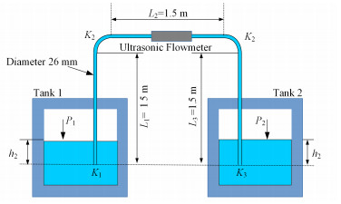
1 物理模型图 1为标定平台简化物理模型。假设熔盐在管道中稳定流动(标定平台也是为得到稳定流动的熔盐),由于熔盐为不可压缩的流体,在管道进口和出口可列出其流体伯努利方程:
| $\frac{{{P}_{1}}}{{{\rho }_{\operatorname{s}}}g}+\frac{{{v}^{2}}}{2g}\text{+}{{h}_{1}}=\frac{{{P}_{2}}}{{{\rho }_{\operatorname{s}}}g}+\frac{{{v}^{2}}}{2g}\text{+}{{h}_{2}}+\sum{f\frac{{{L}_{i}}{{v}^{2}}}{2dg}+}\frac{{{K}_{j}}{{v}^{2}}}{2g}$ | (1) |
|
图 1 标定平台简化物理模型 Figure 1 Simplified physical models for the calibration platform |
式中:ρs为熔盐的密度;g为重力常数;P1为罐1内的压力;P2为罐2内的压力;v为熔盐在管道内的流速;Li为直管i的长度;f为流体在直管内的摩擦系数;d为熔盐管道直径;Kj为进口、出口和弯管的形阻系数,反映了该处的压降效应。f、Kj主要与雷诺数有关。
将式 (1) 再化简为:
| $ \left( {{P}_{1}}-{{P}_{2}} \right)+{{\rho }_{\operatorname{s}}}g\left( {{h}_{1}}-{{h}_{2}} \right)=\sum{f\frac{{{L}_{i}}}{d}{{\rho }_{\operatorname{s}}}\frac{{{v}^{2}}}{2}\sum{{{K}_{j}}{{\rho }_{\operatorname{s}}}\frac{{{v}^{2}}}{2}}} $ |
令:
| $\Delta P=\left( {{P}_{1}}-{{P}_{2}} \right)+{{\rho }_{\text{s}}}g\left( {{h}_{1}}-{{h}_{2}} \right)$ | (2) |
| ${{\xi }_{\text{pipe}}}=\sum{f\frac{{{L}_{i}}}{d}\sum{{{K}_{j}}}}$ | (3) |
则流速v可以表示为:
| $v=\sqrt{\frac{2\Delta P}{\rho {{\xi }_{\text{pipe}}}}}$ | (4) |
这样熔盐的流量为:
| ${{Q}_{v}}=\frac{\text{ }\!\!\pi\!\!\text{ }{{d}^{2}}}{4}v=\frac{\text{ }\!\!\pi\!\!\text{ }{{d}^{2}}}{4}\sqrt{\frac{2\Delta P}{{{\rho }_{\text{s}}}{{\xi }_{\text{pipe}}}}}$ | (5) |
式中:
ΔP含两项:第一项
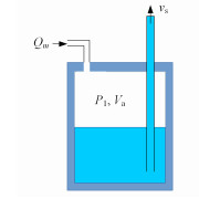
罐1的气压控制模型如图 2所示。
|
图 2 罐1的气压控制模型 Figure 2 Pressure control model for tank 1 |
假设在
| ${{P}_{1}}=\frac{RT}{M}\frac{m}{{{V}_{\text{a}}}}$ | (6) |
等式两边同时对时间t求导:
| $\frac{\operatorname{d}{{P}_{1}}}{\operatorname{d}t}=\frac{RT}{M}\frac{\operatorname{d}\left( \frac{m}{{{V}_{\operatorname{a}}}} \right)}{\operatorname{d}t}=\frac{RT}{M}\left( \frac{1}{{{V}_{\operatorname{a}}}}\frac{\operatorname{d}m}{\operatorname{d}t}-\frac{m}{V_{\operatorname{a}}^{2}}\frac{\operatorname{d}{{V}_{\text{a}}}}{\operatorname{d}t} \right)$ | (7) |
t时刻氩气的质量流量为Qm,则dt时间注入罐1的氩气质量dm为:
| $\text{d}m={{Q}_{m}}\text{d}t$ | (8) |
由于熔盐为不可压缩流体,t时刻熔盐从罐1流入连接管道的体积流量为
| $\text{d}{{V}_{\operatorname{a}}}={{v}_{\operatorname{s}}}\frac{\text{ }\!\!\pi\!\!\text{ }{{d}^{2}}}{4}\text{d}t$ | (9) |
将式 (8)、(9) 带入式 (7),得:
| $ \frac{\text{d}{{P}_{1}}}{\text{d}t}=\frac{RT}{M}\left( \frac{1}{{{V}_{\operatorname{a}}}}{{Q}_{m}}-{{v}_{\operatorname{s}}}\frac{\pi {{d}^{2}}}{4}\frac{m}{V_{\operatorname{a}}^{2}} \right) $ |
化简得到:
| $\frac{\text{d}{{P}_{1}}}{\text{d}t}=\frac{RT}{M}\frac{1}{{{V}_{\operatorname{a}}}}{{Q}_{m}}-\frac{\pi {{d}^{2}}}{4}\frac{{{P}_{1}}}{{{V}_{\operatorname{a}}}}{{V}_{\operatorname{s}}}$ | (10) |
式中:vs为熔盐在连接管道的流速;T为罐体内氩气的温度(取决于熔盐温度);R=8.31J·mol-1·K-1,为普适气体常数;M=38.9×10⁻³kg·mol-1,为氩气的摩尔质量。这是控制罐1气压变化的基本方程。同时该微分方程也显示了气压的变化与注气的质量流量、管道内熔盐流速和当前氩气体积有关,这为控制罐1的气压提供了很好的选择。
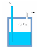
罐2的气压控制模型如图 3所示。
|
图 3 罐2的气压控制模型 Figure 3 Pressure control model for tank 2 |
罐2上连接了一个泄压阀门,阀门外边的压力可视为大气压。由于罐2内的氩气为可压缩流体,将阀门打开后其压力的变化可以用式 (11) 描述[18]:
| $\frac{\text{d}{{P}_{2}}}{\text{d}t}=\frac{\gamma {{P}_{2}}}{{{V}_{\text{a}\text{2}}}}\left( {{Q}_{\operatorname{s}}}-Q \right)$ | (11) |
其中:
| ${{Q}_{\operatorname{s}}}={{v}_{\operatorname{s}}}\frac{\text{ }\!\!\pi\!\!\text{ }{{d}^{2}}}{4}$ | (12) |
| $Q={{\alpha }^{\frac{-1}{\gamma }}}\sqrt{\frac{2}{\gamma -1}\left( {{\alpha }^{\frac{\gamma -1}{\gamma }}}-1 \right)}c{{s}_{\text{e}}}$ | (13) |
式中:Va, 2为罐2内氩气的体积;g为氩气比热容比;Qs为流入熔盐体积流量;Q为阀门流出氩气体积;
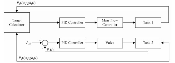
系统控制初步方案如图 4所示。流量标定平台的实验手段是通过气体压力计和储罐液位计按照式 (2) 计算流量计两端的熔盐压差,与式 (5) 决定的目标压差比较后,计算出氩气质量流量控制目标值,调节罐体氩气质量流量实现间接稳定熔盐流量。
|
图 4 系统控制初步方案 Figure 4 Preliminary control system signal diagram |
控制质量流量控制器使用的比例、积分 (Proportion-Integration, PI) 控制器描述如下:
| ${Q_m} = \left\{ {\begin{array}{*{20}{l}} 0&{t < {t_{{\text{start}}}}} \\ \begin{gathered} 2 \times {10^{ - 7}}\left[ {\Delta P\left( t \right) - \Delta {P_0}} \right] + \hfill \\ 5 \times {10^{ - 8}}\int_{{t_{\operatorname{start} }}}^t {\left[ {\Delta P\left( t \right) - \Delta {P_0}} \right]{\text{d}}t} \hfill \\ \end{gathered} &\begin{gathered} \hfill \\ t > {t_{{\text{start}}}} \hfill \\ \end{gathered} \end{array}} \right.$ | (14) |
式中:ΔP0为设定的目标值;ΔP(t) 为t时刻ΔP值;tstart为质量流量控制器开启时间。
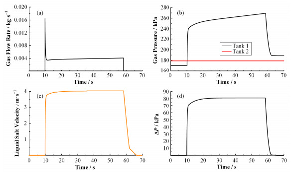
为了获得较大的标定时间,初始状态下罐1装有约120L、罐2装有约0.7L(零液位)温度达650℃的FLiNaK熔盐[19-20]。两个罐都充有一定压力的氩气,由于熔盐在初始时都汇聚在罐1内,罐2内氩气的初始压力略高于罐1内的压力。模拟标定时,使罐2连接的阀门打开,并使用比例、积分和微分 (Proportion-Integration-Differentiation, PID) 算法控制罐2的压力维持不变,10s后通过反馈控制罐1质量流量控制器使系统的目标压差DP不断接近目标值。根据以往实验,在25mm管中流速约为4m·s-1的熔盐,雷诺数达到6000[21],根据式 (2) 计算所需的DP约为80kPa。原始方案的系统参数见表 2。
| 表 2 原始方案的系统参数 Table 2 System parameters of the original scheme |
模拟的结果如图 5所示,为了尽快得到设定的DP,在系统开启时就有巨大的质量流量注入,让熔盐很快加速从管道内流向罐2,其瞬间氩气的质量流量达到了0.015kg·s-1,气体流量控制器在这么大气体质量流量下要保持良好的精度是相当困难的,这对气体质量流量控制器提出了很高的要求[22]。值得注意的是,由于罐2连接的阀门外近似为大气压,且罐2内的气体压力大于大气压,阀门打开后其压力将迅速下降,实际工程中使用PID控制难度较大[23]。为了降低这种要求,本文提出一种新的控制方案,在这种方案中将不再使用PID控制罐2的压力。
|
图 5 原始方案模拟结果 (a) 气体流速,(b) 气体压力,(c) 管道内熔盐流速,(d) 压差 Figure 5 Simulation results of the original proposal. (a) Gas flow rate, (b) Gas pressure, (c) Liquid salt velocity in pipe, (d) Differential pressure |
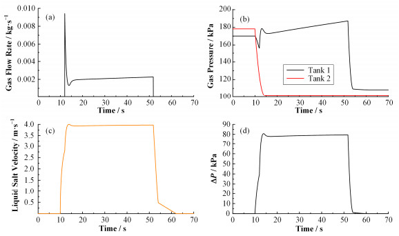
同样,初始状态下将罐2的氩气加压到更高压约180kPa,罐2和大气压的压差保证能为熔盐提供较大的初始流速,这样会降低罐1气体质量流量计试验瞬间的控制难度。实验开始时,直接打开罐2的阀门,让罐2内的压力自然下降,2s后打开PID控制的罐1进气的质量流量控制器,以控制流速稳定到目标值。优化方案的系统参数见表 3。
| 表 3 优化方案的系统参数 Table 3 System parameters of the optimal scheme |
优化方案的模拟结果如图 6所示。在10s时打开罐2阀门,罐2内气体压力快速下降到大气压,熔盐在管道内的流速快速上升,2s后罐1进气质量流量控制器打开,稳定控制。由图 6可以看出,最终可以获得稳定的标定时间达到40s。
|
图 6 优化方案的模拟结果 (a) 气体流速,(b) 气体压力,(c) 管道内熔盐流速,(d) 压差 Figure 6 Simulation results of the optimal proposal. (a) Gas flow rate, (b) Gas pressure, (c) Liquid salt velocity in pipe, (d) Differential pressure |
通过比较表 2、3两个方案的参数,不难看出这种实验方案具有以下优点:1) 稳定时间长;2) 熔盐速度上升快;3) 注气需气量少;4) 注气温度影响降低;5) 系统控制难度降低;6) 用盐量少;7) 质量流量最大不超过0.01kg·s-1,降低了对质量流量控制器的要求。
4 误差分析根据式 (5) 得到管道内流量的相对误差表达式:
| $\frac{{{S}_{{{Q}_{v}}}}}{{{Q}_{v}}}=\sqrt{{{\left( \frac{\partial \ln {{Q}_{v}}}{\partial d}{{S}_{d}} \right)}^{2}}+{{\left( \frac{\partial \ln {{Q}_{v}}}{\partial \Delta P}{{S}_{\Delta P}} \right)}^{2}}+{{\left( \frac{\partial \ln {{Q}_{v}}}{\partial \rho }{{S}_{\rho }} \right)}^{2}}+{{\left( \frac{\partial \ln {{Q}_{v}}}{\partial {{\xi }_{\operatorname{p}}}}{{S}_{{{\xi }_{\operatorname{p}}}}} \right)}^{2}}}$ | (15) |
式中:
| $\frac{{{S}_{{{Q}_{v}}}}}{{{Q}_{v}}}\approx \left( \frac{\partial \ln {{Q}_{v}}}{\partial \Delta P} \right){{S}_{\Delta P}}=\frac{{{S}_{\Delta P}}}{2\Delta P}$ | (16) |
其中:
| ${{S}_{\Delta P}}=\sqrt{\frac{{{\sum{\left( \Delta {{P}_{i}}-\overline{\Delta P} \right)}}^{2}}}{n-1}}$ | (17) |
根据最后的模拟结果,选择30-50s之间流速较为稳定的时间作为流量标定时间。在这个时间段中,模拟得到的数据算出
表 4列出了三种时间分辨率情况下系统误差情况,商用PLC设备的典型时间分辨率为100ms,而基于PXI机箱的数据采集板卡时间分辨率远小于1ms。另外按照硬件规格书上描述的测量精度,在误差分析过程中相继增加了系统仪表误差、气体压力计、液位计、质量流量控制器,见表 5所示。
| 表 4 不同参数的相对误差对比 Table 4 Error analysis for different system parameters (%) |
| 表 5 仪控元件的性能参数 Table 5 Performance parameters of instrument and control instruments |
分析结果表明,在1ms的时间分辨率,考虑气体压力计、液位计、质量流量控制器误差的情况下,系统的标定误差最小可达到1.41%。而使用PLC作控制设备最小误差也达到2%。在不考虑器件非线性和时间响应对结果影响的前提下,我们选用时间分辨率更高的美国国家仪器有限公司 (National Instruments, NI) 面向仪器系统的PCI扩展平台 (PCI extensions for Instrumentation, PXI) 数据采集 (Data Acquisition, DAQ) 板卡实现数据采集和过程控制逻辑实施。
5 结语本文通过理论推导给出了气压稳定熔盐流量的可行性方案,通过闭环控制气体质量流量,实现流量计两端压差稳定并达到4m·s-1目标流量。经过优化方案,设定初始熔盐液位差,达到减少了熔盐(体积 < 0.1m3)、惰性气体用量,降低质量流量计的指标要求(最大质量流量 < 0.01kg·s-1)的目的。经过计算可得到40s的稳定流量标定时间,理论标定误差约为1%。
本文提出的高温熔岩标定方法在理论上适用于大部分液体流量标定。在被标定介质汽化不严重的情况中,其温度、密度等并不影响此标定方法的使用。在已经取得了介质相关雷诺数的情况下,这是一种节省成本熔盐流量标定方法,通过修改标定参数也可应用到其它液体流量计标定。
| [1] | Abram T, Ion S. Generation-Ⅳ nuclear power:a review of the state of the science[J]. Energy Policy, 2008, 36(12): 4323–4330. DOI: 10.1016/j.enpol.2008.09.059 |
| [2] |
江绵恒, 徐洪杰, 戴志敏. 未来先进核裂变能——TMSR核能系统[J].
中国科学院院刊, 2012, 27(3): 366–374.
JIANG Mianheng, XU Hongjie, DAI Zhimin. The future of advanced nuclear fission energy-TMSR China nuclear power system[J]. Bulletin of Chinese Academy of Sciences, 2012, 27(3): 366–374. DOI: 10.3969/j.issn.1000-3045.2012.03.016 |
| [3] |
金愿, 程进辉, 王坤, 等. 几种典型熔盐冷却剂的热物性研究[J].
核技术, 2016, 39(5): 050604.
JIN Yuan, CHENG Jinhui, WANG Kun, et al. Thermal study several typical molten salt coolant[J]. Nuclear Techniques, 2016, 39(5): 050604. DOI: 10.11889/j.0253-3219.2016.hjs.39.050604 |
| [4] | MeinecKe W, Bohn M. Solar energy concentrating systems, applications and technologies[M]. Germany: Heidelberg, 1995. |
| [5] | Ho C, Mehos M, Turchi C, et al. Probabilistic analysis of power tower systems to achieve sunshot goals[J]. Energy Procedia, 2014, 49(1): 1410–1419. DOI: 10.1016/j.egypro.2014.03.150 |
| [6] |
朱建坤.太阳能高温熔盐传热蓄热系统设计及实验研究[D].北京:北京工业大学, 2006.
ZHU Jiankun.Heat transfer heat storage system design and experimental study of solar high-temperature molten salt[D].Beijing:Beijing University of Technology, 2006. |
| [7] | Gill D D, Kolb W J, Briggs R J.An evaluation of pressure and flow measurement in the molten salt test loop (MSTL) system[R].SAND2013-5366, US:Sandia National Laboratories, 2013. |
| [8] | Tallackson J R, Moore R L, Ditto S J.Instrumentation and controls development for molten-salt breeder reactors[R].ORNL-TM-1856, US:Oak Ridge National Laboratory, 1967. |
| [9] | Li J H.Calibration of flow meter by standard meter method and evaluation of uncertainty[C].Proceedings of the 12th International Conference on Flow Measurement, Beijing, 2004:5. |
| [10] | Yermishin S M, Lopatin A V, Dulev V A, et al.Measuring set including a virtual standards technology-based superimposed ultrasonic flow meter[C].Proceedings of the 12th International Conference on Flow Measurement, Beijing, 2004:6. |
| [11] | Liu Q, Wang R D, Zhu Y, et al.An algorithm to eliminate stochastic jump measurements of ultrasonic flow-meter with time difference method[C].Intelligent Information Technology Application Association, Manufacturing Systems and Industry Application, Beijing, 2011:8. |
| [12] |
孙露, 孙立成, 阎昌琪. ORNL 10 MW熔盐实验堆 (MSRE) 排盐罐冷却系统热工水力特性分析[J].
核技术, 2012, 35(10): 790–794.
SUN Lu, SUN Licheng, YAN Changqi. ORNL 10 MW molten salt experimental reactor (MSRE) salt drainage tank cooling system thermal hydraulics analysis[J]. Nuclear Techniques, 2012, 35(10): 790–794. |
| [13] |
卢洋, 贺建, 朱志强, 等. 液态铅铋电磁流量计初步标定实验与分析[J].
核技术, 2014, 37(8): 080603.
LU Yang, HE Jian, ZHU Zhiqiang, et al. Preliminary calibration test and analysis of electromagnetic flow-meter in liquid lead-bismuth[J]. Nuclear Techniques, 2014, 37(8): 080603. DOI: 10.11889/j.0253-3219.2014.hjs.37.080603 |
| [14] |
陈道龙. 永磁式钠流量计的研制[J].
核动力工程, 1991, 12(2): 26–33.
CHEN Daolong. Development of permanent magnet sodium meter[J]. Nuclear Power Engineering, 1991, 12(2): 26–33. |
| [15] |
吴宜灿, 黄群英, 朱志强, 等. 中国系列液态锂铅实验回路设计与研发进展[J].
核科学与工程, 2009, 29(2): 161–169.
WU Yican, HUANG Qunying, ZHU Zhiqiang, et al. Liquid lithium lead test circuit design and development progress in China[J]. Nuclear Science and Engineering, 2009, 29(2): 161–169. |
| [16] |
陈五星, 夏庚磊, 彭敏俊. 中国实验快堆主冷却系统建模与仿真研究[J].
核动力工程, 2014, 35(2): 105–109.
CHEN Wuxing, XIA Genglei, PENG Minjun. Chinese experimental fast modeling and simulation of the primary cooling system[J]. Reactor Nuclear Power Engineering, 2014, 35(2): 105–109. |
| [17] |
王俊涛, 桑培勇. 可变粘度液体流量标准装置的研究[J].
工业计量, 2013, 23(4): 27–29.
WANG Juntao, SANG Peiyong. Variable viscosity liquid flow standard device[J]. Industrial Measurement, 2013, 23(4): 27–29. |
| [18] |
李复. 可压缩流体的伯努利方程[J].
大学物理, 2008, 27(8): 15–18.
LI Fu. Bernoulli's equation for compressible flow[J]. College Physics, 2008, 27(8): 15–18. |
| [19] |
汪全全, 尹聪聪, 孙雪静, 等. TMSR核功率控制系统的PID设计与仿真[J].
核技术, 2015, 38(2): 020601.
WANG Quanquan, YIN Congcong, SUN Xuejing, et al. PID design and simulation of TMSR nuclear power control system[J]. Nuclear Techniques, 2015, 38(2): 020601. DOI: 10.11889/j.0253-3219.2015.hjs.38.020601 |
| [20] |
宗国强, 陈博, 张龙, 等. FLiNaK熔盐的制备[J].
核技术, 2014, 37(5): 050604.
ZONG Guoqiang, CHEN Bo, ZHANG Long, et al. Preparation of FLiNaK molten salt[J]. Nuclear Techniques, 2014, 37(5): 050604. DOI: 10.11889/j.0253-3219.2014.hjs.37.050604 |
| [21] | Ignatiev V V, Feynberg O S, ZagnitKo A V, et al. Molten salt reactors:new possibilities, problems and solutions[J]. Atomic Energy, 2012, 112(3): 157–165. DOI: 10.1007/s10512-012-9537-2 |
| [22] | Zhou J G, Zhang J Z.Monte Carlo simulation on automatic calibration method of horizontal tanks[C].Proceedings of 2014 International Conference on Industrial Engineering and Information Technology, Beijing, 2014:3. |
| [23] | Fan S W, Cao Z, Xu L J, et al. Numerical solution of the weight function for electromagnetic flowmeter[J]. Computer Aided Drafting Design & Manufacturing, 2010, 20(2): 36–41. |


