With the increase of installed capacity of distributed inverters in power system, the proportion of installed capacity of traditional synchronous generators gradually decreases [1, 2]. Due to the lack of inertia and damping of traditional synchronous generators in distributed generation systems with power electronic converters, power systems are more vulnerable to power fluctuations and system faults [3, 4]. Virtual synchronous generator (VSG) enables the distributed generation based on grid-connected inverters to simulate or partially simulate the frequency and voltage control characteristics of synchronous generators from the external characteristics, which can provide certain inertia and damping for the grid, thereby improving the stability of the distributed system [5].
The concept of virtual synchronous generator was first proposed in Ref. [6]. The ontology model of VSG is established, and the design of the parameters for control loop is completed [7, 8]. On this basis, the flexibility of VSG is enhanced by improving the control without frequency difference [9-11]. The influence of inertia on the output characteristics of VSG is analyzed. By introducing frequency variation into inertia control to form adaptive control of inertia [12-15], the advantages of virtual inertia in improving frequency stability of microgrid system are demonstrated. The high-order small signal model of VSG is constructed [16]. The idea of virtual synchronous generator is applied to the field of wind power generation, which reflects its universality [17, 18].
Many literatures have studied the grid-connected control strategy of VSG. The influence of VSG parameter perturbation on grid-connected power tracking is quantitatively analyzed, and the influence of virtual inertia and damping parameters on the system and the tuning method [19]. The small signal stability of VSG under grid-connected and off-grid modes is analyzed. It is pointed out that the variation of inertia time constant, damping coefficient and reactive power sag coefficient has great influence on system stability [20]. Based on the "power-voltage-current" three-loop control strategy with pre-synchronization device, seamless switching between grid-connected and off-grid operation modes of VSG is realized [21].
The above researches on VSG are all based on the condition that the grid voltage does not contain harmonics. However, in actual operation, the grid voltage often contains harmonics, which will introduce the same frequency harmonics to the grid-connected current and directly affect the output current quality of VSG. In order to ensure the quality of grid-connected power, a series of standards and technical specifications have been formulated by relevant departments at home and abroad [22-26]. For the control of conventional inverters under grid voltage distortion, a double closed-loop control strategy based on inductance voltage differential and grid-connected current feedback is proposed [27]. A direct power control strategy based on resonant sliding mode is proposed [28]. The stability and convergence of the proposed control strategy are analyzed in depth. In order to improve the instantaneous current overshoot during the fault ride through of inverters, the phase advance compensation link of the feed-forward component of the grid voltage is introduced into the current loop [29]. A flexible harmonic control method for three-phase grid-connected inverters without harmonic detection is proposed [30]. For the control of VSG under grid voltage distortion, a method combining virtual impedance with phasor current limiting is proposed for direct voltage system, which effectively limits the transient and steady components of fault current [31]. By controlling the reference values of positive and negative sequence currents separately, the output balanced current of VSG under unbalanced grid voltage is achieved [32-34]. A novel voltage feed-forward compensation strategy based on notch filter is proposed, which can suppress the harmonic with particular order of grid-connected current [35]. An improved algorithm of inductance current reference value based on double second-order generalized integral is proposed [36]. The influence of harmonics caused by grid voltage is eliminated by feedforward method, which improves the quality of output current in the whole frequency domain. However, the full feedforward control process of grid voltage needs differential operation, and it is easy to introduce additional harmonic components and slow the response time.
On the basis of the existing research, an improved VSG control strategy is proposed to deal with the harmonics of power grid. Firstly, an improved algorithm of inductance current reference value based on double second-order generalized integral is added. Secondly, the differential operation needed in the full feed-forward control process of grid voltage is replaced by inertial integral. Finally, the corresponding current regulator is selected to realize current tracking, so as to achieve the purpose of harmonic suppression. The simulation and experimental results prove the correctness and effectiveness of the proposed control strategy.
2 Basic Principles of VSGVSG simulates the rotor equation of synchronous generator. In active-frequency control, virtual inertia and damping are introduced. In reactive-voltage control, excitation regulation of synchronous generator is simulated. The governing equation is:
| $\frac{{{P}_{\text{ref}}}-{{P}_{\text{e}}}}{\omega }=J\frac{d\omega }{dt}+D\Delta \omega $ | (1) |
| $\Delta \omega =\omega -{{\omega }_{0}} $ | (2) |
| $ V={{V}_{0}}+{{D}_{\text{q}}}\left( {{Q}_{\text{ref}}}-Q \right) $ | (3) |
where Pref and Pe are the given active power and electromagnetic power of VSG; ω and ω0 are the angular frequency of VSG and the angular frequency of power grid; J and D are the inertia and damping coefficient of VSG; Qref and Q are the given and actual value of reactive power; V0 and V are the rated and measured voltage values; Dq is the reactive power-voltage sag coefficient.
The control block diagram of VSG is shown in Fig. 1. The amplitude and phase angle of reference voltage are obtained through VSG control algorithm by Pref and Qref, and the voltage reference instruction is output.

|
Fig.1 Control block diagram of VSG |
3 Improved VSG Control Strategy for Harmonics in Power Grid 3.1 Equivalent Model Analysis of VSG
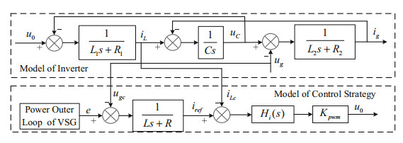
The control block diagram is shown in Fig. 2 when the feedback control scheme of grid voltage and inverter side current is adopted.
|
Fig.2 Equivalent model of grid voltage and inverter side current feedback control scheme |
In Fig. 2, ugc and iLc are respectively measured values of grid voltage and inverter side current. According to the control block diagram shown in Fig. 2, the closed-loop transfer function of the system is obtained:
| $ {{i}_{g}}={{G}_{i}}\left( s \right){{i}_{ref}}+{{G}_{g}}\left( s \right){{u}_{g}} $ | (4) |
Where
| $ \left\{ \begin{array}{l} {i_{ref}} = \frac{1}{{Ls + R}}\left( {e- {u_{gc}}} \right)\\ {G_i}\left( s \right) = \frac{{{H_i}\left( s \right){K_{pwm}}}}{{D\left( s \right)}}\\ {G_g}\left( s \right) = \frac{{{H_i}\left( s \right){K_{pwm}}Cs + {L_1}C{s^2} + {R_1}Cs + 1}}{{D\left( s \right)}}\\ D\left( s \right) = \left( {{L_2}C{s^2} + {R_2}Cs + 1} \right){H_i}\left( s \right){K_{pwm}} + {L_1}{L_2}C{s^3}\\ + \left( {{R_1}{L_2} + {R_2}{L_1}} \right)C{s^2} + \left( {{R_1}{R_2}C + {L_2} + {L_1}} \right)s + {R_1} + {R_2} \end{array} \right. $ |
It can be seen that the grid-connected current of LCL grid-connected inverters with current feedback on the inverter side is affected by the reference value of inductance current on the one hand, and the grid voltage on the other. In actual operation, when the grid voltage contains certain harmonics, the grid voltage can be decomposed into fundamental component and harmonic component. Correspondingly, the reference value of inductance current is affected by grid voltage, which contains fundamental component and harmonic component. At the same time, the disturbance component of grid voltage to grid current also contains harmonic component, which directly makes grid-connected point current contain a large number of harmonics. If the control parameters or filter parameters are not properly designed, the quality of grid current may be lower than some standard provisions, which is disadvantageous in the stable operation of the system.
Therefore, it is necessary to improve the control strategy from two aspects: improving the reference value of inductance current and eliminating the influence of grid voltage. Because of the low bandwidth of power loop, the reference value of output voltage generated by VSG power outer loop contains only the positive sequence component of fundamental wave. From the expression of iref, it can be seen that the reference value of inductance current is directly related to the measured value of grid voltage. Therefore, for the improvement of the reference value of inductance current, it is necessary to extract the fundamental component of the measured value with grid voltage to calculate the reference value of inductance current without harmonic effect. For the improvement of grid voltage, it is necessary to add a specific feedback link in the control loop to eliminate the influence of ug on the output current.
3.2 Extraction of Inductance Current Reference Value Based on Improved Double Second-Order Generalized IntegralThe equivalent model of VSG shows that the grid voltage with harmonics can be decomposed into fundamental component and harmonic component. If a suitable method is used to extract the fundamental positive sequence component of the grid voltage measurement for calculating the reference value of inductance current, the reference value will only contains the fundamental component, and the harmonic component of the grid current will be greatly suppressed.
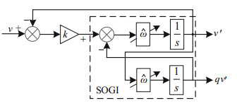
Among the commonly used methods for extracting positive sequence components of fundamental wave, the method based on double second-order generalized integral (DSOGI) has small delay and good dynamic performance. Adding this module will not bring obvious influence to the whole control link. Therefore, the improved DSOGI will be selected to extract the positive sequence component of fundamental voltage and calculate the reference value of inductance current. Figure 3 is the principle block diagram of quadrature signal generator based on second-order generalized integrator (SOGI-QSG), where v is the input, and v′ and qv′ are the two outputs of signal generator. The fundamental positive sequence components of v′ and v are equal in amplitude and phase, and the amplitudes of qv′ and v are equal, but their phase lag is 90°.
|
Fig.3 An adaptive filter based on SOGI-QSG |
Judgment of the value of k in quadrature signal generator: From Fig. 3, it can be seen that the transfer function of SOGI-QSG system is as follows:
| $ D\left( s \right) = \frac{{v'\left( s \right)}}{{v\left( s \right)}} = \frac{{k\omega s}}{{{s^2} + k\omega s + {\omega ^2}}} $ | (5) |
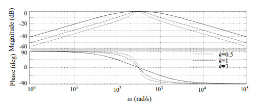
From the bode diagram of Fig. 4, it can be seen that the smaller the value of k, the better the filtering effect, but the slower the response speed. Therefore, according to the actual compromise, considering the filtering effect and response time,
|
Fig.4 Bode diagram of the relationship between D(s) and k |
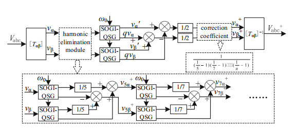
The principle block diagram of fundamental positive sequence component extraction is shown in Fig. 5. Where vα and vβ are the components of α and β axes of grid voltage in two-phase stationary coordinates, and vα+ and vβ+ are the positive sequence components of fundamental wave of extracted grid voltage in α and β axes, respectively. ω0 is the fundamental wave angle frequency. The improved principle block diagram of fundamental positive sequence component extraction is shown in Fig. 6. Because the positive sequence separation method based on DSOGI-QSG will be affected by harmonics when the grid voltage contains multiple harmonics, a harmonic elimination module is added in Fig. 6 to eliminate the influence of each harmonic on the extraction of fundamental components. Where, the value of n is the highest number of harmonics.

|
Fig.5 Fundamental positive sequence component separation based on DSOGI-QSG |
|
Fig.6 An improved block diagram for extracting positive sequence components of fundamental wave based on DSOGI-QSG |
Formula (6) is obtained from the harmonic elimination module in Fig. 6.
| $ \left\{ {\begin{array}{*{20}{r}} {v_{5\alpha \beta }^ + = \left( {\frac{1}{5}- 1} \right){v_{\alpha \beta }}}\\ {v_{7\alpha \beta }^ + = \left( {\frac{1}{7}- 1} \right)v_{5\alpha \beta }^ + }\\ \vdots \\ {v_{n\alpha \beta }^ + = \left( {\frac{1}{n}- 1} \right)v_{(\mathit{n} -1)\alpha \beta }^ + } \end{array}} \right. $ | (6) |
Therefore, vnαβ+ = (1/5-1)(1/7-1)…(1/n-1)vαβ, The correction coefficient in Fig. 6 can be obtained as follows:
| $ \frac{1}{{\left( {1/5 -1} \right)\left( {1/7- 1} \right) \cdots \left( {1/n -1} \right)}} $ |
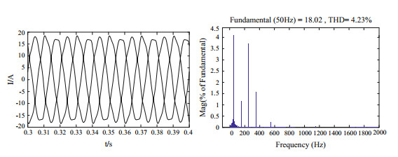
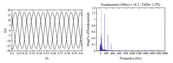
Comparison for simulation results of voltage fundamental wave positive sequence component extraction before and after improvement. The simulation conditions are as follows: the grid voltage contains 5% 5th and 7th harmonics, 2% 11th and 23rd harmonics. Figures 7 and 8 are the simulation results of iref before and after improvement.
|
Fig.7 Simulation results of iref before improvement |
|
Fig.8 Simulation results of iref after improvement |
By comparing the simulation results of Figs. 7 and 8, it can be seen that by extracting the fundamental positive sequence component of the grid voltage measurement, the inductance current reference value is greatly improved, and the harmonic distortion rate of inductance current reference is lower.
From the above analysis, it can be known that the harmonic content of the reference value of inductance current which needs to be tracked decreases after adding the improved double second-order generalized integral algorithm, so that the harmonic component of grid-connected current can be better suppressed.
3.3 Full Feed-Forward Control of Grid Voltage Based on Inertial Integral LinkIt can be known from Eq. (1) that the LCL grid-connected inverter adopts the improved inductor current reference value strategy, which can only partially eliminate the influence of the grid voltage on the grid-connected point current. Therefore, it is necessary to find out the grid voltage feed-forward strategy suitable of the current on the inverter side feedback for LCL grid-connected inverter, so as to eliminate the influences of grid voltage on the grid-connected point current. It can be seen from Fig. 2 that the position suitable for feeding the grid voltage signal into the actual control system can only be before and after the current regulator, as shown in Fig. 9, where A and B are the transfer functions to be determined.

|
Fig.9 Feedforward control of grid voltage |
Figure 9 shows that:
| $ {i_g} = {G_i}\left( s \right){i_{ref}} + {G_{gf}}\left( s \right){u_g} $ | (7) |
where
| $ {G_{gf}}\left( s \right) = \frac{{\left( {A- Cs} \right){H_i}\left( s \right){K_{pwm}} + B{K_{pwm}} - \left( {{L_1}C{s^2} + {R_1}Cs + 1} \right)}}{{D\left( s \right)}} $ |
To completely eliminate the impact of grid voltage on grid current, it must meet:
| $ \left\{ \begin{array}{l} A = Cs\\ B = \frac{{{L_1}C{s^2} + {R_1}Cs + 1}}{{{K_{pwm}}}} \end{array} \right. $ | (8) |
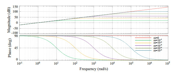
As can be seen from Eq. (8), the transfer functions A and B contain differential operations, which is easy to introduce additional harmonic components. Therefore, this paper considers the differential link to be replaced by the inertial integral link to make the same effect. The inertia integral link transfer function is expressed by Eq. (9), where m is an approximation coefficient.
| $ F\left( s \right) = \frac{s}{{ms + 1}} $ | (9) |
Figure 10 shows the bode diagram of F(s) when m takes different values. As the coefficient decreases, the frequency domain characteristics of F(s) coincide with the differential link more and more. Considering the harmonic number and the harmonic content in the actual system, the better effect can be achieved when m = 10-4, which reduces the additional harmonic components brought by differential operation to the system.
|
Fig.10 Bode diagram of F(s) with different values of m |
After adding the feed-forward term of the grid voltage, the transfer function of the grid current is as follows:
| $ {i_g} = {G_i}\left( s \right){i_{ref}} $ | (10) |
Although the feedback control of the current on the inverter side is adopted, the grid current is closely tracked by the grid voltage feed-forward control strategy, and is not disturbed by the grid voltage. Formula (10) also shows that the characteristic equation of the system remains unchanged after adding the feedforward strategy of grid voltage, so its stability is consistent with that without feedforward strategy of grid voltage. The overall improved control strategy of the system is shown in Fig. 11, where A1 and B1 are the transfer functions A and B which replace the differential terms.

|
Fig.11 Overall improved control strategy |
After improving the reference value of inductance current for harmonic suppression, it is necessary to further suppress the harmonic through the feed-forward control of grid voltage. In the further control, the additional harmonic components caused by differential operation and response time are reduced by adding a specific transfer function after substitution, and the influence of grid voltage on the harmonic content of grid-connected current is eliminated.
Current regulator plays an important role in tracking current reference value and voltage feedback value. It has a certain influence on response time and complexity of control system. Therefore, current regulator is analyzed and selected in the next section.
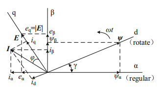
3.4 Analysis and Selection of Current RegulatorFor the vector control method based on grid voltage orientation, when the grid voltage contains harmonics and other disturbances, it will directly affect the detection of fundamental voltage vector phase angle, thus affecting the accuracy and control performance of the vector orientation method. In order to restrain the influence of grid voltage on vector orientation and control performance, the traditional improved method can adopt vector control based on virtual flux orientation.
The structure of vector control based on virtual flux orientation is shown in Fig. 12. Because of the flux vector orientation, the formula for calculating the position angle of the flux vector is as follows:
| $ \left\{ \begin{array}{l} \sin \gamma = \frac{{{\psi _\beta }}}{{\sqrt {\psi _{\rm{ \mathsf{ α} }}^2 + \psi _\beta ^2} }}\\ \cos \gamma = \frac{{{\psi _\alpha }}}{{\sqrt {\psi _{\rm{ \mathsf{ α} }}^2 + \psi _\beta ^2} }} \end{array} \right. $ | (11) |
| $ \left\{ \begin{array}{l} \sin \gamma = \frac{{{\psi _\beta }}}{{\sqrt {\psi _{\rm{ \mathsf{ α} }}^2 + \psi _\beta ^2} }}\\ \cos \gamma = \frac{{{\psi _\alpha }}}{{\sqrt {\psi _{\rm{ \mathsf{ α} }}^2 + \psi _\beta ^2} }} \end{array} \right. $ |
|
Fig.12 Vector diagram of vector control based on virtual flux orientation |
The algorithm block diagram of virtual flux is shown in Fig. 13. In Fig. 13, ωe is the fundamental frequency of the power grid. Generally, according to the optimal range of cut-off frequency, k1 can be set to 0.2-0.3, while k2 is usually set to k1/2, where k1 = 0.2 and k2 = 0.1.

|
Fig.13 Block diagram of the algorithm for virtual flux |
As the VSG control strategy has the following characteristics, in the active-frequency link, the rotor motion characteristics and primary frequency modulation characteristics of synchronous generator are simulated. The reference phase is generated by the active-frequency equation and virtual inertia using the mechanical and electromagnetic power of VSG. Therefore, the reference phase generated here is considered to replace the phase obtained by vector control with virtual flux orientation. Under the same simulation conditions as Sect. 3.2, the comparison results of vector control based on virtual flux orientation and reference phase generated by VSG are shown in Fig. 14.

|
Fig.14 Generates a reference phase contrast based on virtual flux orientation and VSG |
As can be seen from Fig. 14, the reference phase generated by VSG basically coincides with the phase obtained by vector control based on virtual flux orientation. However, the reference phase generated by VSG is a necessary link in the simulation of synchronous generators. This reference phase can be used not only to generate reference voltage, but also in coordinate transformation. As a result, the above-mentioned vector control based on virtual flux orientation is omitted, which makes the control system simpler. Therefore, in this paper, a typical PI regulator combined with the reference phase generated by VSG is used to realize the zero steady-state error control of AC signal.
4 Simulation and Experimental Results 4.1 Simulation ResultsThe improved control strategy proposed in this paper is simulated and tested under the environment of Matlab/Simulink software. Its main parameters are shown in Table 1.
| Table 1 System simulation parameters |
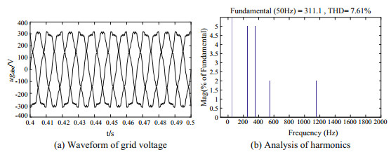
Simulation condition 1: The grid voltage contains 5% of the 5th and 7th harmonics, 2% of the 11th harmonic and 23th harmonic. It is consistent with the voltage harmonic content of the grid in literature [36]. At this time, The waveform of the grid voltage is shown in Fig. 15a, and the harmonic analysis is shown in Fig. 15b. The total harmonic distortion of the grid voltage is 7.61%.
|
Fig.15 Simulation 1: Voltage waveform and harmonic analysis of grid |
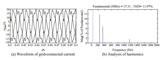
Under the condition of simulation 1, when the improved control strategy is not adopted, the grid-connected current waveform and the A-phase current harmonic analysis are shown in Fig. 16. The grid-connected current THD is as high as 11.97%, which is greater than the national grid-connected standard.
|
Fig.16 Simulation 1: Simulation results without improved control strategy |
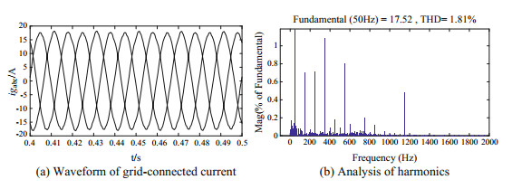
Under the condition of simulation 1, after using the improved strategy proposed in this paper, the grid-connected current waveform and phase-A current harmonic analysis are shown in Fig. 17. The total THD of the grid-connected current dropped to 1.81%, which is in line with the grid-connected standard, and at the same time, the harmonic content was lower than the harmonic content of the simulation results in literature [36].
|
Fig.17 Simulation 1: Simulation results with improved control strategy |
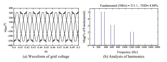
In order to verify that the improved control strategy proposed in this paper is not only effective for specific order harmonics [35], but has the suppression effect on all harmonics in the full frequency domain, setting up simulation condition 2: the grid voltage contains 5% of the 5th harmonic and 7th harmonic, 3% of the 11th harmonic and 13th harmonic, 2% of the 23th harmonic and 25th harmonic. At this time, the waveform of the grid voltage is shown in Fig. 18a, and the harmonic analysis is shown in Fig. 18b. The total harmonic distortion rate of the grid voltage is 8.80%.
|
Fig.18 Simulation 2: Voltage waveform and harmonic analysis of grid |
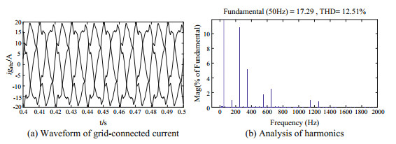
Under the condition of simulation 2, when the improved control strategy is not adopted, the grid-connected current waveform and the A-phase current harmonic analysis are shown in Fig. 19. The grid-connected current THD is as high as 12.51%, which is much larger than the national grid-connected standard.
|
Fig.19 Simulation 2: Simulation results without improved control strategy |
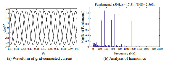
Under the condition of simulation 2, after the improved strategy proposed in this paper, the grid-connected current waveform and phase-A current harmonic analysis are shown in Fig. 20. The total THD of the grid-connected current dropped to 2.56%, which is in line with the grid-connected standard.
|
Fig.20 Simulation 2: Simulation results with improved control strategy |
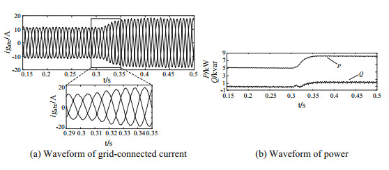
In order to verify the dynamic response performance of the improved control strategy, the active power command value is abruptly changed from 5 to 8 kW at 1.3 s, and the reactive power command value is abrupt from 0 to 1 kvar. At this time, the power simulation result and the grid-connected current waveform are shown in Fig. 21.
|
Fig.21 Simulation results of improved control strategy under power variation |
It can be seen from Fig. 21a, b that when the active power and the reactive power are abrupt, the grid-connected current has a faster response speed, and the harmonics of the grid-connected current can still be well suppressed in the dynamic change process of the power mutation.
Combined with the above simulation results, it can be seen that under the condition that the grid voltage contains harmonics and the power variation, the improved method in the VSG control strategy can suppress the grid-connected current harmonics to a large extent, which proves the correctness and effectiveness of the work done in this paper from the perspective of simulation.
4.2 Experimental ResultsIn order to further verify the correctness and effectiveness of the proposed control method, an experimental platform based on DSP control board is built. The core controller adopts TMS320F28335 of TI company, and the IGBT adopts BSM50GB120DLC of infineon. The condition of experimental 1 is the same as the simulation 1, and the condition of experimental 2 is the same as the simulation two. Under the condition of experiment 2.
Figures 22 and 23 respectively show the experimental results obtained before and after the improvement under the grid voltage of the condition of experimental one. Comparing Figs. 22a and 23a, it can be seen that under the condition of harmonic distortion of the power grid, the grid current waveform distortion is very serious if the improved control method is not adopted, while the grid-connected current waveform is obviously improved when the improved control method is adopted. It can be seen from Figs. 22b and 23b that the grid-connected current harmonic distortion rate is reduced from 12.233 to 2.229% with the improved control strategy.

|
Fig.22 Experiments 1: Experimental results without the improved control strategy |

|
Fig.23 Experiments 1: Experimental results with the improved control strategy |
Figures 24 and 25 respectively show the experimental results obtained before and after the improvement under the grid voltage of the condition of experimental 2. Comparing Figs. 24a and 25a, it can be seen that under the condition of harmonic distortion of the power grid, the grid current waveform distortion is very serious if the improved control method is not adopted, while the grid-connected current waveform is obviously improved when the improved control method is adopted. It can be seen from Figs. 24b and 25b that the grid-connected current harmonic distortion rate is reduced from 13.369 to 3.189% with the improved control strategy.

|
Fig.24 Experiments 2: Experimental results without the improved control strategy |

|
Fig.25 Experiments 2: Experimental results with the improved control strategy |
When the active power and reactive power are abrupt, the experimental results of the output power and the three-phase grid-connected current are shown in Fig. 26.

|
Fig.26 Experimental results of improved control strategy under power variation |
As can be seen from Fig. 26, during the dynamic power change process, the grid-connected current tends to be stable in one cycle, and the current harmonics can be well suppressed. The experimental results show that the improved VSG control strategy for grid harmonics can effectively suppress the harmonic components of grid-connected current and improve the grid-connected power quality.
5 ConclusionIn order to deal with the working conditions of harmonics in the power grid, the VSG control strategy is improved in this paper. The improved method based on double second-order generalized integral is used to extract the fundamental positive sequence component of the grid voltage measurement value, which is used to improve the inductance current reference value. On this basis, replaces the differential operation required for the full feed-forward control process of the grid voltage with the inertial integral link and selects the corresponding current regulator to achieve current tracking, thus eliminating the influence of grid voltage harmonics on the grid-connected current. The feasibility of the proposed control strategy is verified by simulation and experimental results, and the following conclusions are obtained.
(1) The improved method based on double second-order generalized integral is used to extract the fundamental positive sequence component of the grid voltage measurement value, which greatly reduces the harmonic component of the inductance current reference value.
(2) The differential operation needed in the full feedforward control process of grid voltage is replaced by the inertial integral link, which eliminates the additional harmonic components that may be introduced in the differential link and does not affect the response time of the system.
| 1. |
Azmy AM, Erlich I (2005) Impact of distributed generation on the stability of electrical power systems. In: IEEE Power Engineering Society General Meeting, vol 2, 16 June, pp 1056-1063 https://ieeexplore.ieee.org/document/1489354
(  0) 0) |
| 2. |
Tan WS, Hassan MY, Majid MS, et al (2013) Optimal distributed renewable generation planning: a review of different approaches. Renew Sustain Energy Rev
18: 626-645. DOI:10.1016/j.rser.2012.10.039 (  0) 0) |
| 3. |
Zhong Q (2017) Virtual synchronous machines and autonomous power systems. Proc CSEE
37(2): 336-348. (  0) 0) |
| 4. |
van Wesenbeeck MPN, de Haan SWH, Varela P et al (2009) Grid tied converter with virtual kinetic storage. In: 2009 IEEE PowerTech. Bucharest, pp 1-7 https://ieeexplore.ieee.org/document/5282048
(  0) 0) |
| 5. |
Zheng T, Chen L, Chen T, et al (2015) Review and prospect of virtual synchronous generator technologies. Autom Electr Power Syst
39(21): 165-175. (  0) 0) |
| 6. |
Beck HP, Hesse R (2007) Virtual synchronous machine. In: 2007 9th international conference on Electrical Power Quality and Utilisation, Barcelona, Spain, pp 1-6 Improved Control Strategy of Virtual Synchronous … 133 https://ieeexplore.ieee.org/document/4424220
(  0) 0) |
| 7. |
Wu H, Ruan X, Yang D, et al (2015) Modeling of the power loop and parameter design of virtual synchronous generators. Proc CSEE
35(24): 6508-6518. (  0) 0) |
| 8. |
Ding M, Yang X, Su J (2009) Control strategies of inverters based on virtual synchronous generator in a microgrid. Autom Electr Power Syst
33(8): 89-93. (  0) 0) |
| 9. |
Zhao Y, Chai J, Sun X (2016) Flexible virtual governor model based on virtual synchronous generator. Autom Electr Power Syst
40(10): 8-15. (  0) 0) |
| 10. |
Yang J, Liu Y, Pan H, et al (2016) Method of frequent deviation-free control of microgrid inverter based on virtual synchronous generator control. Power Syst Technol
40(7): 2001-2008. (  0) 0) |
| 11. |
Lv Z, Sheng W, Liu H, et al (2017) Application and challenge of virtual synchronous machine technology in power system. Proc CSEE
37(2): 349-359. (  0) 0) |
| 12. |
Song Q, Zhang H, Sun K, et al (2017) Improved adaptive control of inertia for virtual synchronous generators in islanding micro-grid with multiple distributed generation units. Proc CSEE
37(2): 412-423. (  0) 0) |
| 13. |
Miguel A, Torres L, Luiz A, et al (2014) Self-tuning virtual synchronous machines: a control strategy for energy storage systems to support dynamic frequency control. IEEE Trans Energy Convers
29(4): 833-840. (  0) 0) |
| 14. |
Alipoor J, Miura Y, Ise T (2014) Power system stabilization using virtual synchronous generator with adoptive moment of inertia. IEEE J Emerg Sel Top Power Electron
3(2): 451-458. (  0) 0) |
| 15. |
Cheng C, Yang H, Zen Z, et al (2015) Rotor inertia adaptive control method of VSG. Autom Electr Power Syst
39(19): 82-89. (  0) 0) |
| 16. |
D'Arco S, Suul JA, Fosso OB (2015) A virtual synchronous machine implementation for distributed control of power converters in smartgrids. Electr Power Syst Res
122(6): 180-197. (  0) 0) |
| 17. |
Wang S, Hu J, Yuan X (2015) Virtual synchronous control for grid-connected DFIG-based wind turbines. IEEE J Emerg Sel Top Power Electron
3(4): 932-944. DOI:10.1109/JESTPE.2015.2418200 (  0) 0) |
| 18. |
Zhao Y, Chai J, Sun X (2015) Virtual synchronous control of grid-connected DFIG-based wind turbines. In: 2015 IEEE Applied Power Electronics Conference and Exposition (APEC), Charlotte, NC, USA, pp 2980-2983 https://ieeexplore.ieee.org/document/7104775
(  0) 0) |
| 19. |
Lü Z, Sheng W, Zhong Q (2014) Virtual synchronous generator and its applications in micro-grid. Proc CSEE
34(16): 2591-2603. (  0) 0) |
| 20. |
Meng J, Wang Y, Shi X, et al (2014) Control strategy and parameter analysis of distributed inverters based on VSG. Trans China Electrotechnical Soc
29(22): 1-10. (  0) 0) |
| 21. |
Shi R, Zhang X, Xu H, et al (2017) The active and reactive power control of virtual synchronous generator based on adaptive mode switching. Trans China Electrotechnical Soc
32(12): 127-137. (  0) 0) |
| 22. |
IEEE Recommended Practice for Utility Interface of Photovoltaic (PV) Systems. IEEE Standard 929, 2000
(  0) 0) |
| 23. |
IEEE Standard for Interconnecting Distributed Resources with Electric Power Systems. IEEE Standard 1547, 2003 https://ieeexplore.ieee.org/document/1225051
(  0) 0) |
| 24. |
Generating Plants Connected the Medium-Voltage Network. BDEW technical guideline, 2008
(  0) 0) |
| 25. |
Technical rule for distributed resources connected to power grid. State Grid Corporation Enterprise Standard Q/GDW480 2010
(  0) 0) |
| 26. |
Technical rule for connecting photovoltaic power station to power grid. State Grid Corporation Enterprise Standard Q/GDW617 2011
(  0) 0) |
| 27. |
Wang X, Ruan X, Liu S (2011) Control strategy for grid-connected inverter to suppress current distortion effected by background harmonics in grid voltage. Proc CSEE
31(6): 7-14. (  0) 0) |
| 28. |
Quan Y, Nian H (2014) Resonance-based sliding mode control of grid connected inverters under unbalanced and harmonic grid voltages. Proc CSEE
34(9): 1345-1352. (  0) 0) |
| 29. |
Wei Z, Wang J, Ru X, et al (2016) Zero voltage ride-through control strategy of photovoltaic grid-connected inverter based on compensation for phase of feed-forward grid voltage. Autom Electr Power Syst
40(4): 78-84. (  0) 0) |
| 30. |
Huang Y, Luo A, Wang Y (2016) A flexible harmonic control method for three-phase grid-connected inverter without harmonic detection. Trans China Electrotechnical Soc
31(24): 213-222. (  0) 0) |
| 31. |
Shang L, Hu J, Yuan X, et al (2017) Modeling and improved control of virtual synchronous generators under symmetrical faults of grid. Proc CSEE
37(2): 403-411. (  0) 0) |
| 32. |
Chen T, Chen L, Wang Y, et al (2016) Balanced current control of virtual synchronous generator considering unbalanced grid voltage. Power Syst Technol
40(3): 904-909. (  0) 0) |
| 33. |
Wan X, Hu H, Nie X, et al (2017) An improved control strategy for virtual synchronous generator under unbalanced grid voltage. Power Syst Technol
41(11): 3573-3581. (  0) 0) |
| 34. |
Tianwen Z, Laijun C, Yan G, et al (2017) Comprehensive control strategy of virtual synchronous generator under unbalanced voltage conditions. IET Gener Transm Distrib
, 1621-1629. (  0) 0) |
| 35. |
Geng Y, Tian F, Sun S, et al (2018) A method of current harmonics suppression based on VSG. Trans China Electrotechnical Soc
33(5): 1040-1050. (  0) 0) |
| 36. |
Chen J, Shen P, Wei T, et al (2018) Control scheme for synchronverters under non-ideal grid condition. Autom Electr Power Syst
9(42): 127-133. (  0) 0) |
 2020 : 115-135 DOI: 10.1007/978-981-13-9783-7_10


