
Quantum Spin Transport in Rashba Spin-Orbit-Coupled Graphene Nanoflakes
Cite this Article
Nikoofard H., Laghaei M., Heidari Semiromi E.. Quantum Spin Transport in Rashba Spin-Orbit-Coupled Graphene Nanoflakes
. Communications in Theoretical Physics, 2017, 67(3): 341 
Permissions
Quantum Spin Transport in Rashba Spin-Orbit-Coupled Graphene Nanoflakes
† Corresponding author. E-mail:
The authors are grateful to University of Kashan for supporting this work by Grant No. 463821/03
Abstract
Abstract
We study the spin-resolved transport in a two-terminal graphene nanoflake device with a Rashba spin-orbit coupling region in the center of the device. The Green’s function method is applied to the system and the spin transmission probability and the spin polarization in x, y, and z directions are calculated. It is found that the components of the spin polarization are antisymmetric functions of Fermi energy, which oscillate and decay to the zero with increasing the energy for all values of the Rashba strength. It is shown that by tuning the Rashba strength via a gate voltage and/or changing the size of the system, it is possible to control the sign and magnitude of the spin polarization. The system represented here is a typical candidate for full electrical spintronic devices based on the carbon materials that are used for spin filtration.
1 Introduction
Study and manufacturing of electronic nanodevices are the main interests of engineers and researchers in fundamental sciences. This is because these systems are fast and have low power dissipation for storage and transport of information. The appearance of the spintronics as a new branch of electronics has opened a wide horizon in this technology, which is the development of spin-based nanodevices to enhance storage capacity and enable encoding and fast processing of the information.[1] Quantum transport, which is the investigation of polarization of the spin of the electrons, has a substantial role in the spintronics and has been studied widely in mesoscopic systems. As an example, the quantum transport has effects in significant phenomena such as quantum Hall effect and it would allow for spin currents to be generated without dissipation.[2]
The spin polarization in a mesoscopic system is generally achieved by an external magnetic field or by connecting the system to a ferromagnetic material. However, in recent years, the generation and manipulation of the spin currents by full electrical means such as spin-orbit coupling (SOC) have become subjects of interest. If the mirror symmetry is broken, either by a perpendicular electric field via a gate voltage or by interaction with a substrate, a Rashba SOC (RSOC) is revealed.[3] The RSOC as an external electric field causes switching and control on the orientation of the spin of electron. When the electric current flows in a sheet, the spin of the electrons become polarized as a result of the cooperation of the current and the Rashba field that is assured with the presence of the substrate.[4] The tuning of the RSOC strength via the external gates[3,5] is simpler than with a magnetic field, so the two-dimensional electron systems with RSOC have become the most promising devices for spintronic applications.
Many studies have been performed on the SOC in nanostructures as a possible electrical way, which allow generation and manipulation of the spin current. For example, it is observed experimentally that a spin-polarized current is generated in a semiconductor wire due to a lateral SOC induced by an in-plane electric field.[6] Moreover, the SOC applied on a segment of the quantum wire in the presence of a constriction[7] generates a spin polarization and enhances the spin-filtering up to %95. Other studies show that the SOC can lead to the spin Hall effect in semiconductor systems.[8–11]
Understanding of the novel features of the graphene such as weak intrinsic SOC and hyperfine couplings[12] has been of interest in recent years. In particular, graphene-based transistors[13] and field-effect transistors (FET)[14] can cause an evolution in the nanoelectronics. The carbon-based devices have a controllable band structure, so it is important to investigate the quantum transport properties of these systems.[15] For example, the spin transport has been measured in suspended high-mobility graphene devices that are connected to ferromagnetic leads.[16]
Several experimental reports have shown that RSOC in graphene can be larger than 200 meV[17] and the quantum spin Hall effect can occur in graphene.[18] Such observations have motivated the scientists to study the effect of the SOC in the graphene-based systems. The effect of SOC on the electronic structure of the graphene opens a small gap in the band energy. This allows the graphene to convert from a two-dimensional semiconductor to an insulator with a quantized spin Hall conductance.[18–19]
The spin conductivity as a striking feature of the graphene can be analyzed based on the Kubo and Landauer formulas.[5] The spin-dependent transport of the graphene nanoribbons have been studied in the presence of an electric-field-induced Rashba coupling in the finite region of the system by consideration of some symmetries.[20] Also, the effect of symmetry and defect on transport properties in zigzag graphene nanoribbons are investigated.[21] A perfect spin-filtering effect and a rectifying behavior are observed for edge hydrogenated graphene nanoribbon heterojunctions.[22] The spin polarization and conductance have been calculated in a Y-shape graphene nanoribbon with three terminals in the presence of the RSOC.[23] In the case of a T-shaped conductor, the effects of the RSOC on the spin-dependent transmission probabilities and the spin filtration have been obtained.[24–26] A large spin-filtering is observed in graphene nanoribbons with zigzag edges in the presence of RSOC.[26] A similar work has performed very recently that the spin polarization has been studied using a gate voltage through a Rashba barrier in the graphene. It found that the sign of the spin polarization can switch from positive to negative by adjusting the electric potential at any RSOC.[27] There also exist technological applications of the grephene in spintronic devices. The graphene nanostrips can be used as digital memory devices in which the spin-polarized states can be treated as switchable quantum bits through the applied voltage.[28]
In this paper, we consider graphene nanodisks with various sizes as channels deposited on a substrate for inducing the RSOC. The channel is connected to semi-infinite nanoribbons with armchair edges as the leads. The RSOC is provided by an underneath gate voltage applied to the central region of the device. In our approach, we start with a single-particle Green’s function in the tight-binding model to calculate the transmission probability and the spin polarization of the electrons. Moreover, the spin polarization of the device in three directions is obtained by tuning the RSOC strength. We also study the effect of the size of the channel on the spin polarization.
2 Model and Method

1 ),


1 ),


8 )
We consider a graphene nanoflake as a channel in which the number of the plaquettes on each side, denoted by M, introduces the size of the system. The RSOC is applied to the center of the channel, as shown with the red color in the inset of Fig.


3 Results and Discussion
In this section, the transmission probability and the spin polarization are calculated versus the Fermi energy for various strengths of RSOC and several sizes of the system. The direction of the electric field which determines the strength of RSOC is chosen along the z axis. This is also used as the direction of the spin quantization. According to the experimental data for the strengths of RSOC in the graphene-based nanomaterials,[17] we consider the range (0–0.2) eV for α in the following.
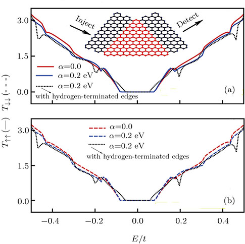
 | Fig. 1 (Color online) Spin-up and spin-down transmission probabilities as a function of the Fermi energy of the injected electrons for M = 10 and two values of α = 0 and 0.2 eV. Inset: Schematic representation of the channel for M = 10. |
Figure
If we consider the graphene nanorribbon with hydrogen-terminated edges, the length of the C-C bond in the edge shortens. So, this kind of geometric deformation causes increasing of the hopping parameter between two neighboring carbon atoms on the graphene nanoribbon edge.[30] By attention to dotted curves in Fig. 
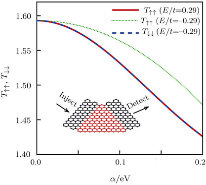
 | Fig. 2 (Color online) Spin-up and spin-down transmission probabilities as a function of the Rashba strength for M = 10 and two values of the Fermi energy. The solid and dotted lines show   |
Figure 

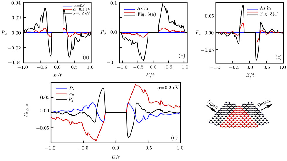
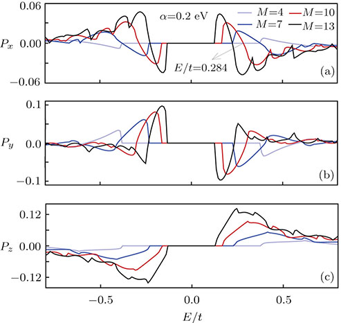
The effects of the RSOC on the components of the spin polarization are shown in Fig. 


In Fig. 


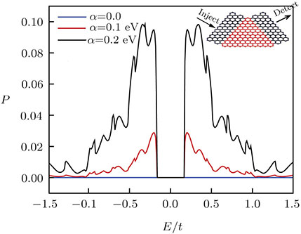
The spin-up transmission probability and the total spin polarization are shown in Fig. 
 | Fig. 3 (Color online) Components of the spin polarization as a function of the Fermi energy for M = 10 and various values of the Rashba strength in Figs. |
 | Fig. 4 (Color online) Total spin polarization versus the Fermi energy for M = 10 and various values of the Rashba strength. Inset: Schematic representation of the channel for M = 10. |
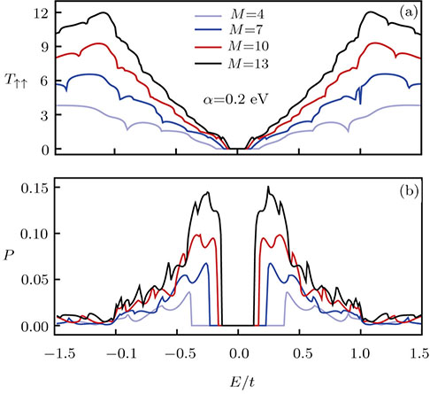 | Fig. 5 (Color online) Spin-up transmission probability and total spin polarization with respect to the Fermi energy for several sizes of the system at α = 0.2 eV. |
Figure 


 | Fig. 6 (Color online) Three components of the spin polarization with respect to the Fermi energy for several sizes of the system at α = 0.2 eV. |
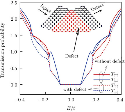
 | Fig. 7 Transmission probability in the absence (solid curves) and presence of defect (dashed curves) as a function of the Fermi energy of the injected electrons for M = 10 and α = 0.2 eV. Inset: Schematic representation of the channel with defect for M = 10. |
We have introduced a single defect as vacancy into this system and the result is plotted in Fig.
4 Conclusion
In this paper, the transmission probabilities and the spin polarization are investigated in the presence of RSOC via a gate voltage in the graphene nanoflake systems. The variation of the transmission probability is studied with respect to the Fermi energy of the electrons. This shows that out of the region of the zero energy, the transmission probability is growing by enhancement of the energy. Besides, the spin polarization increases with the enhancement of the Rashba strength and oscillates by variation of the energy. Also, the amplitudes of the peaks of the spin polarization decay to zero for all values of the Rashba strength. This indicates that the sign and the magnitude of the spin polarization can be controlled by tuning the gate voltage. Moreover, the effects of the size of the system on the transmission probability and the spin polarization is investigated. This shows that there is a control and manipulation of the spin filtration by means of the variation of the Rashba strength and the size of the system. The obtained results are applicable for electrical control on the spin transport in graphene-based nanodevices.
Reference
| [1] | |
| [2] | |
| [3] | |
| [4] | |
| [5] | |
| [6] | |
| [7] | |
| [8] | |
| [9] | |
| [10] | |
| [11] | |
| [12] | |
| [13] | |
| [14] | |
| [15] | |
| [16] | |
| [17] | |
| [18] | |
| [19] | |
| [20] | |
| [21] | |
| [22] | |
| [23] | |
| [24] | |
| [25] | |
| [26] | |
| [27] | |
| [28] | |
| [29] | |
| [30] |