近年来随着人类进军海洋步伐的加快,许多鱼类栖息地遭到严重破坏,海洋渔业资源急剧衰退,因此许多国家提出了海洋牧场的建设构想。根据《山东省人工鱼礁建设规划(2014—2020年)》,到2020年,山东省沿海区域将建设9大人工鱼礁带,40个人工鱼礁群。
人工鱼礁体作为海洋牧场的重要组成部分,是设置于预定海域的人工构筑物,可为鱼类创建适宜的繁育、生长、避敌场所,目前正受到越来越广泛的关注。人工鱼礁体投放入海后产生的上升流可引起海底营养物质卷起和扩散,礁体附近形成较理想的索饵区,能改善鱼群觅食条件。人工鱼礁流场效应是鱼礁体影响渔业资源增殖的重要因素。
M. Falcão等[1]通过对比人工鱼礁区和非鱼礁区营养盐通量和有机颗粒物的不同,研究了礁体影响营养盐通量和悬浮泥沙变化的水动力机制。
Jinho Woo等[2]通过数值模拟给出了包括透空立方体在内的24种不同形状人工鱼礁阻力系数值,结果表明阻力系数不随初始流速的变化而变化,但其受礁体迎流角度的影响较为显著。
Dongha Kim等[3]通过数值模拟研究了拱型、圆屋顶型等6类不同形状礁体尾涡长度与阻力系数的关系,表明礁体尾涡长度与阻力系数没有明显的线性关系。
唐衍力[4]通过水槽实验测得边长为0.15 m、开口比为0.22的有盖和无盖两种圆形开口鱼礁模型在不同来流速度、不同迎流角度时所受阻力,得到礁体阻力系数。
刘彦[5]通过数值模拟研究了中空正方体鱼礁单体及组合礁体在不同来流速度下的流场效应,计算了开口比为0.36的正方体人工鱼礁的抗滑移及抗倾覆安全系数。
赵云鹏等[6]建立三维数值波浪水槽研究波浪作用下三角型镂空人工鱼礁的受力情况,得到了三角型镂空鱼礁体阻力系数、惯性力系数随Kc数、Re数的变化情况。
由上述研究工作可知目前国内外学者对于人工鱼礁体的研究主要集中于单一开口比情况水流作用下礁体周围流场形态随海流流速、礁体形状、礁体迎流角度的变化情况及其生态效应方面,但是对于礁体流场效应、阻力系数、礁体受力及其稳定性随开口比的变化情况尚缺乏研究,已有研究工作[7]表明礁体开口比变化对上述流场特性有一定的影响。本文利用Fluent软件模拟方型人工鱼礁体水动力性能,旨在解决礁体流场效应、阻力系数、抗滑移及抗倾覆安全系数随开口比的变化问题,为实际礁体结构的设计提供参考。
1 模型 1.1 控制方程假设礁体附近的流动为粘性不可压缩流体的湍流运动,温度变化不大,能量方程可以忽略。
连续方程:
| $ \frac{{\partial {u_i}}}{{\partial {x_i}}} = 0。$ | (1) |
动量方程:
| $ \frac{{\partial {u_i}}}{{\partial t}} + {u_j}\frac{{\partial {u_i}}}{{\partial {x_j}}} = - \frac{1}{\rho }\frac{{\partial p}}{{\partial {x_i}}} + \frac{\partial }{{\partial {x_j}}}\left[ {\nu \frac{{\partial {u_i}}}{{\partial {x_j}}} - \overline {{{u'}_i}{{u'}_j}} } \right] + {f_i}。$ | (2) |
式中:ui(i=1,2,3)分别为x、y、z方向的雷诺平均速度;ρ为流体密度;p为压强;ν为运动粘性系数;fi为体积力。
1.2 湍流模型本文在计算粘性流体运动时采用RNG κ-ε两方程模型。此模型可以有效模拟分布较均匀、湍流结构较小的湍流流动[7],适合人工鱼礁体流场效应的研究。
湍动能κ方程:
| $ \frac{{\partial \left( {\rho \kappa } \right)}}{{\partial t}} + \frac{{\partial \left( {\rho \kappa {u_i}} \right)}}{{\partial {x_i}}} = \frac{\partial }{{\partial {x_j}}}\left( {{\alpha _\kappa }{\mu _{{\rm{eff}}}}\frac{{\partial \kappa }}{{\partial {x_j}}}} \right) + {G_\kappa } + \rho \varepsilon 。$ | (3) |
湍流耗散率ε方程:
| $ \frac{{\partial \left( {\rho \varepsilon } \right)}}{{\partial t}} + \frac{{\partial \left( {\rho \varepsilon {u_i}} \right)}}{{\partial {x_i}}} = \frac{\partial }{{\partial {x_j}}}\left( {{\alpha _\varepsilon }{\mu _{eff}}\frac{{\partial \varepsilon }}{{\partial {x_j}}}} \right) + \frac{{C_{1\varepsilon }^ * \varepsilon }}{\kappa }{G_\kappa } - {C_{2\varepsilon }}\rho \frac{{{\varepsilon ^2}}}{\kappa }。$ | (4) |
其中:
本文采用有限体积法离散控制方程,压力-速度耦合采用SIMPLEC算法,压力项处理采用标准差分格式,各方程空间离散均采用二阶迎风格式,计算残差值取10-5,采用非结构化网格,通过数值模拟方型礁体水动力特性,分析其流场效应、阻力系数随开口比的变化情况并计算礁体抗滑移及抗倾覆安全系数。
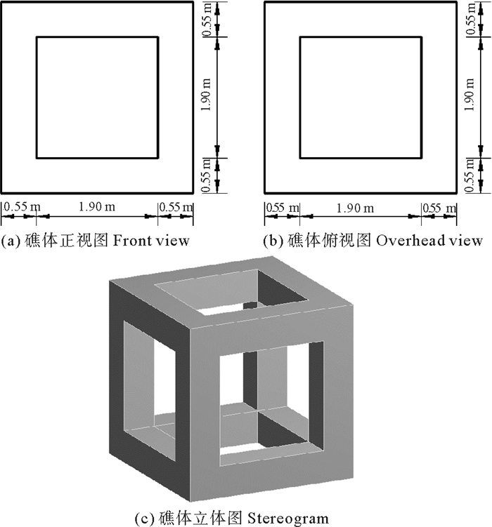
1.3 鱼礁结构及模拟计算区域4个侧面具有相同开口形式的礁体,其迎流面在垂直于水流方向上开口的投影面积与迎流面投影面积之比称为开口比(φ)[7]。图 1表示的是开口比为0.4的方型人工鱼礁体结构示意图。
|
图 1 开口比为0.4的方型人工鱼礁体结构 Fig. 1 The sketch of cubic artificial reef with 0.4 opening ratio |
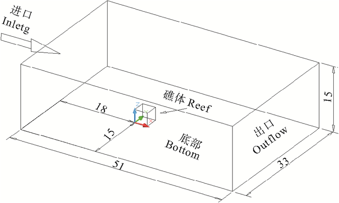
本文选取边长L为3 m、开口比φ分别为0、0.1、0.2、0.3、0.4、0.5、0.6的方形开口礁体,流速取为0.8 m/s,分析其周围流场形态、阻力系数随开口比的变化情况并计算其抗滑移、抗倾覆安全系数。仿真计算区域如图 2所示。
|
图 2 计算区域 Fig. 2 Computational domain |
文中所设定的初边界条件如下:
(1) 入口边界设置为速度入口边界条件(Velocity inlet),来流速度为0.8 m/s,设置边界上各方向的速度矢量分量,并给出边界上湍动能κ和湍动耗散率ε。
(2) 出口边界设置为自由出流边界条件(Outflow)。
(3) 计算域的两侧面设置为对称边界(Symmetry)。
(4) 计算域的顶面设置为具有与入口水流相同速度的可移动壁面,剪切力为零,底面和礁体表面设置为无滑移壁面(Wall)。
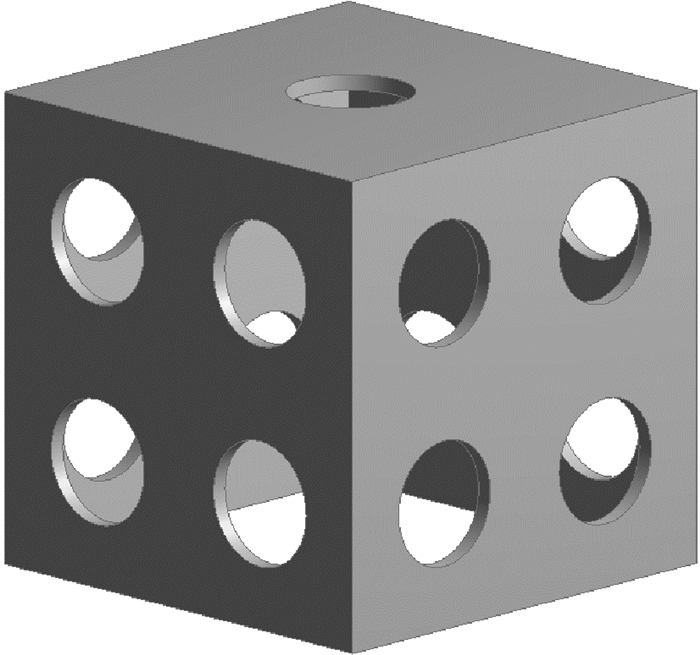
2 模型可靠性验证本文选择的是涡粘模型中的RNG κ-ε两方程模型,属于湍流非直接数值模拟方法中的Reynolds平均法(RANS),使用ANSYS Workbench 【Mesh】模块对计算域进行四面体单元非结构化网格划分。为了验证本文选择的湍流模型、参数设置、网格划分的准确性,选择唐衍力建立的边长为0.15 m,顶面有一个、每个侧面有四个直径均为0.04 m圆形开口,开口比为0.22的无底立方体人工鱼礁[4]进行数值模拟,如图 3所示。
|
图 3 圆形开口的人工鱼礁体模型 Fig. 3 Artificial reef model with circled cut-openings |
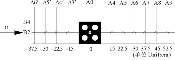
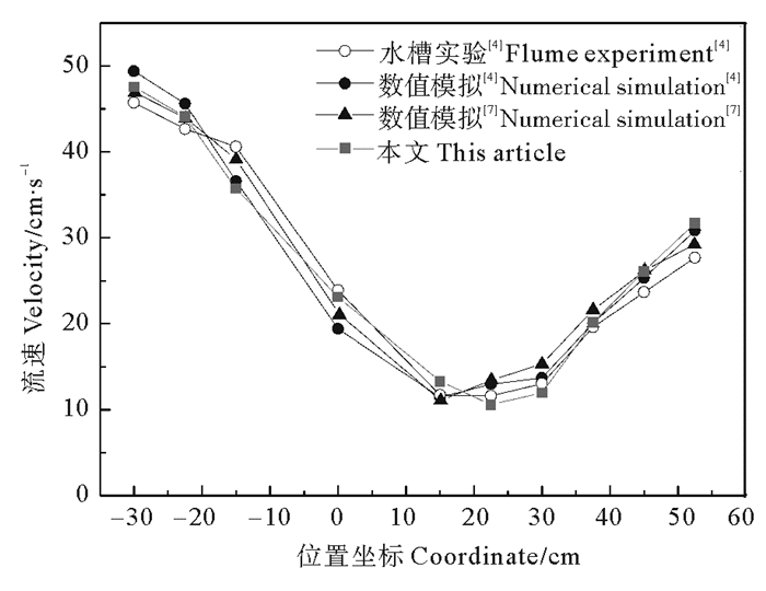
数值模拟时最大网格尺寸设置为0.025 m,礁体表面第一层边界层网格高度为0.002 m,增长率为1.1,共设置10层。设定来流速度为0.5 m/s,将模拟结果与已有学者进行的水槽实验和数值模拟结果进行对比,测点相对位置分布如图 4所示[4],结果如图 5及表 1所示。
|
图 4 测点相对位置分布示意图“○”—测点 Fig. 4 Sketch of relative distribution of measuring points"○"—measuring points |
|
图 5 测量点流速的实验值与模拟值的比较 Fig. 5 Comparison of the simulated and measured velocities of the measuring stations |
|
|
表 1 礁体阻力系数实验值与模拟值的比较 Table 1 Comparison of the simulated and measured Cd of the reef |
由对比结果可以看出,利用本文选择的数值模型模拟得到的礁体前后测点的流速及礁体阻力系数与其他学者通过物理模型实验和数值模拟得到的结果相近。本文利用Fluent软件模拟人工鱼礁水动力特性的研究方法是可行的。
3 不同开口比礁体水动力特性研究为了减小数值模拟过程中由于网格尺度所产生的误差,以边长为3 m、开口比为0.2的方型礁体为例,对计算域进行不同尺寸网格划分,网格收敛性验证以礁体阻力系数作为变量,结果如表 2所示。
|
|
表 2 不同网格尺寸模拟结果 Table 2 Simulation results with different gird sizes |
由表 2可以看出边长为3 m方型礁体的计算域最大网格尺寸为0.500 m时,礁体阻力系数受网格划分尺寸影响较小,网格收敛性较好,因此本文进行模拟时最大网格尺寸均设置为0.500 m,礁体表面第一层边界层网格高度为0.002 m,增长率为1.1,共设置10层。
基于上述数值模型,通过数值模拟研究边长为3 m、开口比为0~0.6之间7种礁体流场效应、阻力系数随开口比变化情况,计算不同开口比礁体抗滑移及抗倾覆安全系数。
3.1 礁体流场效应分析本研究中上升流区含义采用了黄远东等[9]提出的定义,即礁体附近竖直方向速度分量大于或等于5%来流速度的区域。上升流区范围越大,礁体的流场效应越显著,集鱼效果越好。
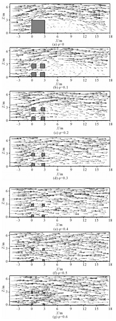
图 6表示的是来流速度为0.8 m/s时,边长为3 m的不同开口比礁体在y=1.5 m截面上的速度矢量分布。由图可以看出当开口比较小时,由于礁体的阻水作用,水流在礁体背流面后端形成速度很小、范围较大的漩涡,称为流向涡[10],此区域称为背涡区。当礁体开口比为0时,流向涡长度约为礁高的2.3倍,这与李晓磊等[10]得出的流向涡长度约为礁高的2.42倍相近,同时也与刘同渝[11]得出的流向涡长度为礁长的2~3倍相吻合;当礁体开口比为0.1时,流向涡长度略大,约为礁宽的3.7倍;当开口比大于0.3时,由于礁体开口透水作用增大,流经礁体中心至礁体后侧水流流量增大,因而观察不到明显的背涡区。
|
图 6 不同开口比礁体y=1.5 m平面速度矢量分布 Fig. 6 The velocity vector diagrams of reefs with different opening ratios in the plane of y=1.5 m |
表 3中Hmax/H表示礁体产生的上升流最大高度/礁高,Wmax/W表示上升流水平跨度/礁宽,Zmax/V表示上升流区竖直方向最大速度分量/来流速度。与开口比为0.1时相比,礁体开口比为0时产生的上升流相对高度及相对宽度均略小,这与黄远东等[12]得到的规律相同。当开口比大于0.1时,随着开口比的增大,来流受到礁体开口的分流增多,礁体上侧流管效应减弱,鱼礁引起的上升流最大高度、水平跨度及竖直方向最大速度分量均逐渐减小。
|
|
表 3 上升流特性参数随不同开口比的变化 Table 3 The upwelling current characteristic parameters changing with different opening ratios |
礁体阻力系数是表征人工鱼礁体稳定性的重要参数。已知礁体的阻力系数,其在水下抗滑移、抗倾覆安全系数便可通过计算求得。本文数值模拟中仅考虑礁体在来流速度不变时的受力情况,阻力系数可通过下式求得:
| $ {C_{\rm{d}}} = \frac{F}{{\frac{1}{2}\rho A{u^2}}}。$ | (5) |
式中:F为礁体沿水流方向受力(N);ρ为海水密度(kg/m3);A为礁体迎流面积(m2);u为水流速度(m/s)。
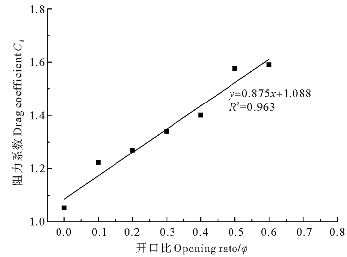
图 7给出了礁体阻力系数随其开口比的变化关系。在礁体开口比为0时,其阻力系数为1.052,与Jinho Woo等[2]通过数值模拟得到的1.069及Fox等[2]得到的1.05差异较小,与White和Young等[13]得到的立方型三维实体结构在Re≥104、垂直于水流放置时阻力系数为1.05~1.07相吻合。通过最小二乘法拟合得到边长为3 m、迎流面中心开口为方形的礁体阻力系数Cd与开口比φ的关系式(R2=0.963,P<0.01)为:
|
图 7 阻力系数与开口比的关系 Fig. 7 The relation between the drag coefficient and opening ratio |
| $ {C_{\rm{d}}} = 0.875\varphi + 1.088。$ | (6) |
可以看出在显著性水平α < 0.01时,该回归方程回归效果极显著。方型人工鱼礁开口比小于0.6时,随着礁体开口比的增大,礁体阻力系数逐渐增大。
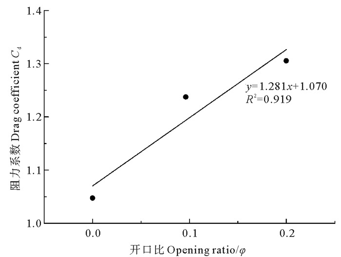
为了研究关系式(6)对于方型不同开口形状礁体阻力系数计算的适用性,选择圆形开口礁体进行数值模拟,礁体尺寸为10 cm×10 cm×10 cm,中空无底,壁厚为1.2 cm,每个侧面均开有直径为3.5 cm的圆孔,如图 8所示。将本文模拟结果与姜昭阳的实验结果[14]进行对比,如表 4所示。

|
图 8 礁体模型尺寸 Fig. 8 Dimensions of the reef model |
|
|
表 4 礁体阻力系数实测值与关系式计算值 Table 4 The experimental result and calculated value of Cd |
通过比较礁体阻力系数实测值与关系式计算值可以看出二者之间存在差异。利用实测阻力计算礁体阻力系数时,流速采用的是流速仪测量的平均值,与实验采集测力值时对应的瞬时流速不同;此外,由于水流的作用,在测力钢杆的后方会产生小的漩涡,引起钢杆的轻微振动,导致采集的测力值有波动,使得礁体受力测量值与计算值有差异。
|
图 9 圆形开口礁体阻力系数与开口比的关系 Fig. 9 The relation between the drag coefficient and opening ratio of circular opening reef |
如果考虑阻力值的数量级,关系式计算值与实测值结果较为一致,说明阻力系数与开口比的关系式可以应用于无底圆形开口礁体阻力系数的计算。
3.2 礁体稳定性计算日本学者中村充[5]研究了人工鱼礁体在波流共同作用时的受力情况,将波流速度看成是海流速度u0和波浪速度u1的叠加。
贾晓平等[15]认为人工鱼礁体在流速u下受到的力F可根据Morison方程计算:
| $ F = {F_{\rm{d}}} + {F_{{\rm{MA}}}} = \frac{1}{2}{C_{\rm{d}}}\rho A{u^2} + {C_{{\rm{MA}}}}\rho V\frac{{\partial u}}{{\partial t}}。$ | (7) |
式中Cd为阻力系数,CMA为附加质量系数,A为礁体迎流面积(m2),V为礁体实体体积(m3)。
F若取得最大值,需满足
| $ {x^4} + 2\alpha {x^3} + \left( {{\alpha ^2} + {\beta ^2} - 1} \right){x^2} - 2\alpha x - {\alpha ^2} = 0。$ | (8) |
| $ 2{x^2} + \alpha x - \beta \cdot \sqrt {1 - {x^2}} - 1 > 0。$ | (9) |
其中:
通过编写MATLAB程序实现牛顿迭代法求解式(3.3),可求得F最大时的sinθ和cosθ值,进而求得鱼礁体受力最大值Fmax。
本文选择日照近海某人工鱼礁区波浪参数[16]进行计算,见表 5。
|
|
表 5 日照近海某人工鱼礁区水文资料 Table 5 Hydrological data of an offshore artificial reef region in Rizhao |
人工鱼礁体投放于海底,不发生滑动的条件为礁体所受最大静摩擦力大于波流作用力,即抗滑移安全系数SF需满足下式:
| $ {S_{\rm{F}}} = \frac{{\left( {\sigma - \rho } \right)Vg \cdot \mu }}{{{F_{\max }}}} > 1。$ | (10) |
式中:σ为礁体材料的单位体积重量,对于混凝土人工鱼礁来说一般取2 000 kg/m3[17];μ为礁体与海底的静摩擦系数,取为0.5[17]。当SF大于1时,礁体不会发生滑移。为安全起见,SF应取1.2以上[18]。计算可得此海区波幅um为0.507 m/s,进而算得α为1.58。
从表 6中可以看出,当开口比较小时,方型礁体所受的最大波流作用力中,速度力所占比重较小,对波流作用力产生较大影响的是礁体所受的惯性力。随着开口比的增大,速度力占比逐渐增大,礁体所受最大波流作用力及抗滑移安全系数均逐渐减小,但礁体不会发生滑移,满足安全性要求。
|
|
表 6 不同开口比礁体受力及抗滑移安全系数 Table 6 The stress and safety factor against slippage of reefs with different opening ratios |
礁体在波流作用下不发生倾覆的条件为重力和浮力对倾覆中心的合力矩M1大于波流最大作用力矩M2。但由于一般人工鱼礁体内部结构较为复杂,为简化计算,假设最大波流作用力Fmax在礁体迎流面产生均布荷载
| $ {M_2} = \iint\limits_{{D_1}} {qz{\text{d}}y{\text{d}}z} + \iint\limits_{{D_2}} {qz{\text{d}}y{\text{d}}z} + \iint\limits_{{D_3}} {qz{\text{d}}y{\text{d}}z} + \iint\limits_{{D_4}} {qz{\text{d}}y{\text{d}}z}。$ | (11) |
礁体抗倾覆安全系数为:
| $ {S_{\rm{F}}} = \frac{{{M_1}}}{{{M_2}}} = \frac{{\left( {\sigma - \rho } \right)Vg{l_{\rm{w}}}}}{{{M_2}}}。$ | (12) |
式中:lw为倾覆中心到礁体重心的水平距离。当SF大于1时,礁体不会发生倾覆。为安全起见,SF应大于1.2。
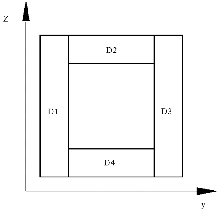
|
图 10 方型人工鱼礁体迎流面分块示意图 Fig. 10 Schematic diagram of incident flow area of cube artificial reef |
由表 7可以看出随着礁体开口比的增大,礁体迎流面均布荷载、波流最大作用力矩及抗倾覆安全系数均逐渐减小,但在日照近海人工鱼礁区海浪条件下,礁体不会发生倾覆,满足安全性要求,可以投入实际应用。
|
|
表 7 不同开口比礁体抗倾覆安全系数 Table 7 The safety factor against overturning of reefs with different opening ratios |
本文利用Fluent软件中的κ-ε湍流模型,模拟了不同开口立方型鱼礁体周围水流场,通过分析其流场效应、阻力系数、礁体稳定性随开口比变化的差异,得到了如下结论:
(1) 在开口比变化的情况下,人工鱼礁体流场效应等方面的水动力特性差异显著,而礁体稳定性的差异较小。
(2) 当开口比为0~0.2时,礁体后方流向涡和背涡区范围较大,礁体流场效应较明显,开口比为0.3~0.6时,礁体上侧流管效应较弱,后方没有明显的背涡区;礁体产生的上升流高度、水平跨度及竖直方向最大速度分量均随着礁体开口比的增大而减小。
(3) 当礁体开口比在0~0.6之间时,六个面中心均布有方形开口的立方型礁体的阻力系数与开口比间存在如下关系(R2=0.963,P < 0.01):Cd=0.875φ+1.088。
(4) 当开口比变化时,礁体稳定性安全系数有一定的差异。对于方形开口礁体,随着开口比的增大,速度力占比逐渐增大,礁体所受最大波流作用力、波流最大作用力矩、抗滑移和抗倾覆安全系数均逐渐减小,但礁体仍处于稳定状态。
| [1] |
Falcão M, Santos M N, Drago T, et al. Effect of artificial reefs (southern Portugal) on sediment-water transport of nutrients: Importance of the hydrodynamic regime[J]. Estuarine, Coastal and Shelf Science, 2009, 83(4): 451-459. DOI:10.1016/j.ecss.2009.04.028
(  0) 0) |
| [2] |
Woo J, Kim D, Yoon H S, et al. Characterizing Korean general artificial reefs by drag coefficients[J]. Ocean Engineering, 2014, 82: 105-114. DOI:10.1016/j.oceaneng.2014.02.025
(  0) 0) |
| [3] |
Kim D, Woo J, Yoon H S, et al. Wake lengths and structural responses of Korean general artificial reefs[J]. Ocean Engineering, 2014, 92: 83-91. DOI:10.1016/j.oceaneng.2014.09.040
(  0) 0) |
| [4] |
唐衍力.人工鱼礁水动力的实验研究与流场的数值模拟[D].青岛: 中国海洋大学, 2013. Tang Y L. Hydrodynamics Experiment of Artificial Reefs and Numerical Simulation of Flow Field[D]. Qingdao: Ocean University of China, 2013. (  0) 0) |
| [5] |
刘彦.人工鱼礁水动力特性数值与实验研究[D].大连: 大连理工大学, 2014. Liu Y. Numerical Simulations and Laboratory Experiments of Hydrodynamics for Artificial Reefs[D]. Dalian: Dalian University of Technology, 2014. (  0) 0) |
| [6] |
赵云鹏, 王晓鹏, 董国海. 波浪作用下三角型人工鱼礁水动力特性数值模拟与实验验证[J]. 海洋工程, 2015, 33(6): 52-61. Zhao Y P, Wang X P, Dong G H. Numerical simulation and experimental validation of hydrodynamic characteristics of submerged artificial reef in waves[J]. The Ocean Engineering, 2015, 33(6): 52-61. (  0) 0) |
| [7] |
邵万骏, 刘长根, 聂红涛, 等. 人工鱼礁的水动力学特性及流场效应分析[J]. 水动力学研究与进展, 2014, 29(5): 580-585. Shao W J, Liu C G, Nie H T, et al. Analysis of hydrodynamic characteristics and flow field around artificial reefs[J]. Chinese Journal of Hydrodynamics, 2014, 29(5): 580-585. (  0) 0) |
| [8] |
郑延璇.人工鱼礁流场效应与物理稳定性研究[D].青岛: 中国海洋大学, 2014. Zheng Y X. Flow Field Effect and Physical Stability of Artificial Reefs[D]. Qingdao: Ocean University of China, 2014. (  0) 0) |
| [9] |
黄远东, 姜剑伟, 赵树夫. 方型人工鱼礁周围水流运动的数值模拟研究[J]. 水资源与水工程学报, 2012, 23(3): 1-3. Huang Y D, Jiang J W, Zhao S F. Study on numerical model of water flows past a square artificial reef[J]. Journal of Water Resources and Water Engineering, 2012, 23(3): 1-3. (  0) 0) |
| [10] |
李晓磊, 栾曙光, 陈勇, 等. 立方体人工鱼礁背涡流的三维涡结构[J]. 大连海洋大学学报, 2012, 27(6): 572-577. Li X L, Luan S G, Chen Y, et al. The 3D vortex structure of cube artificial reef's wake vortex[J]. Journal of Dalian Ocean University, 2012, 27(6): 572-577. DOI:10.3969/j.issn.2095-1388.2012.06.016 (  0) 0) |
| [11] |
刘同渝. 人工鱼礁的流态效应[J]. 水产科技, 2003(6): 43-44. Liu T Y. Flow regime effect of artificial reefs[J]. Fisheries Science and Technology, 2003(6): 43-44. (  0) 0) |
| [12] |
黄远东, 龙催, 邓济通. 三棱柱型人工鱼礁绕流流场的CFD分析[J]. 水资源与水工程学报, 2013, 24(1): 1-4. Huang Y D, Long C, Deng J T. Analysis of water flow field based on CFD at a three-prism artificial reef[J]. Journal of Water Resources and Water Engineering, 2013, 24(1): 1-4. (  0) 0) |
| [13] |
Düzbastilar F O, Sentürk U. Determining the weights of two types of artificial reefs required to resist wave action in different water depths and bottom slopes[J]. Ocean Engineering, 2009, 36: 900-913. DOI:10.1016/j.oceaneng.2009.06.008
(  0) 0) |
| [14] |
姜昭阳.人工鱼礁水动力学与数值模拟研究[D].青岛: 中国海洋大学, 2009. Jiang Z Y. Numerical Simulation of Hydrodynamics for Artificial Reefs[D]. Qingdao: Ocean University of China, 2009. (  0) 0) |
| [15] |
贾晓平, 陈丕茂, 唐振朝, 等. 人工鱼礁关键技术研究与示范[M]. 北京: 海洋出版社, 2011. Jia X P, Chen P M, Tang Z C, et al. The Key Technologies Research and Demonstration on Artificial Reefs[M]. Beijing: China Ocean Press, 2011. (  0) 0) |
| [16] |
朱孔文, 孙满昌, 张硕, 等. 海州湾海洋牧场:人工鱼礁建设[M]. 北京: 中国农业出版社, 2011. Zhu K W, Sun M C, Zhang S, et al. Marine Ranching in Haizhou Bay: The Construction of Artificial Reefs[M]. Beijing: China Agriculture Press, 2011. (  0) 0) |
| [17] |
王晓鹏.波浪作用下人工鱼礁水动力特性的数值研究[D].大连: 大连理工大学, 2015. Wang X P. Numerical Simulation on the Investigation of Hydrodynamic Characteristics of Artificial Reef in Waves[D]. Dalian: Dalian University of Technology, 2015. (  0) 0) |
| [18] |
夏章英. 人工鱼礁工程学[M]. 北京: 海洋出版社, 2011. Xia Z Y. Artificial Reefs Engineering[M]. Beijing: China Ocean Press, 2011. (  0) 0) |
 2019, Vol. 49

