2) College of Hydrodynamic Engineering, Tianjin Research Institute for Water Transport Engineering, M.O.T, Tianjin 300456, China
With the exploitation of marine oil and gas resources gradually extending to deep-water fields, top-tensioned risers (TTRs) are no longer suitable. Risers in the form of a catenary have been used widely for subsea engineering owing to the advantages of strong adaptability to vessel motion and no pretensioning. When the flow passes over the riser, an unsteady wake is generated in the form of shedding vortices. The vortices alternately fall off from both sides of the riser, producing a periodically varying lift force in the cross-flow (CF) and in-line (IL) directions (Liu et al., 2020). As the vortex-shedding frequency approaches the natural frequency of the structure, the lock-in phenomenon occurs; that is, the vortex-induced vibration (VIV) responses of the riser strengthen remarkably, thus triggering serious fatigue damage.
Numerous works concerning the VIV performance of risers have been published in the past two decades. However, most of them focus on the TTRs' behaviors (Chaplin et al., 2005; Guo and Lou, 2008; Song et al., 2011; Thorsen et al., 2015; Low and Srinil, 2016; Kang et al., 2018; Gao et al., 2019; Liang and Lou, 2020). With the rapid development of long flexible risers used in ocean engineering, studies on the VIVs of slender risers with large deformation have gradually become important. Halse et al. (1999) investigated the VIV performance of a real catenary-type riser (CTR) subjected to uniform flows experimentally, and the results showed that a single mode dominated the VIV responses. Morooka and Tsukada (2013) conducted VIV tests on a CTR and found substantial traveling wave behaviors of the structural vibration. Zhu et al. (2019) conducted similar experiments on a CTR. Wang et al.(2014, 2017, 2018) performed laboratory tests on a truncated model of a CTR under vessel motion and uniform flows. The fatigue damage induced by the VIV responses of the CTR model subjected to external uniform flow and vessel motion is in the same order of magnitude. However, experimental methods have some limitations, such as model scale limit, expensive cost, difficult flow profile generation, and others (Gao et al., 2019). Therefore, studying the VIV performance of large aspect-ratio CTR using the numerical simulation method is more effective.
Computational fluid dynamic (CFD) methods can analyze the VIV problems of marine risers from the perspective of the flow field (Herfjord et al., 1999; Lucor et al., 2005; Fu et al., 2018; Martins and Avila, 2019). CFD is computationally intensive and time-consuming in the VIV calculation of slender structures. In contrast to the CFD method, the Van der Pol wake oscillator in the semiempirical method has been gradually used for the VIV responses of risers (Bishop and Hassan, 1964; Facchinetti et al., 2004). Srinil et al. (2009) combined the reduced-order model with the wake oscillator to predict the VIV responses of the CTR, and the results demonstrated the feasibility of this model on the VIV responses of the curved riser. Meng and Zhu (2015) numerically studied the effect of internal flow and top tension on the VIV responses of a CTR subjected to uniform flows using a hydrodynamic model. Li et al. (2021) analyzed the incident angle of external flow on the VIV responses of the CTR based on vector form intrinsic finite element (VFIFE) theory coupled with the wake oscillator model. Because the IL-direction VIV amplitude is small, an order of magnitude lower than the CF-direction one, the VIV responses in the CF direction are investigated considerably and emphatically at present, and those in the IL direction are ignored. The dominant frequency in the IL direction is normally twice that in the CF direction, so Wan and Duan (2017) stated that the VIV-induced fatigue damage in both directions may be in the same order of magnitude. Kang and Jia (2013) found that the IL-vibration VIV frequencies displayed a 'multifrequency' phenomenon at different natural frequencies, which made the trajectory exhibit various forms of motion. Additionally, IL-direction VIVs trigger an oscillatory characteristic of the flow fields, which in turn affects the VIV responses in the CF direction. Therefore, the vibration provided by the IL direction of the riser cannot be ignored.
Solving the governing equations of nonlinear vibration of the structure is effective for the conventional finite element method. However, the conversion of local coordinates into global coordinates is inevitable, resulting in long computing time. In this paper, a new numerical scheme, the VFIFE method, is used to establish a CTR model, which can avoid the coordinate transformation. Moreover, the stiffness matrix is needless, and no iterative solution is required in the VFIFE method, leading to a simple calculation for a complex structure. The current research shows that the VFIFE method has great potential in the field of marine riser research (Wu et al., 2020; Xu et al., 2021; Yu et al., 2022).
In summary, the VIV response of CTRs in both directions considering the coupling effect has not been exhaustively studied, and it still needs to be explored comprehensively. Therefore, this paper establishes a VIV response prediction model of a CTR in both directions based on VFIFE theory coupled with wake oscillators. The explicit central differential algorithm is applied to solve the governing equation and update the time integration. The paper is divided into five sections. Model theory is briefly described in Section 2. The model is validated thoroughly in Section 3. The VIV response results are studied in Section 4. Conclusions are drawn in Section 5.
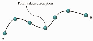
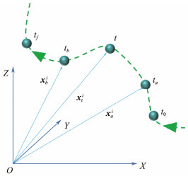
2 Model Description 2.1 Equation of Particle MotionVFIFE theory is used to simulate the CTR, where the riser system is composed of an infinite number of particles, as shown in Fig.1. Adjacent particles are connected by beam elements. The beam element is massless. The particle motion is divided into several independent time nodes (t0, t1, t2, ···, ta, tb, tf), and the motion path of particle i at any time period (ta ≤ t ≤ tb) is considered its path unit, as shown in Fig.2.
|
Fig. 1 Physical diagram of the particle. |
|
Fig. 2 Pathway unit. |
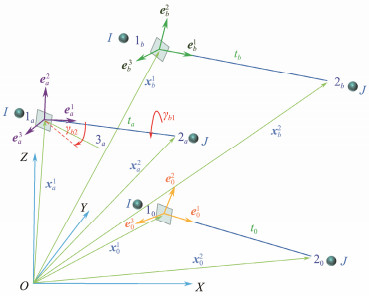
The axis of the riser is a time-varying curve under marine loadings, indicating that the axis direction of each beam element varies at different times. The particle position coordinates are calculated using a set of standard interpolation functions, and the principal coordinates of each beam element are constant. The principal coordinate system is established for pure deformation in Fig.3.
| $ \boldsymbol{u}_b^1=\boldsymbol{x}_b^1-\boldsymbol{x}_a^1, \boldsymbol{u}_b^2=\boldsymbol{x}_b^2-\boldsymbol{x}_a^2, $ | (1) |
| $ \boldsymbol{\beta}_b^1=\boldsymbol{\theta}_b^1-\boldsymbol{\theta}_a^1, \boldsymbol{\beta}_b^2=\boldsymbol{\theta}_b^2-\boldsymbol{\theta}_a^2, $ | (2) |
| $ \boldsymbol{e}_a^1=\frac{x_a^2-x_a^1}{\left|x_a^2-x_a^1\right|}, \quad \boldsymbol{e}_a^2=\frac{\boldsymbol{e}_{13} \times \boldsymbol{e}_a^1}{\left|\boldsymbol{e}_{13} \times \boldsymbol{e}_a^1\right|}, \quad \boldsymbol{e}_{13}=\frac{x_a^3-x_a^1}{\left|x_a^3-x_a^1\right|}, \quad \boldsymbol{e}_a^3=\boldsymbol{e}_a^1 \times \boldsymbol{e}_a^2 . $ | (3) |
|
Fig. 3 Schematic diagram of the main axis coordinate system. |
The rotation vector γb of the beam element in the time period tb − ta consists of two parts: γb1 is obtained by the beam element around its own axis. γb2 is determined by the rotation of the beam element from 1a − 2a to 1b - 2b at different moments. γb is expressed as γb = γb1 + γb2, γb1 =
The external force on the riser is converted into an equivalent concentrated force on the particles. Correspondingly, the governing equations for the motion of the J particle are established as follows:
| $ {m_J}\frac{{{{\text{d}}^2}}}{{{\text{d}}{t^2}}}\left[ {\begin{array}{*{20}{c}} {{x_J}} \\ {{y_J}} \\ {{z_J}} \end{array}} \right] = \left[ {\begin{array}{*{20}{c}} {{P_{Jx}}} \\ {{P_{Jy}}} \\ {{P_{Jz}}} \end{array}} \right] + {\sum\limits_{j = {\text{1}}}^n {\left({\left[ {\begin{array}{*{20}{c}} {{p_{jx}}} \\ {{p_{jy}}} \\ {{p_{jz}}} \end{array}} \right] + \left[ {\begin{array}{*{20}{c}} {{f_{jx}}} \\ {{f_{jy}}} \\ {{f_{jz}}} \end{array}} \right]} \right)} _J}, $ | (4) |
| $ {\left[ {\begin{array}{*{20}{c}} {{I_{xx}}}&{{I_{xy}}}&{{I_{xz}}} \\ {{I_{yx}}}&{{I_{yy}}}&{{I_{yz}}} \\ {{I_{zx}}}&{{I_{zy}}}&{{I_{zz}}} \end{array}} \right]_J}\frac{{{{\text{d}}^2}}}{{{\text{d}}{t^2}}}\left[ {\begin{array}{*{20}{c}} {{\theta _{Jx}}} \\ {{\theta _{Jy}}} \\ {{\theta _{Jz}}} \end{array}} \right] = \left[ {\begin{array}{*{20}{c}} {{Q_{Jx}}} \\ {{Q_{Jy}}} \\ {{Q_{Jz}}} \end{array}} \right] + {\sum\limits_{j = {\text{1}}}^n {\left({\left[ {\begin{array}{*{20}{c}} {{q_{jx}}} \\ {{q_{jy}}} \\ {{q_{jz}}} \end{array}} \right] + \left[ {\begin{array}{*{20}{c}} {{m_{jx}}} \\ {{m_{jy}}} \\ {{m_{jz}}} \end{array}} \right]} \right)} _J}, $ | (5) |
where XJ is the position vector of the particle J; θJ is the angular vector of the spatial direction; PJ and pj are the concentrated external force and equivalent external force, respectively; QJ and qj are the concentrated external moment and equivalent external moment, respectively; fj and mj are the internal force and internal moment provided by beam element; mJ denotes the total mass of particle J, which is expressed as follows:
| $ {m_J} = {\left({M + \sum\limits_{\alpha = {\text{1}}}^n {{m^\alpha }} } \right)_J} . $ | (6) |
The total mass of the riser is distributed equally among the particles:
| $ {m^1} = {m^2} = {l_a}({m_s} + {m_f})/2, $ | (7) |
where ms = ρs A, and mf = Ca ρf D2 π/4. The mass moment of inertia of the beam element relative to the main axis is expressed as follows:
| $ {\hat I_{\text{2}}} = \left({\frac{{\text{1}}}{{\text{2}}}{\rho _a}{l_a}{A_a}} \right)r_{\text{2}}^{\text{2}}, {\hat I_{\text{3}}} = \left({\frac{{\text{1}}}{{\text{2}}}{\rho _a}{l_a}{A_a}} \right)r_{\text{3}}^{\text{2}}, $ | (8) |
where la is the length of the beam element; Aa is the cross-sectional area of the beam element; ρa is the physical density of the beam element; r2 and r3 are the gyration radii. The matrix of inertia for the section is
| $ \boldsymbol{I}^j=\boldsymbol{\Omega}_u^{\mathrm{T}} \hat{\boldsymbol{I}}^j \boldsymbol{\Omega}_u, $ | (9) |
where Ωa is the conversion matrix from the global coordinate to the principal coordinate. Finally, the total inertia matrix of the particle J in the global coordinate system is calculated using the following equation:
| $ \boldsymbol{I}_J=\left(\boldsymbol{I}_m+\sum\limits_{\alpha=1}^n \boldsymbol{I}^\alpha\right)_J . $ | (10) |
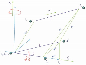
To address the pure deformation of the riser, the concept of virtual reverse motion is introduced in VFIFE theory. As shown in Fig.4, the beam element makes a virtual reverse motion, which includes translation and rotation. The displacement vectors of nodes 1 and 2 are shown in the following equation:
| $ \left\{\begin{array}{l} \boldsymbol{\eta}^1=\boldsymbol{u}^1-\boldsymbol{u}^1=0 \\ \boldsymbol{\eta}^2=\boldsymbol{u}^2+\left(-\boldsymbol{u}^1\right) \end{array},\right. $ | (11) |
|
Fig. 4 Reverse motion. |
where u1 and u2 are the translation vectors of the beam element.
The rotations of the rigid body are classified as axial rotation and translational rotation. Node 1 is taken as the reference point of rotation, and the rotation vector component in
| $ \hat{\beta}_1^1=\boldsymbol{\beta}_b^{\mathbf{l}} \cdot \boldsymbol{e}_a^1 . $ | (12) |
The other rotation component is the rotation of the beam element in time period t − ta and is shown as follows:
| $ \boldsymbol{\theta}_{t a}=\theta_{t a} \boldsymbol{e}_{t a}, $ | (13) |
where
The rotation vector γt can be expressed as follows:
| $ \boldsymbol{\gamma}_t=\hat{\beta}_1^1 \boldsymbol{e}_a^1+\theta_{t a} \boldsymbol{e}_{t a}. $ | (14) |
In the principal coordinate system, it is expressed as follows:
| $ \hat{\boldsymbol{\gamma}}_t=\mathbf{\Omega}_a \boldsymbol{\gamma}_t=\left[\begin{array}{lll} \hat{\beta}_1^1 & \hat{\theta}_{2 t} & \hat{\theta}_{3 t} \end{array}\right]^{\mathrm{T}}, \quad \boldsymbol{\Omega}_a=\left[\begin{array}{lll} \left(e_a^1\right)^{\mathrm{T}} & \left(e_a^2\right)^{\mathrm{T}} & \left(e_a^3\right)^{\mathrm{T}} \end{array}\right]^{\mathrm{T}} . $ | (15) |
As shown in Fig.4, the displacement of node 2 can be expressed as follows:
| $ \boldsymbol{\eta}^{2 d}=\hat{\Delta}_e \boldsymbol{e}_a^1, $ | (16) |
where
The angular displacements of nodes 1 and 2 are known as follows:
| $ \hat{\boldsymbol{\beta}}^j=\boldsymbol{\Omega}_u \boldsymbol{\beta}^j, j=1,2 . $ | (17) |
The amount of pure deformation occurring at unit nodes 1 and 2 in the principal coordinate system can be expressed as follows:
| $ \hat{\boldsymbol{\varphi}}^j=\hat{\boldsymbol{\beta}}^j-\hat{\boldsymbol{\gamma}}_t=\left[\begin{array}{c} \hat{\boldsymbol{\varphi}}_1^j \\ \hat{\varphi}_2^j \\ \hat{\varphi}_3^j \end{array}\right]=\left[\begin{array}{l} \hat{\beta}_1^j+\left(-\hat{\beta}_1^1\right) \\ \hat{\beta}_2^j+\left(-\hat{\theta}_{2 t}\right) \\ \hat{\beta}_3^j+\left(-\hat{\theta}_{3 t}\right) \end{array}\right], j=1,2 . $ | (18) |
In this study, the classical wake oscillator equation proposed by Facchinetti et al. (2004) is adopted:
| $ \frac{{{{\text{d}}^2}{q_j}}}{{{\text{d}}{t^2}}} + 2{\varepsilon _x}{\omega _{fj}}\left({q_j^2 - 1} \right)\frac{{{\text{d}}{q_j}}}{{{\text{d}}t}} + 4\omega _{fj}^2{q_j} = {A_x}\frac{{{{\text{d}}^2}{x_j}}}{{{\text{d}}{t^2}}}, $ | (19) |
| $ \frac{{{{\text{d}}^2}{p_j}}}{{{\text{d}}{t^2}}} + {\varepsilon _y}{\omega _{fj}}\left({p_j^2 - 1} \right)\frac{{{\text{d}}{p_j}}}{{{\text{d}}t}} + \omega _{fj}^2{p_j} = {A_y}\frac{{{{\text{d}}^2}{y_j}}}{{{\text{d}}{t^2}}}, $ | (20) |
where εx, εy, Ax and Ay are the parameters estimated according to the experiment. As reported in a study by Srinil and Zanganeh (2014), for flexible cylinders/pipes oscillating in the CF and IL directions, the values of Ay /εy or Ax /εx can be of the order of magnitude of 40 - 1920. In this work, the values of the four key parameters are set as εx = 0.05, εy = 0.04, Ax = 96, and Ay = 12.
qj and pj are the wake oscillator variables in both directions. ωfj is the vortex shedding frequency. In the analysis of VIV in the direction of CF and IL, the vortex shedding frequency ωfj fully considers the relative velocity between the IL direction motion and the flow fields
| $ \omega_{f j}=\frac{2 \pi S_t\left|U_c-\dot{x}\right|}{D}, $ |
instead of just considering the velocity of the fluid particles, and St is the Strouhal number.
Because the vibration frequency in the IL direction is twice that in the CF direction, the vibration frequency in the IL direction in Eq. (19) is 2ωfj, whereas the vibration frequency in the CF direction in Eq. (20) is ωfj.
The fluid force on space particle j is calculated by the following equation:
| $ {F_{Dj}} = \frac{1}{2}({C_{Dm}} + {C_D})\rho D{U_{jn}}^2, $ | (21) |
| $ {F_{Lj}} = \frac{1}{2}{C_L}\rho D{U_{jn}}^2, $ | (22) |
where CDm is the mean drag coefficient, CD is the fluctuating drag coefficient. and CL is the lift coefficient. CD =
Considering the iterative complexity and convergence difficulties of nonlinear problems, the explicit central difference method is adopted to solve the governing equations of the VIV responses of the CTR. The central differential solutions for position coordinates, the directional angle of particles, and the wake oscillator are as follows:
| $ \left[ {\begin{array}{*{20}{c}} {x_J^{n + 1}} \\ {y_J^{n + 1}} \\ {z_J^{n + 1}} \end{array}} \right] = 2{C_1}\left[ {\begin{array}{*{20}{c}} {x_J^n} \\ {y_J^n} \\ {z_J^n} \end{array}} \right] - {C_2}\left[ {\begin{array}{*{20}{c}} {x_J^{n - 1}} \\ {y_J^{n - 1}} \\ {z_J^{n - 1}} \end{array}} \right] + {C_1}{h^2}\left({\left[ {\begin{array}{*{20}{c}} {F_{Jx}^{{\text{ext}}}} \\ {F_{Jy}^{{\text{ext}}}} \\ {F_{Jz}^{{\text{ext}}}} \end{array}} \right] + \left[ {\begin{array}{*{20}{c}} {F_{Jx}^{{\text{int}}}} \\ {F_{Jy}^{{\text{int}}}} \\ {F_{Jz}^{{\text{int}}}} \end{array}} \right]} \right) / {m_J}, $ | (23) |
| $ \left[ {\begin{array}{*{20}{c}} {\theta _{Jx}^{n + 1}} \\ {\theta _{Jy}^{n + 1}} \\ {\theta _{Jz}^{n + 1}} \end{array}} \right] = 2{C_1}\left[ {\begin{array}{*{20}{c}} {\theta _{Jx}^n} \\ {\theta _{Jy}^n} \\ {\theta _{Jz}^n} \end{array}} \right] - {C_2}\left[ {\begin{array}{*{20}{c}} {\theta _{Jx}^{n - 1}} \\ {\theta _{Jy}^{n - 1}} \\ {\theta _{Jz}^{n - 1}} \end{array}} \right] + {C_1}{h^2}\left({\left[ {\begin{array}{*{20}{c}} {M_{Jx}^{{\text{ext}}}} \\ {M_{Jy}^{{\text{ext}}}} \\ {M_{Jz}^{{\text{ext}}}} \end{array}} \right] + \left[ {\begin{array}{*{20}{c}} {M_{Jx}^{{\text{int}}}} \\ {M_{Jy}^{{\text{int}}}} \\ {M_{Jz}^{{\text{int}}}} \end{array}} \right]} \right) / \left[ {\begin{array}{*{20}{c}} {{I_{Jx}}} \\ {{I_{Jy}}} \\ {{I_{Jz}}} \end{array}} \right], $ | (24) |
| $ q_j^{n + 1} = \frac{{\frac{{{A_x}{h^2}(F_J^{{\text{ext}}} + F_J^{{\text{int}}})}}{{D{m_J}}} + q_j^n(2 - 4\omega _{fj}^2h) - q_j^{n - 1}(1 - {\varepsilon _x}{\omega _{fj}}h({{(q_j^n)}^2} - 1))}}{{1 + {\varepsilon _x}{\omega _{fjn}}h({{(q_j^n)}^2} - 1)}}, $ | (25) |
| $ p_j^{n + 1} = \frac{{\frac{{{A_y}{h^2}(F_J^{{\text{ext}}} + F_J^{{\text{int}}})}}{{D{m_J}}} + p_j^n(2 - \omega _{fj}^2) - p_j^{n - 1}(1 - 0.5{\varepsilon _y}{\omega _{fj}}h({{(q_j^n)}^2} - 1))}}{{1 + 0.5{\varepsilon _y}{\omega _{fj}}h({{(p_j^n)}^2} - 1)}}, $ | (26) |
where h is the time step. C1 and C2 are the damped compound terms expressed as C1 = 1/(1 + ξh/2) and C2 = C1/(1 − ξh/2), respectively. ξ is the damping coefficient of the structure.
Before the examination of the structural VIV responses, the accuracy and applicability of the proposed numerical scheme should be strictly verified. In this paper, VIV tests on a small-scale model of a flexible riser conducted by Zhu et al. (2016) and a numerical simulation result of VIV responses of a cylinder based on the CFD method by Yamamoto et al. (2004) are selected as references. The key parameters are set according to the literature.
Fig.5 presents the VIV displacement distributions along the span using the proposed theory compared with the experimental results given by Zhu et al. (2016). The VIV responses calculated by the wake oscillator model agree with the reference results, particularly in Fig.5. A small difference can be clearly observed, namely, the VIV displacement at z/L = 0.3 obtained by the wake oscillator model is lower than that from the reference, and the relative error between the calculated results using the proposed model and the experimental results of Zhu et al. (2016) is lower than 15%, which could be due to the different damping coefficients. In addition, the result is attributed to the possibly uncaptured nonlinear physics (such as splashing-over). However, the correlation between the predicted and published results is reasonable, which also indicates the accuracy and applicability of the proposed numerical scheme in calculating the VIV responses of a CTR.

|
Fig. 5 Comparison of the CF-direction VIV displacement distributions along the span of the small-scale flexible riser under shear flows. (a), Umax = 0.036 m s−1; (b), Umax = 0.067 m s−1; (c), Umax = 0.133 m s−1; and (d), Umax = 0.151 m s−1. |
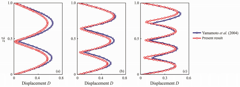
To verify further the accuracy of the proposed model in calculating the coupled VIV responses of marine risers in both directions, the calculated result based on the wake model is compared with those presented in Yamamoto et al. (2004) using the CFD methods, as shown in Fig.6. The displacement distributions of the cylinder in the CF direction calculated based on the two methods are consistent; despite a few differences, the relative error between the proposed model and Yamamoto et al. (2004) is lower than 8%. Furthermore, the reason for the difference could be the different damping coefficients. Overall, the proposed model is applicative in predicting the coupled VIV responses.
|
Fig. 6 Comparison of VIV displacement distributions along the span of the riser in the CF direction under uniform flows. (a), U = 0.38 m s−1; (b), U = 0.54 m s−1; and (c), U = 0.85 m s−1. |
The coupled VIV responses of a CTR in the CF and IL directions, including displacement distribution, dominant frequency, standing wave behavior, traveling wave behavior, motion trajectory, and energy transfer, are investigated systematically under the effects of uniform flows with different flow velocities of with U = 0.25, 0.35, 0.45, and 0.55 m s−1. The research in this section aims to provide scientific support for the design, operation, and maintenance of catenary-type flexible risers. The main parameters of the CTR model are listed in Table 1.
|
|
Table 1 Parameters of the CTR |
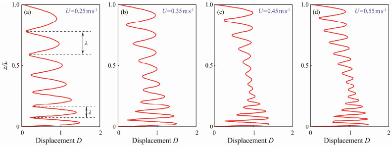
Fig.7 presents the VIV displacement distributions of the CTR in the CF direction under uniform flows with U = 0.25, 0.35, 0.45, and 0.55 m s−1. Prominent multimode characteristics occur in the VIV responses of the riser under the excitation of uniform flows, and with the increase of the external velocity, higher-order modes continuously participate in the CF-direction VIV response of the structure. The dimensionless wavelength λ decreases gradually from the top end to the bottom end along the span of the riser, which is different from the dimensionless wavelength of TTRs subjected to uniform flows (Gao et al., 2019). The increased flow velocity has a slight effect on this unique characteristic, indicating that structural nonlinearity triggers the nonuniform distribution of the dimensionless wavelength. Moreover, the maximum amplitude only varies slightly with increasing velocity, and the position corresponding to the maximum is still at the bottom part of the riser. The VIV amplitudes remain high, which is because the normal component of the external flow is larger. The higher tension at the top part of the riser also poses a limitation on the development of VIV performance, indicating the tension has important effects on the VIV amplitudes of the CTR. Additionally, the fluctuation characteristic of the VIV displacement distributions is remarkably reduced in the range of z/L = 0.50 - 0.75.
|
Fig. 7 RMS displacement distributions of VIV responses in the CF direction under uniform flows with U = 0.25, 0.35, 0.45, and 0.55 m s−1. |
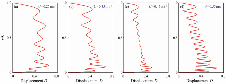
Fig.8 presents the VIV displacement distributions of the CTR in the IL direction under uniform flows with U = 0.25, 0.35, 0.45, and 0.55 m s−1. The VIV performance in the IL direction exhibits properties similar to those in the CF direction. For example, multimode responses participate in the structural vibration, the maximum amplitudes occur near the bottom region of the CTR, higher-order modes are involved in the VIV behaviors, and the dimensionless wavelength λ varies along the span of the CTR. In addition, the IL-direction amplitude is dramatically lower than the CF-direction one, which is similar to the VIV responses of top-tensioned risers. Higher-order modes usually appear in the IL-direction VIV responses of the top-tensioned riser than the CF-direction ones. However, the same phenomenon is hardly seen in the VIV performance of the CTR. This outcome is closely related to the coupled velocity and the structural characteristic, of course. Fig.8(c) presents that the displacement fluctuation in the lower parts of the riser nearly disappears, which may be due to the high-order modal conversion at a flow velocity of 0.45 m s−1, and the vibration response is unstable.
|
Fig. 8 RMS displacement distributions of VIV responses in the IL direction under uniform flows. |
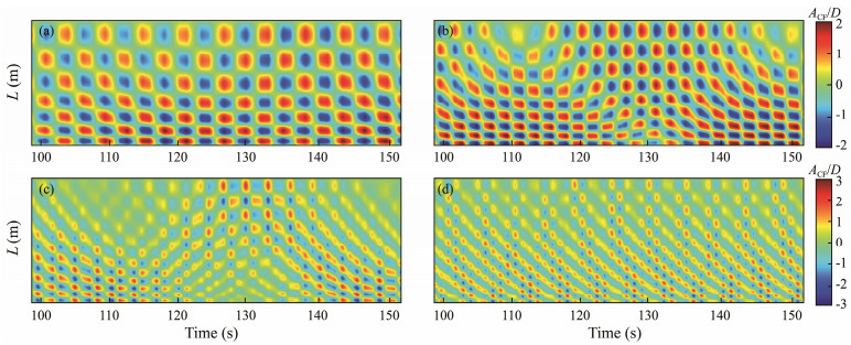
Fig.9 presents the spatiotemporal distributions of VIV displacements of the CTR in the CF direction under uniform flows with U = 0.25, 0.35, 0.45, and 0.55 m s−1. The standing wave behavior dominates the structural vibration at U = 0.25 and 0.35 m s−1, particularly in the upper part of the riser, but slight traveling wave characteristics are observed in the bottom region of the riser. This result indicates that the VIV response in the bottom parts is more sensitive to the external velocity, possibly because the bottom tension of the riser is much smaller than that of the top despite the lower normal component of external flow velocity. As the flow velocity grows continuously, traveling wave behaviors become increasingly evident, and the structural vibration exhibits a mixture of traveling wave and standing wave performance. The standing wave still dominates the VIV response of the CTR in the top region, which is due to the restriction of the top hinge and its high tension.
|
Fig. 9 Spatiotemporal distributions of VIV displacements of the CTR in the CF direction under uniform flows with U = 0.25, 0.35, 0.45, and 0.55 m s−1. |
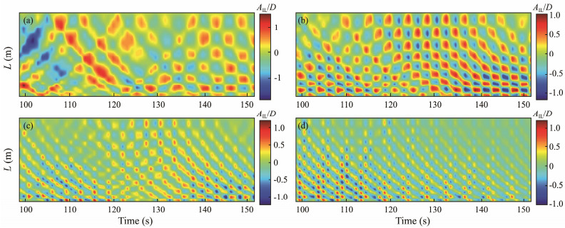
Fig.10 presents spatiotemporal distributions of VIV displacements of the CTR in the IL direction under uniform flows with U = 0.25, 0.35, 0.45, and 0.55 m s−1. Traveling wave characteristics are clear in the structural VIV responses. However, the standing wave property does not disappear, indicating that the structural vibration in the IL direction also behaves the mixed characteristic of traveling wave and standing wave. The traveling wave of the VIV performance fades in the period of 120 - 135 s, while the standing wave behavior is substantial. This result could be due to the vibration instability.
|
Fig. 10 Spatiotemporal distributions of VIV displacements of the CTR in the IL direction under uniform flows with U = 0.25, 0.35, 0.45, and 0.55 m s−1. |
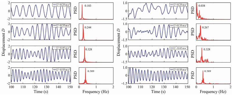
Fig.11 presents the time series of VIV displacement and frequency spectrum at z/L = 0.5 under different flow velocities with U = 0.25, 0.35, 0.45, and 0.55 m s−1. The dominant frequencies in the CF and IL directions at z/L = 0.5 increase with the increase of the external flow velocities, and a slightly lower frequency component and a slightly higher frequency component are vaguely captured in the CF direction. This result indicates that the CF-direction VIV responses are unstable. However, the IL-direction VIV responses demonstrate a trend opposite to that of the CF-direction ones. For example, the VIV performance in the IL direction transforms from instability to stability, and sub-frequency components gradually disappear. A possible reason is that at high flow velocity, the relative velocity induced by structural vibration has a slight influence on the external velocity. The dominant frequency in the IL direction is nearly the same as that in the CF direction, while a substantial dual-frequency relationship between the dominant frequencies of top-tensioned risers in the IL and CF directions can be clearly captured. The main reason for this difference is also the asymmetry of vibration modes induced by the geometric nonlinearity of the structure.
|
Fig. 11 Time series of VIV displacement and frequency spectrum at z/L = 0.5 under different flow velocities with U = 0.25, 0.35, 0.45, and 0.55 m s−1. |
Figs. 12 - 15 present the oscillation orbits of the VIV responses of the CTR under uniform flows of U = 0.25, 0.35, 0.45, and 0.55 m s−1 at different positions. All the VIV trajectories exhibit a common elliptical orbit, which is due to the nearly equal relationship between the IL- and CF-direction dominant frequencies. However, some of the chaotic tracks can be observed, where figure-eight shapes are faintly visible, especially at the external flow velocity of 0.25 m s−1. This outcome is because the VIV frequency spectrum in the IL direction may have a relatively high-frequency component at some locations, but it is not strictly twice the CF-direction dominant frequency. With the increase of the flow velocity, the oscillation orbits of the CTR are stable, and the different inclination direction of the elliptical orbit is due to the dissimilar phase between the CF- and IL-direction VIV responses.

|
Fig. 12 Oscillation orbits of VIV responses of the CTR under a uniform flow of 0.25 m s−1. |

|
Fig. 13 Oscillation orbits of the VIV responses of the CTR under a uniform flow of 0.35 m s−1. |

|
Fig. 14 Oscillation orbits of the VIV responses of the CTR under a uniform flow of 0.45 m s−1. |

|
Fig. 15 Oscillation orbits of the VIV responses of the CTR under a uniform flow of 0.55 m s−1. |
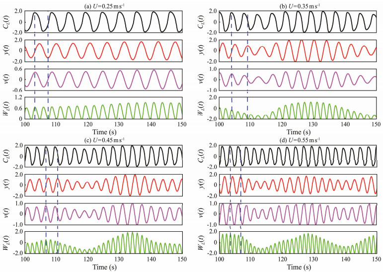
Fig.16 presents the instantaneous lift force coefficient, structural displacement, structural velocity, and transferred energy at z/L = 0.5 with four different flow velocities. The first three concepts are easy to understand, and the flow-solid energy transfer is introduced by the equation proposed by Newman and Karniadakis (1997):
| $ {W_L}(z, t) = {C_L}(z, t) \cdot v(z, t) = 0.5 \cdot {C_{L0}} \cdot p(z, t) \cdot \partial y(z, t)/\partial t . $ | (27) |
|
Fig. 16 Instantaneous lift force coefficient, structural displacement, structural velocity, and transferred energy at z/L = 0.5 with different flow velocities. (a), U = 0.25 m s−1; (b), U = 0.35 m s−1; (c), U = 0.45 m s−1; and (d), U = 0.55 m s−1. |
Fig.16 shows that when the lift force coefficient is zero, the structural displacement reaches its maximum value, and the lift force coefficient has its minimum value with nearly no structural displacement. The peaks of the energy transfer are about 1.6, 2.0, 3.5, and 3.5, indicating that the transferred energy increases with the increase of the flow velocity. When the energy value is positive, the flow fluids transfer energy to the riser structure, leading to vibration intensification; otherwise, the riser transfers energy to the flow field, resulting in decreased VIV responses. According to the equation, when the lift force coefficient is positive and structural velocity is negative, the transferred energy is negative. However, the negative energy region is not noticeable under the excitation of the uniform flow. This finding is because the phase of the displacement is always lagging the velocity by π/2, causing the lift force coefficient to be nearly in phase with the structural velocity, which is similar to the results of the vertical riser (Gao et al., 2019).
5 ConclusionsThe VIV responses of a CTR subjected to uniform flows by using the VFIFE scheme with wake oscillator equations are investigated thoroughly. The VIV response characteristics, including displacement, frequency, standing wave, traveling wave, and energy transfers from fluid flows to the riser, are determined and systematically discussed. The following conclusions are drawn:
1) The multimode characteristics are very substantial under the effect of uniform flows, and higher-order modes continuously participate in the CF-direction VIV response of the structure by increasing the flow velocity. The VIV displacements at the top and bottom parts of the riser are apparent but only vary slightly with the flow velocity. The maximum RMS displacements in the CF and IL directions are 1.45 D and 0.624 D, respectively.
2) As the external flow velocity increases, the VIV responses of the CTR change from a predominantly standing wave behavior to a mixed mode of the standing wave and traveling wave behaviors. With the increase of flow velocities, the vibration modes also gradually increase, and the corresponding modes are 7, 9, 12, and 14. Compared with the CF-direction VIV responses, the traveling wave phenomenon in the IL direction is more noticeable. However, the VIV performance at the top region of the riser is still dominated by the standing wave characteristic due to the influence of the high tension and joint restriction.
3) The double relationship of the dominant frequency in the CF and IL directions is hardly captured due to the structural nonlinearity characteristic, which leads to the shape of an inclined elliptical orbit for the vibration trajectory. The CF-direction VIV responses are unstable, the IL-direction VIV responses transform from instability to stability, and sub-frequency components gradually disappear. A figure-8 shape appears vaguely at several locations due to the higher frequency components in the IL direction.
4) Under the flow velocities of 0.25, 0.35, 0.45, and 0.55 m s−1, the peaks of energy are about 1.6, 2, 3.5, and 3.5, respectively, indicating that the transferred energy increases with the increase of the flow velocity. Because the phase of the displacement is always lagging the velocity by π/2, the transferred energy calculated by Eq. (23) is positive. This outcome indicates that the energy always flows from the flow fields into the structure. With the increase of the external velocity, the energy transfer gradually becomes unstable.
AcknowledgementsThis research was supported by the National Key R & D Program of China (No. 2022YFB2602800), the National Science Foundation of China (No. 51979257), the Basic Funding of the Central Public Research Institutes (Nos. TKS20210101, TKS20220103, TKS20230102), the Fundamental Research Funds for the Central Universities (No. 202413018), the postdoctoral project of Shandong (No. SDCX-ZG-202400218), and the postdoctoral project of Qingdao (No. QDBSH20240101013).
Bishop, R. E. D., and Hassan, A. Y., 1964. The lift and drag forces on a circular cylinder oscillating in a flowing fluid. Mathematical Physical and Engineering Sciences, 277(1368): 51-75. (  0) 0) |
Chaplin, J. R., Bearman, P. W., Cheng, Y., and Fontaine, E., 2005. Blind predictions of laboratory measurements of vortex-induced vibrations of a tension riser. Journal of Fluids and Structures, 21(1): 25-40. DOI:10.1016/j.jfluidstructs.2005.05.016 (  0) 0) |
Facchinetti, M. L., De, L. E., and Biolley, F., 2004. Coupling of structure and wake oscillators in vortex-induced vibrations. Journal of Fluids and Structures, 19(2): 123-140. DOI:10.1016/j.jfluidstructs.2003.12.004 (  0) 0) |
Fu, B. W., Zou, L., and Wan, D. C., 2018. Numerical study of vortex-induced vibrations of a flexible cylinder in an oscillatory flow. Journal of Fluids and Structures, 77: 170-181. DOI:10.1016/j.jfluidstructs.2017.12.006 (  0) 0) |
Gao, Y., Zou, L., Zong, Z., Takagi, S., and Kang, Y., 2019. Numerical prediction of vortex-induced vibrations of a long flexible cylinder in uniform and linear shear flows using a wake oscillator model. Ocean Engineering, 171: 157-171. DOI:10.1016/j.oceaneng.2018.10.044 (  0) 0) |
Guo, H. Y., and Lou, M., 2008. Effect of internal flow on vortex-induced vibration of risers. Journal of Fluids and Structures, 24(4): 496-504. DOI:10.1016/j.jfluidstructs.2007.10.002 (  0) 0) |
Halse, K. H., Mo, K., and Lie, H., 1999. Vortex induced vibration of a catenary riser. Third International Symposium on Cable Dynamics. Trondheim: 103-110. (  0) 0) |
Herfjord, K. K., Drange, S. O., and Kvamsdal, T. T., 1999. Assessment of vortex-induced vibrations on deepwater risers by considering fluid-structure interaction. Journal of Offshore Mechanics and Arctic Engineering, 121(4): 207-212. DOI:10.1115/1.2829569 (  0) 0) |
Kang, Z., and Jia, L. S., 2013. An experiment study of a cylinder's two degree of freedom VIV trajectories. Ocean Engineering, 70: 129-140. DOI:10.1016/j.oceaneng.2013.05.033 (  0) 0) |
Kang, Z., Zhang, C., and Chang, R., 2018. A higher-order nonlinear oscillator model for coupled cross-flow and in-line VIV of a circular cylinder. Ships and Offshore Structures, 13(5): 488-503. DOI:10.1080/17445302.2018.1426431 (  0) 0) |
Li, X. M., Chen, D. P., Gu, H. L., and Bai, F. T., 2021. Three-dimensional vortex-induced vibration analysis of catenary-type risers under flow with different incident angles. Ocean Engineering, 240: 109978. DOI:10.1016/j.oceaneng.2021.109978 (  0) 0) |
Liang, W. X., and Lou, M., 2020. Numerical simulation of vortex-induced vibration of a marine riser with a multiphase internal flow considering hydrate phase transition. Ocean Engineering, 216: 107758. DOI:10.1016/j.oceaneng.2020.107758 (  0) 0) |
Liu, G. J., Li, H. Y., Qiu, Z. Z., Leng, D. X., and Li, Z. X., 2020. A mini review of recent progress on vortex-induced vibrations of marine risers. Ocean Engineering, 195: 106704. DOI:10.1016/j.oceaneng.2019.106704 (  0) 0) |
Low, Y. M., and Srinil, N., 2016. VIV fatigue reliability analysis of marine risers with uncertainties in the wake oscillator model. Engineering Structures, 106: 96-108. DOI:10.1016/j.engstruct.2015.10.004 (  0) 0) |
Lucor, D., Foo, J., and Karniadakis, G. E., 2005. Vortex mode selection of a rigid cylinder subject to VIV at low mass-damping. Journal of Fluids and Structures, 20: 483-503. DOI:10.1016/j.jfluidstructs.2005.02.002 (  0) 0) |
Martins, F. A. C., and Avila, J. P. J., 2019. Three-dimensional CFD analysis of damping effects on vortex-induced vibrations of 2DOF elastically-mounted circular cylinders. Marine structures, 65(1): 12-31. (  0) 0) |
Meng, D., and Zhu, C. J., 2015. Synergetic analysis and possible control of vortex-induced vibrations in a fluid-conveying steel catenary riser. Journal of Ocean University of China, 14(2): 245-254. DOI:10.1007/s11802-015-2339-0 (  0) 0) |
Morooka, C. K., and Tsukada, R. I., 2013. Experiments with a steel catenary riser model in a towing tank. Applied Ocean Research, 43(1): 244-255. (  0) 0) |
Newman, D. J., and Karniadakis, G. E., 1997. A direct numerical simulation study of flow past a freely vibrating cable. Journal of Fluid Mechanics, 344: 95-136. DOI:10.1017/S002211209700582X (  0) 0) |
Song, J. N., Lu, L., Teng, B., and Park, H., 2011. Laboratory tests of vortex-induced vibrations of a long flexible riser pipe subjected to uniform flow. Ocean Engineering, 38(11): 1308-1322. (  0) 0) |
Srinil, N., and Zanganeh, H., 2014. Characterization of variable hydrodynamic coefficients and maximum responses in two-dimensional vortex-induced vibrations with dual resonances. Journal of Vibration and Acoustics, 136(5): 05101. (  0) 0) |
Srinil, N., Wiercigroch, M., and O'Brien, P., 2009. Reduced-order modeling of vortex-induced vibration of catenary riser. Ocean Engineering, 36(17): 1404-1414. (  0) 0) |
Thorsen, M. J., Sævik, S., and Larsen, C. M., 2015. Fatigue damage from time domain simulation of combined in-line and cross-flow vortex-induced vibrations. Marine Structures, 41: 200-222. DOI:10.1016/j.marstruc.2015.02.005 (  0) 0) |
Wan, D. C., and Duan, M. Y., 2017. A recent review of numerical studies on vortex-induced vibrations of long slender flexible risers in deep sea. Chinese Quarterly of Mechanics, 38(2): 179. (  0) 0) |
Wang, J. G., Fu, S. X., and Baarholm, R., 2018. Evaluation of vortex-induced vibration of a steel catenary riser in steady current and vessel motion-induced oscillatory current. Journal of Fluids and Structures, 82: 412-431. DOI:10.1016/j.jfluidstructs.2018.07.018 (  0) 0) |
Wang, J. G., Fu, S. X., and Larsen, C. M., 2017. Dominant parameters for vortex-induced vibration of a steel catenary riser under vessel motion. Ocean Engineering, 136: 260-271. DOI:10.1016/j.oceaneng.2017.03.015 (  0) 0) |
Wang, J. G., Fu, S. X., Baarholm, R., Wu, J., and Larsen, C. M., 2014. Fatigue damage of a steel catenary riser from vortex-induced vibration caused by vessel motions. Marine Structures, 39: 131-156. DOI:10.1016/j.marstruc.2014.07.002 (  0) 0) |
Wu, H., Zeng, X. H., Xiao, J. Y., and Yu, Y., 2020. Vector form intrinsic finite-element analysis of static and dynamic behavior of deep-sea flexible pipe. International Journal of Naval Architecture and Ocean Engineering, 12: 376-386. DOI:10.1016/j.ijnaoe.2020.04.003 (  0) 0) |
Xu, P., Du, Z. X., Huang, F. Y., and Javanmardi, A., 2021. Numerical simulation of deepwater S-lay and J-lay pipeline using vector form intrinsic finite element method. Ocean Engineering, 234: 109039. DOI:10.1016/j.oceaneng.2021.109039 (  0) 0) |
Yamamoto, C. T., Meneghini, J. R., Saltara, F., Fregonesi, R. A., and Ferrari, J. A., 2004. Numerical simulations of vortex-induced vibration on flexible cylinders. Journal of Fluids and Structures, 19(4): 467-489. DOI:10.1016/j.jfluidstructs.2004.01.004 (  0) 0) |
Yu, Y., Xu, S. B., Yu, J. X, and Xu, W. P., 2022. Influence of seabed trench on the structural behavior of steel catenary riser using the vector form intrinsic finite element method. Ocean Engineering, 251: 110963. DOI:10.1016/j.oceaneng.2022.110963 (  0) 0) |
Zhu, H. J., Lin, P. Z., and Gao, Y., 2019. Vortex-induced vibration and mode transition of a curved flexible free-hanging cylinder in exponential shear flows. Journal of Fluids and Structures, 84: 56-76. DOI:10.1016/j.jfluidstructs.2018.10.009 (  0) 0) |
Zhu, H. J., Lin, P. Z., and Yao, J., 2016. An experimental investigation of vortex-induced vibration of a curved flexible pipe in shear flows. Ocean Engineering, 121: 62-75. DOI:10.1016/j.oceaneng.2016.05.025 (  0) 0) |
 2024, Vol. 23


