 2020, Vol. 19


2) National Deep Sea Center, Qingdao 266237, China;
3) Institute of Marine Science and Technology, Shandong University, Qingdao 266237, China;
4) Science and Technology on Underwater Vehicle Laboratory, Harbin Engineering University, Harbin 150001, China
The hadal zone (6 – 11 km) is one of the least-understood habitats on Earth due to its extreme conditions such as high pressure, darkness, and low temperature (Wolff, 1970; Clemens and Tiedemann, 1997; Zachos et al., 2001). The zone features rich biodiversity and abundance, but our knowledge of the ecosystem is minimal due to technical limitations.
Recently, there have been new developments in underwater vehicle technology, such as human occupied vehicles (Liu, 2014); remotely operated vehicles (Yoshida et al., 2007); autonomous underwater vehicles; (Bowen et al., 2008); and landers (Jamieson et al., 2009), as shown in Fig.1.

|
Fig. 1 Jiaolong manned submersible and Hadal Lander A. |
In 2016, China's submersible and hadal lander completed the 37th Dayang Cruise in the Mariana Trench. The diving area was along the southern slope of the Challenger Deep where the seafloor is approximately 6300 – 8300 m deep. During this expedition, the submersible was deployed on nine dives during which it made several discoveries (Cui et al., 2017; Gao et al., 2017). However, the ability to sample sediment below 11000 m is limited, and instruments capable of collecting samples at full ocean depths need to be urgently developed (Blankenship-Williams and Levin, 2009; Nunoura et al., 2018).
Many different systems have been developed to collect continuous samples from a variety of seafloor environments. Mingram et al. (2007) developed a piston corer that allowed sediment samples to be collected with little disturbance and intact layering, due to casing in the borehole. Bu et al.(2000, 2001) in their studies on seabed sampling analyzed the structures and operating principles of non-controllable, controllable, and float-based seabed samplers. They also calculated the ultimate height of the sampling tube when sediment entered the tube to determine the 'pile effect' using the Mohr-Coulomb strength criterion and presented a computational method for developing sampler design parameters. Zhang et al. (2009) designed a novel seabed sediment sampler in which seawater pressure was used to compress hydraulic oil in the sealing device to seal the sampler. Qin et al. (2013) investigated low-disturbance sampling and fidelity techniques for seabed surface sampling, developed techniques for maintaining and supplementing the pressure in a pressureretaining barrel, and designed a fidelity sampler.
Studies suggest that the most common technique used for deep-sea sediment sampling is ship-borne gravity-driven core sampling. Offshore operations are extremely difficult due to factors such as complicated sea conditions, ship heave, and yaw. For seabed sampling, appropriate gravity-driven core sampling devices, 1 – 5 m in length and 200 – 800 kg in weight, have very strict requirements for the winches and cables used for deployment. Complex ocean conditions increase the difficulty of launching such a system over the side and into the water, and stranded cables are often severed due to cable system failures. Despite these challenges, there is the huge demand for scientific open-ocean exploration to understand the deep ocean, and thus, conducting environmental sampling in the hadal zone becomes critical. However, traditional gravity coring is limited by winches, cable lengths, armored cables, support ships, and ocean conditions; hence, it is necessary to develop new seabed samplers to provide technical support for full-ocean-depth scientific research.
The aim of this study is to design a new self-floating sampler that incorporates elements from the traditional gravity-driven samplers and addresses the abovementioned issues. We will then examine the factors that affect the penetration depth and optimize them for our design. Finally, we will compare the theoretical results with those obtained using a prototype device and historical data. This work represents a new solution that can be used in the design of future samplers for deep ocean research.
2 Floating Seabed Sampler Design 2.1 Design PrinciplesBased on the study of the working tools for the Jiaolong manned submersible, we researched small-scale floating seabed sediment samplers that address the issues described in Introduction. A mechanically triggered release mechanism allows the proposed sampler to float once sampling is complete, without the need for a launch and recovery system or action by the support ship. A miniaturization design strategy is used to achieve rapid deployment and retrieval by two or three persons. This eliminates the need to lay and recover cables, which reduces the device weight and removes the limitations associated with ship-borne launch and recovery systems so that fullocean-depth sampling can be achieved. Hence, multi-tube sampling can meet the demands of scientific research.
The floating seabed sampler developed in this study can operate on the seafloor down to 11000 m. It impacts the seabed sediment under gravity, drops its descent weight by mechanical release, and returns to the surface (Fig.2). The device comprises of an upper floating mechanism, lower load-rejection balance weight mechanism, device release cylinder spring, mechanical release mechanism, sampling tube gripper mechanism, grounding buffer spring, sampling tube, and section-type pawl spring. Specifically, the upper floating mechanism is composed of a lifting hook, high-intensity deep-sea buoyancy material, and an oriented stabilizer column. The lower load-rejection weight balance mechanism is composed of a balanced weight base and an oriented stabilizer column.

|
Fig. 2 Schematic diagram of full-depth self-floating sampler. |
A schematic diagram of the release mechanism is shown in Fig.3. The upper floating and lower load-rejection weight balance mechanisms are assembled using four uniformly distributed oriented stabilizer columns with pre-compressed cylindrical springs in the center. The mechanical release mechanism is triggered once the device is grounded. The compression springs then produce large spring forces that eject the upper release floating mechanism. The balanced weight base remains on the seafloor when the springs are released, and the upper release floating mechanism is fitted with the material, providing positive buoyancy.

|
Fig. 3 Schematic diagram of mechanical release mechanism. |
The sampling tube uses a piston-type design, and there is a section pawl spring at the bottom that allows the sediment sample to enter the sampling tube unidirectionally. The collected sample is blocked by the pawl spring to prevent sample loss during ascent.
2.2 Operating PrincipleA flowchart of the full-depth self-floating sampler process is illustrated in Fig.4. Before deployment, the upper release and lower load-rejection balance weight mechanisms are assembled and locked in place by hooks at both ends; the balance weight in the lower mechanism is used to pre-compress the sampler's release springs. Moreover, the system is tested on the deck: its components, including the mechanical trigger-release mechanism, compression springs, and oriented stabilizer columns, are checked.

|
Fig. 4 Flowchart of full-depth self-floating sampler. |
There is a hoist ring on the upper section of the sampler. During deployment, if conditions permit, the sampler may be lifted and submerged using a small shipboard crane. The sampler is then hoisted over the side and lowered into the water. The sampler may also be lifted by two or three persons using ropes and slowly lowered into the water. The sampler then descends through the water column under its own weight.
The sampler is provided with a 2 mm Kevlar cable, which is not used for deployment. When the upper release floating mechanism reaches the surface, it can be retrieved using this cable. If the sampler grounds and fails to release, it may also be pulled back to the surface using this cable.
3 Factors Contributing to Sampling Depth 3.1 Analytical Calculation of Penetration DepthThe sampler can obtain high velocity, depending on its weight and the conditions in the water column. The sampling tube penetrates the sediment by inertial force. During insertion, the mechanical release mechanism is triggered, and the balanced weight base will remain on the seafloor after release. The sampler ascends due to the positive buoyancy provided by the flotation material. During ascent, the sampler and sediment in the sampling tube produce relative displacement and negative pressure; this draws in the sediment and improves sample retention. During extraction, the pawl spring mechanism is used to securely block the lower opening of the sampling tube to prevent core sample loss.
We used the conservation of energy principle to analyze the penetration depth of the sampler. When the sampler is falling, its kinetic energy is
| $ {E}_{k}=\frac{1}{2}m{v}^{2}, $ | (1) |
where m is the mass of the sampler, and v is the velocity of the sampler when it contacts the sediment. The sampler has four sets of annularly distributed sampling tubes. Thus, each set of sampling tubes has 1/4 of the sampler's initial kinetic energy.
If the penetration depth is the length of sediment within the sample tube, then the potential energy of the sampler on the surface is
| $ {E}_{p}=mgL, $ | (2) |
where g is the acceleration due to gravity, and L is the penetration depth of the sampling tube.
When the sampler reaches the seabed and penetrates the sediment, due to the mechanical properties of the seafloor, the sampler will encounter various types of resistance, including frictional resistance (occurrence of relative displacement between the sampling tube and the sediment), vertical water pressure, and slope resistance of the cross section of the sampling tube tip. The dominant resistance is the frictional force f, which is generally expressed as
| $ f=\tau cL, $ | (3) |
where τ is the ultimate frictional coefficient of the sediment (kg cm−2), and c is the circumference of the sampling tube (cm).
During penetration, the work done to overcome the frictional force is as follows:
| $ W=\tau c{\displaystyle {\int }_{0}^{L}L\rm{d}L=\frac{1}{2}}\tau c{L}^{2}.$ | (4) |
According to the principle of work and energy,
| $ W-\frac{1}{4}{E}_{p}-\frac{1}{4}{E}_{k}=0.$ |
That is,
| $ \frac{1}{2}\tau cg{L}^{2}-\frac{1}{4}mgL-\frac{1}{4}\times \frac{1}{2}m{v}^{2}=0.$ | (5) |
Therefore, by solving Eq. (5), we can obtain the value of the penetration depth as
| $ L=\frac{\frac{1}{4}mg+\sqrt{\frac{1}{16}{(mg)}^{2}+\frac{1}{4}\tau cm{v}^{2}g}}{\tau cg}.$ | (6) |
According to the conservation of energy principle, the penetration depth of the sampling tube is dependent on its kinetic energy during the descent. The kinetic energy can be expressed as in Eq. (1). Based on our analysis, the kinetic energy is directly proportional to the velocity squared, provided that the mass of the device remains constant (Hoyaux and Ladanyi, 1970). Therefore, the penetration depth can be improved by increasing the sampler's initial descent velocity.
According to fluid mechanics, an object falling through a water column is affected by gravity, buoyancy, and motion resistance. The force of gravity is constant and proportional to the object's weight. Buoyancy is constant and proportional to the object's volume. The motion resistance is closely related to the object's relative displacement velocity, and higher velocity will lead to greater resistance. When the force due to gravity and the sum of the resistance and buoyancy reach equilibrium, the object achieves a balanced state and falls at a constant velocity. This is the maximum initial penetration velocity of the sampler. Based on the computation and research by scholars in China and other countries, the initial underwater penetration velocity of the sampler can be expressed as follows:
| $ {v}^{2}=\left[{v}_{0}^{2}-\frac{2mg(\frac{{\rho }_{c}-{\rho }_{w}}{{\rho }_{c}})}{{\rho }_{w}{C}_{D}A}\right]{\rm{e}}^{-\frac{{\rho }_{c}{C}_{D}AX}{m}}+\frac{2mg(\frac{{\rho }_{c}-{\rho }_{w}}{{\rho }_{c}})}{{\rho }_{w}{C}_{D}A}.$ | (7) |
Here, v and v0 are the initial and final descent velocities of the sampler, respectively; ρc and ρw are the densities of the sampler and the sea water, respectively; CD is the coefficient of resistance of the seawater against the sampler; A is the maximum cross-sectional area of the sampler; and X is the free-sinking distance.
The sinking distance and initial velocity of the sampler have a nonlinear relationship. The sampling tube is constantly affected by the geotechnical resistance of the sediment during penetration. As the sinking distance increases, the acceleration decreases continuously, and the velocity increases more slowly. Finally, the velocity will become constant when the gravity and resistance reach equilibrium. In other words, the ultimate velocity is reached, and it is equivalent to the velocity at X∞. At this point,
| $ {\rm{e}}^{-\frac{{\rho }_{c}{C}_{D}AX}{m}}\to \left[{v}_{0}^{2}-\frac{2mg(\frac{{\rho }_{c}-{\rho }_{w}}{{\rho }_{c}})}{{\rho }_{w}{C}_{D}A}\right]{\rm{e}}^{\frac{{\rho }_{c}{C}_{D}AX}{m}}\to 0.$ | (8) |
By solving this, we obtain
| $ {v}^{2}\cong \frac{2mg({\rho }_{c}-{\rho }_{w})}{{\rho }_{c}{\rho }_{w}{C}_{D}A}.$ | (9) |
Then, by substituting Eq. (9) into Eq. (6), we obtain
| $ L=\frac{\frac{1}{4}mg+\sqrt{\frac{1}{16}{(mg)}^{2}+\frac{1}{4}\tau cm{v}^{2}g}}{\tau cg}=m\left[\frac{1+2\sqrt{\frac{1}{4}+\frac{2\tau c({\rho }_{c}-{\rho }_{w})}{{\rho }_{c}{\rho }_{w}{C}_{D}A}}}{4\tau c}\right]=m\left[\frac{1+2\sqrt{\frac{1}{4}+k\tau c}}{4\tau c}\right].$ | (10) |
In this study, ρc = 11.3×10⁻³ kg cm−3 and ρw = 1.025× 10⁻³ kg cm−3. In addition
| $ k=\frac{2({\rho }_{c}-{\rho }_{w})}{{\rho }_{c}{\rho }_{w}{C}_{D}A}=\frac{8({\rho }_{c}-{\rho }_{w})}{{\rho }_{c}{\rho }_{w}{C}_{D}\rm{π}{D}^{2}}.$ | (11) |
As shown in Eq. (10), the penetration depth of the sampler is closely related to the mass and gravity of the sampler, the circumference of the sampling tube, the stress frictional coefficient of the sediment, and the maximum crosssectional diameter D. The acceleration due to gravity is constant, and τ depends on the nature of the sediment (e.g., clay ooze, τ = 0.05 – 0.08 kg cm−2; sandy clay ooze, τ = 0.08 – 0.15 kg cm−2; clay sand, τ = 0.08–0.15 kg cm−2; sand, τ = 0.20 kg cm−2).
3.3 Finite Element Analysis of Sampling ProcessTo ensure that the self-floating sampler can achieve the structural strength required at full ocean depth across multiple designs, we conducted a finite element analysis of the sampler structure using ANSYS Workbench. The sampling tube was made of PVC, and the rest of the structure was made of 316 L stainless steel.
The mechanical module of ANSYS Workbench was used to provide the mesh for finite element analysis, and a solid entity model was used for the 3D geometric division. To improve the quality and processing speed of the mesh, the patch-independent method with tetrahedral mesh division (based on ICEM CFD) was used. This generated a volume mesh and a mapping to the surface that was used to generate the surface mesh. The global grid fine adjustment relevance value was 65. The same time was set for the dimensional parameters for sizing the global units. To optimize the quality of the grid, ACTS was adopted on the sides and the curvature mode. The area around the support plate was divided into a grid and 10 layers. The minimum face size was 0.002 mm, and the maximum face size was 2 mm. The skewness function of ANSYS was used for the statistics. The grid contained 960000 cells and 1.62 million nodes with an average separation of 0.24 mm (as shown in Fig.5). This was a relatively good grid quality interval. The load capacity of the sampler structure was investigated by applying a load force of 1 ton. The finite element analysis showed that the body frame of the sampler was deformed by 0.003 mm, a very small deformation that meets the requirements for the load deformation capacity (as shown in Fig.6).

|
Fig. 5 Grid quality statistics base on ANSYS Workbench. |

|
Fig. 6 FEM analysis of full-depth self-floating sampler base on ANSYS Workbench. |
The inner wall of the sampler pipe was made from PVC. Therefore, the coefficient of friction between the sediment and the inner wall was much smaller than that between the sediment and the steel outer wall. Hence, during the modeling process, we mainly considered the contact between the outer wall and the sediment, as well as the squeezing effect on the outside of the pipe during penetration.
A temporary sampling tube 60 mm in diameter and 500 mm long was investigated using an elastic-plastic model of soil. To model the penetration process and deformation with rigid body constraints, the displacement penetration method was adopted. The sampling tube parameters for the contact with the soil surface were as follows: the coefficient of friction was 0.45, the entire grid size was 0.02 mm, and the overall grid size for the soil was 0.04 mm.
According to the finite element analysis data, when the sampler penetrates the sediment to a depth of 500 mm, 1123 J of external work is required (Table 1).
|
|
Table 1 External work during penetration |
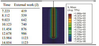
Meanwhile, according to Eq. (9), the initial penetration velocity of the sampler is 1.26 m s−1, and the penetration depth is 500 mm. When the sediment and loss of power due to friction with the sampling tube wall are ignored, the kinetic energy is Ek = 1/2 mv2 = (1/2)×220×1.26×1.26 = 174.63 J. It is assumed that penetration depth l is the length of sediment in the penetration tube, the gravitational potential energy is Ep = mgl = 220×9.8×0.5 = 1078 J; and the sampler penetration energy is Et = Ek + Ep = 174.63 + 1078 = 1252.63 J. Thus, the sampler can provide injection energy, and the finite element analysis of the sampler needs external work to increase. Therefore, the theoretical calculation is more reasonable.
3.4 Sampling Tube Optimization and Sampler Pressure Bar StabilityAccording to the equation for calculating the sampling depth, the penetration depth of the sampler depends on its mass, the acceleration due to gravity, sediment limit stress, friction coefficient, and the maximum diameter. Considering the miniaturized design, four sampling pipe ring design, flexible cloth and recyclable design goals, sampling weight limit of 180 kg (150 kg target weight), and sampling depth limit of 500 mm, the sampling depth is only limited by the sampling pipe diameter and friction coefficient, which depends on τ. Therefore, the following actions were taken:
1) A water-lubricated composite material was used to reduce the friction between the sampling tube outer wall and the sediment. The outer wall was coated with a selflubricating ethylene material so that the limit of the friction coefficient was reduced to τ ≤ 0.01 kg cm−2.
2) Sampling tubes with diameters of 30, 40, 50, and 60 mm were designed for the sampling pipe sections, and the sampling depths were calculated. According to Eqs. (9) and (10), the corresponding final velocities are 3.57, 3.09, 2.77, and 2.53 m s−1, respectively. The relationship between the sampling depth and sampling volume for tubes of different diameters is illustrated in Fig.7.

|
Fig. 7 Sampling depth and volume under different diameters. |
Based on this figure, the optimal sampling diameter was selected as the intersection point of the sampling depth and the sampling volume; hence, the inner diameter of the sampling tube inner diameter was set to 50 mm.
The penetration resistance Fs and the buckling critical pressure Fcr during penetration were compared. The safety coefficient of the sampling tube during penetration is
| $ n1=\frac{{F}_{cr}}{{F}_{s}}. $ | (12) |
The penetration resistance can be expressed as
| $ {F}_{s}=f+{F}_{u}=\tau cgl+{\tau }_{u}\times {A}_{D}.$ | (13) |
The inertia moment is Fu = τu×AD, where Fu is the end face resistance. According to Euler's formula and the critical pressure theory for hinged slender bars on both ends, the algorithm for checking the stability of the pressure bars is as follows:
| $ {\delta }_{cr}=\frac{{F}_{cr}}{A}=\frac{{\rm{π}}^{2}EI}{{(\mu h)}^{2}A}. $ | (14) |
The inertia moment is I = i2A where i is the inertial radius of the cross section; thus,
| $ {\delta }_{cr}=\frac{{\rm{π}}^{2}E}{{(\frac{\mu h}{i})}^{2}}.$ | (15) |
The flexibility value λ (with dimension 1) is introduced as
| $ \lambda =\frac{\mu h}{i}. $ | (16) |
Substituting Eq. (16) into Eq. (15) gives the equation for calculating the critical stress:
| $ {\delta }_{cr}=\frac{{\rm{π}}^{2}E}{{(\lambda)}^{2}}. $ | (17) |
The flexibility value has significant parametric effects on the critical stress and reflects factors such as length, cross section, constraint conditions, and shape.
The sampling tube is made from 304 stainless steel with an elasticity modulus E of 210 GPa and proportional limit of δp = 280 MPa.
Furthermore, the effect of the sampling tube diameter on the tube stability was investigated. The critical buckling pressure Fcr and penetration length of 1.5 m-long sampling tubes with different pipe diameters were studied (Fig.8), along with the changes in the penetration resistance Fs and penetration length (Fig.9).

|
Fig. 8 Curve of instability critical pressure change with penetrative length. |

|
Fig. 9 Curve of penetration resistance change with penetrative length. |
Based on the calculations, the critical buckling load is greater than the penetration resistance, and the safety coefficient is greater than 1.2. Thus, the sampling tube meets the stability requirements of the pressure bars.
4 Experimental Verification 4.1 Experimental and Theoretical DataBased on the sampler design, a prototype was manufactured with a mechanical release mechanism as shown in Fig.10.

|
Fig. 10 The prototype of full-depth self-floating sampler. |
The prototype included a buoyancy material, support for the middle framework, a grounding release mechanism, a sampler orientation mechanism, four sampling tubes, pawl springs, and a 150 kg balance-weight-block. The total mass of the prototype device was 180 kg, and the diameter of each sampling tube was 50 mm.
The prototype was tested in the gulf of the National Deep Sea Base shown in Fig.11. Considering the geological environment, an area of sandy clay was selected as the sampling object. The sampler was launched from the back of the ship's deck (approximately 5 m high above the ship and 6 m deep in water). After recovery, the sampling tube was removed, and the sampling length was measured. These steps are demonstrated in Fig.10, and the experimental data are presented in Table 1.

|
Fig. 11 Offshore test. a, launch on the ship; b, recovery; c, measure and analysis of the sample. |
Previous marine geological research has shown that the geomechanical parameters of deep-sea sediments vary with sampling depth and location. The ultimate frictional coefficient varies substantially across different locations and sediment types. The parameters are summarized in Table 2.
|
|
Table 2 Geomechanical parameters of abyssal sediments |
Based on historical geological data obtained from the Jiaolong voyage, the seabed conditions in the flat area of the Mariana Trench in the western Pacific Ocean were used as a reference, and sandy ooze clay was selected for the calculation parameters in this study. According to Eq. (10) and the parameters of the sampler used in this experiment, the sampler penetration depths are presented in Table 3.
|
|
Table 3 Summary table of theoretical calculation and actual penetration depth of sampler |
By comparing the theoretical and experimental data, we conclude that the equations agree well with the actual results. In addition, analysis of the test results suggests that a functional relationship exists between the ultimate frictional coefficient of the sediment and the sampler penetration depth. To maximize the penetration depth, the dead weight should be increased and the coefficient of friction between the sampling tube and the sediment should be minimized.
Based on calculations using Eq. (10), the penetration depth is closely related to the mass and density of the sampler, the circumference and maximum diameter of the penetrating tube, the ultimate stress frictional coefficient, and the seawater density. Therefore, Eq. (10) may be used as a reference to provide a theoretical basis for sampler design.
5 ConclusionsIn this study, we designed a new self-floating seabed sampler that incorporates elements from traditional gravity-driven samplers. We analyzed the properties that affect the penetration depth and developed an equation that can be used for optimization. This equation was applied to the new sampler design, and the results were compared with the experimental results obtained using a prototype sampler and historical data. The comparison revealed that the theoretical results agree well with the experimental results. Therefore, this work can be used as a reference in future sampler designs.
However, there were some limitations that we hope to address in future works:
1) Since the Jiaolong manned submersible is currently undergoing technical upgrades we could only conduct experiments in the harbor. Therefore, we plan to carry out sea trials next year during the next voyage.
2) At present, the full-ocean-depth self-floating sampler can be used only on flat areas of the abyss. Hence, we plan to develop a self-adjusting sampler that can operate on sloped areas.
3) In the experiments, we observed that the factors affecting the penetration depth varied with the location, depth, and substrate with a nonlinear relationship. We plan to conduct further research in the future to optimize these nonlinear parameters using the fuzzy control theory.
Nomenclature|
|
This research was jointly supported by the Stable Supporting Fund of Science and Technology on Underwater Vehicle Technology (No. JCKYS2019604SXJQR-06), the National Natural Science Foundation of China-Marine Science Research Center of Shandong Provincial Government Joint Funding Project (No. U1606401), the National Natural Science Foundation of China (No. 61603108), the Taishan Scholar Project Funding (No. tspd20161007), the National Key Research and Development Plan (Nos. 20 16YFC0300704, 2017YFC030660). We would like to give special thanks to the crew on Leg II of the 37th China Dayang Cruise along the southwestern area of the Mariana Trench. The diving area on this leg is on the southern slope of the Challenger Deep between 6300 and 8300 m deep. Valuable sediment data and samples were obtained during this voyage and the data provided were crucial to this work.
Blankenship-Williams, L. E. and Levin, L. A., 2009. Living deep: A synopsis of hadal trench ecology. Marine Technology Society Journal, 43(5): 137-143. DOI:10.4031/mtsj.43.5.23 (  0) 0) |
Bowen, A. D., Yoerger, D. R., and Taylor, C., 2008. The Nereus hybrid underwater robotic vehicle for global ocean science operations to 11000 m depth. Oceans IEEE. Hawaii, 867-873.
( 0) |
Bu, J. W., Yan, T. N. and Bu, S. R., 2000. Structure and working principle of controllable sampler. Geological Science and Technology Information, 19(4): 100-104 (in Chinese with English abstract). ( 0) |
Bu, J. W., Yan, T. N. and Cheng, H. Z., 2001. Structure and working principle of floating-balls sampler. Geological Science and Technology Information, 20(1): 109-112 (in Chinese with English abstract). ( 0) |
Clemens, S. C. and Tiedemann, R., 1997. Eccentricity forcing of Pliocene – early Pleistocene climate revealed in a marine oxygen-isotope record. Nature, 385(6619): 801-804. DOI:10.1038/385801a0 ( 0) |
Cui, W. C., Hu, Y. and Guo, W., 2017. Chinese journey to the Challenger Deep: The development and first phase of sea trial of an 11000-m Rainbowfish ARV. Marine Technology Society Journal, 51(3): 23-35. DOI:10.4031/MTSJ.51.3.2 ( 0) |
Gao, X., Ding, K. and Ren, Y. G., 2017. Target deployment and retrieval using Jiaolong manned submersible in the depth of 6600 m in Mariana Trench. China Ocean Engineering, 31: 618-623. DOI:10.1007/s13344-017-0071-9 ( 0) |
Hoyaux, B. and Ladanyi, B., 1970. Gravitational stress field around a tunnel in soft ground. Canadian Geotechnical Journal, 7(1): 54-61. DOI:10.1139/t70-005 ( 0) |
Jamieson, A. J., Fujii, T., Solan, M. and Priede, I. G., 2009. HADEEP: Free-falling landers to the deepest places on earth. Marine Technology Society Journal, 43(5): 151-160. DOI:10.4031/mtsj.43.5.17 ( 0) |
Liu, F., 2014. Jiaolong manned submersible: A decade's retrospect from 2002 to 2012. Marine Technology Society Journal, 48(3): 7-16. DOI:10.4031/mtsj.48.3.14 ( 0) |
Mingram, J., Negendank, J. F. W., Brauer, A., Berger, D., Hendrich, A., Köhler, M. and Usinger, H., 2007. Long cores from small lakes – Recovering up to 100 m-long lake sediment sequences with a high-precision rod-operated piston corer (Usinger-corer). Journal of Paleolimnology, 37(4): 517-528. DOI:10.1007/s10933-006-9035-4 ( 0) |
Nunoura, T., Nishizawa, M. and Hirai, M., 2018. Microbial diversity in sediments from the bottom of the Challenger Deep, the Mariana Trench. Microbes and Environments, 33(2): 186-194. ( 0) |
Qin, H. W., Chen, J. Q., Wang, J. J. and Chen, Y., 2013. Design and sea trial research of new hydrostatic corer. China Mechanical Engineering, 24(7): 942-945 (in Chinese with English abstract). ( 0) |
Wolff, T., 1970. The concept of the hadal or ultra-abyssal fauna. Deep Sea Research, 17: 983-1003. DOI:10.1016/0011-7471(70)90049-5 ( 0) |
Yoshida, H., Ishibashi, S. and Watanabe, Y., 2009. The ABISMO mud and water sampling ROV for surveys at 11000 m depth. Marine Technology Society Journal, 43(5): 87-96. DOI:10.4031/MTSJ.43.5.31 ( 0) |
Zachos, J., Pagani, M. and Sloan, L., 2001. Trends, rhythms, aberrations in global climate 65 Ma to present. Science, 292(5517): 686-693. DOI:10.1126/science.1059412 ( 0) |
Zhang, Q. L., Liu, G. J. and Guo, Y. L., 2009. The structural design and dynamic analysis of collecting process of new type seabed sampler. Ocean Technology, 28(4): 20-23 (in Chinese with English abstract). ( 0) |