2) Key Laboratory of Environment Controlled Aquaculture, Ministry of Education, Dalian 116023, China;
3) State Key Laboratory of Coastal and Offshore Engineering, Dalian University of Technology, Dalian 116024, China
In recent years, the destruction of marine environment has aggravated, and the development of deep-sea aquaculture is becoming an inevitable trend. The safety of fishing cages has become a primary problem for the deep-sea aquaculture. As an important part of the net cage system, the net will undergo large deformation when exposed to complex wave and current when using traditional flexible fiber, which will seriously impact the fish living space and result in the reduction of sea products.
With the advantages such as high resistances to wave and current, anti-fouling, corrosion-resistant and antibacterial properties, and environmentally friendly properties, metal cage is regarded as a new potential facility for deep-sea aquaculture. Different from traditional woven net, the metal net is fabricated by three-dimensional metal wires. Given this particularity of the metal structure, the mechanical performance and hydrodynamic characteristics of metal net under wave-current dramatically differs with normal ocean structure. Therefore, the investigation on the mechanical properties and hydrodynamic characteristics of the metal net features has practical significance to the development of structural safety design and promotion of the domestic deep-sea metal cage application in the sustainable marine aquaculture industry.
The main approaches for investigating the hydrodynamic behavior of fish cages include numerical simulation and physical tests. For example, Fredriksson et al. (2003) simulated the dynamics of a fish cage and mooring system with physical and numerical models, and the results were compared with field observations. Lader and Enerhaug (2005) introduced a scale model of flexible circular net test, and the drag and lift forces on net structures from the test were compared with the calculated results from empirical-based formulas. Li et al. (2005) proposed a rigidity modification formula for the simulation criteria of fishing nets by using Froude's law and ensured the use of smaller model scale (1:20) for deep-water cage experiments. In recent years, different numerical models have been constructed to simulate different parts of fish cages in waves, and these finite element method (FEM)-based simulation models were used to analyze and optimize net cages. Lee et al. (2015) used a mass-spring model to analyze the dynamic behavior and the corresponding deformation of fish cage systems. Huang et al. (2016) constructed a FEM-based numerical model to simulate a floating fish cage collar and mooring system, and the numerical model was applied to a dynamic simulation of the elastic deformation of the system. Liu et al. (2017) established finite element-based solid models for deep-water net cage guardrails and investigated the mechanical properties of hexagon – triangle and circle-type guardrails.
At present, physical experiments and numerical simulations are the main tools for determining the mechanical properties of nets. For numerical simulation, scholars worldwide have achieved considerable research progress in the hydrodynamic characteristics of fiber nets in the past years. Gosz et al. (1996) used a bar element to simulate the submerged offshore net cage system and used the Gauss-Seidel iterative method to solve the motion response of the cage system and its associated moorings. Bessonneau and Marichal (1998) used rigid bars to simulate the flexible net structure and analyzed the hydrodynamic characteristics of the trawl by using the finite difference scheme to solve the discretized dynamic equations. Fredheim and Faltinsen (2001) used spherical and cylindrical elements to simulate the net-connecting nodes and net lines, respectively, and established a coupled model of current and net; then, the current resistance of the netting was evaluated by the model. Lader et al. (2001) discretized the net into super elements and assumed that the velocity force acting on the unit structure plays a major role; then, they developed a calculation model for the circular three-dimensional (3D) net system under the conditions of wave and flow. Marichal (2003) investigated the deformation characteristics of the net under the trawl of current by finite difference method-based numerical methods. Tsukrov et al. (2003) constructed an equivalent net element to model the hydrodynamic response of the net panels exposed to environmental loadings, which include drag, buoyancy, and inertial and elastic forces exerted on the netting by current and force, and used the Newmark method to solve the vibration equation of the net. Suzuki et al. (2003) and Lee et al. (2005) used a mass-spring element to simulate the hydrodynamic characteristics of fishing nets. Li et al. (2006) and Zhao et al. (2007) derived a mass-spring model for planar and 3D nettings made of polyethylene, respectively, and the estimated net configurations and loadings qualitatively agreed with the model tests. Su and Zhan (2007) used the FEM to simulate the spatial deformation of a flexible mesh and the mesh-grouping method to reduce the number of freedoms. Li et al.(2012, 2013a, 2013b) used the truss element to simulate the net and investigated the net deformation under wave-current and irregular waves. All the above simulation models were constructed for flexible fiber nets and compared with fiber-class nets, but the investigation on the numerical simulation of the mechanical characteristics of metal nets is relatively limited.
The metallic rhombic chained net (MRCN), which is a porous elastic structure fabricated by small-diameter metal lines, possess specific properties, such as high global bending stiffness and small local deformation. These specific mechanical properties have resulted in investigations on the metal chain-link net. Swift et al. (2011) proposed empirical values for normal drag coefficients based on experimental studies of drag forces on copper alloy net panels. Decew et al. (2013) investigated the influence of bending stiffness of copper alloy on net deformation through physical tests and numerical simulation. Drach et al. (2016) used a solid finite element to simulate the stress distribution of the connecting part within the copper alloy rhombic chain net subjected to static loading, whereas Nie et al. (2016) summarized the latest applications, research, and development about several types of copper alloy netting. Chen et al. (2017) established a fluid-solid coupled model to simulate the interactions between a fluid and 2D metal net based on the principle of computational fluid dynamics and analyzed the relationship between the current force, the diameter of weave net lines, and net configurations of the zinc aluminum alloy net. Cha and Lee (2018) established load on a circular fish cage with chain-linked copper alloy net under the action of ocean currents and waves.
In this paper, a finite element model is built for a 3D MRCN structure, and beam and connector elements are used to simulate the 3D net structure and the joint place. The static and hydrodynamic responses of the netting structure can be obtained by solving the corresponding finite element functions, and the external force is simulated when the netting structure is under the action of static concentrated force and current with consistent velocity. The NDI Optotrak 3D optical measurement system is used to measure the displacement of the net subjected to static concentrated force, whereas towing tests with different current velocities are carried out to measure the drag force of the net subject to uniform current. By comparing the simulated values the with the test results, the finite element static model is verified to be effective and correct, thus validating the rationality and accuracy of the hydrodynamic response analysis model of metal nets. With the established finite element model, the hydrodynamic responses of the netting structures under different working conditions are obtained. The numerical simulation method proposed in this paper will provide a useful guidance for the investigations of the hydrodynamic characteristics of metal cages in deep-sea aquaculture and the safety design of the net cage structure.
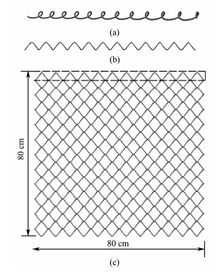
2 Static Analysis Model of Metal Net 2.1 Net Cage Model DescriptionsThe MRCN is a 3D multi-porous structure with small radius. With such structural characteristic, the single metal spiral wire is modeled first, and the wire-based array is then combined to form the netting structure (Fig.1). The model consists of zinc aluminum alloy with the detailed parameters listed in Table 1. The mesh size is 45.0 mm with a wire diameter of 4.0 mm.
|
Fig. 1 (a) Single wire in MRCN. (b) Side view of single wire in MRCN. (c) Front view of MRCN. |
|
|
Table 1 Properties of MRCN |
First, as the main loading on metal chain net is a bending load, which is caused by out-of-plane current or waves in exposed marine environment, the main deformation of the spiral metal chains is a relatively small displacement and large rotation around the connecting places of adjacent chains. Thus, beam elements should be used to simulate the metal spiral chains based on the basic deformation and mechanical properties of MRCN. The numerical model proposed in this paper can be used to simulate the metal chain net structure with the assumption that the metal chains are linear elastic. Second, as the compression around the connecting places of adjacent spiral chains is extremely complex with boundary conditions, environmental currents, and waves, the compression around the connecting places will change with pretension, space, and time. Thus, the computational cost will increase given the numerous connecting places in a plane MRCN structure. Therefore, a simplified mechanical model for the connecting places of adjacent chains in MRCN needs to be built for the simulation, analysis, and design of the net cage exposed to actual environments. In this paper, hinge joints are introduced to simulate the connecting places of adjacent spiral chains based on the woven pattern and mechanical properties of constraint and deformation mode of the MRCN. This mechanical model is appropriate when the connecting places connect with each other, and the compression is less than the critical compression. The proposed simplified mechanical model will substantially reduce the computational cost and agree with the basic deformation of metal chain nets exposed to current and waves. The beam element is used as the net wire in the 3D MRCN structure (Fig.2). Considering the relatively small displacement and large rotation at the joint point, the connector element is introduced to model the contact effects between wires. Then, the model with a total size of 80 × 80 cm2 is established, incorporating 6358 nodes in 6336 beam elements and 263 connector elements.

|
Fig. 2 Mesh of the net structure. |
The beam element of the netting includes three degrees of freedom, and the corresponding discrete equilibrium function is as follows:
| $\mathit{\boldsymbol{Kx}}{\rm{ = }}\mathit{\boldsymbol{Q}}, $ | (1) |
where K and Q are the beam element stiffness and node force vector, respectively, and x is the node displacement. The stiff matrix K and load vector Q can be expressed as follows:
| $\left\{ {\begin{array}{*{20}{c}} {\mathit{\boldsymbol{K}} = \sum\limits_e {{\mathit{\boldsymbol{K}}^e}, {\mathit{\boldsymbol{K}}^e} = \int\limits_{{V_e}} {{\mathit{\boldsymbol{B}}^{\rm{T}}}\mathit{\boldsymbol{DB}}{\rm{d}}V} } \;\;\;\;\;\;\;\;\;\;\;\;}\\ {\mathit{\boldsymbol{Q}} = \sum\limits_e {{\mathit{\boldsymbol{Q}}^e}}, {\mathit{\boldsymbol{Q}}^e} = \int\limits_{{V_e}} {{\mathit{\boldsymbol{N}}^{\rm{T}}}\mathit{\boldsymbol{f}}{\rm{d}}V} + \int\limits_{S_\sigma ^e} {{\mathit{\boldsymbol{N}}^{\rm{T}}}\mathit{\boldsymbol{T}}{\rm{d}}s} } \end{array}} \right., $ | (2) |
where Ke and Qe are element stiffness and element load vector, respectively, N is the interpolation function matrix, D is the elastic matrix, f is the node loading matrix composed of element volume force, T is the node loading matrix of element surface forces, Ve is the element volume, and
|
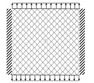
Fig. 3 Static loading test of MRCN. |
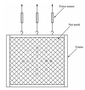
Static tests are carried out to measure the displacements of the joint point under the combined loads of single direction tension and concentrated force (Fig.4). The displacements of the left and right boundaries of the netting are fixed in the direction parallel to the applied force, and the bottom side is fixed to the angle steel frame of 40.0 mm × 40.0 mm × 4.0 mm. The concentrated force is measured by a force sensor, and the displacements are measured through a 3D multi-degree optical measuring system (NDI Optotrak) stored in the computer. Seventeen data acquisition points are symmetrically arranged on the surface of the netting, as shown in Fig.4.
|
Fig. 4 Layout of measuring points. |
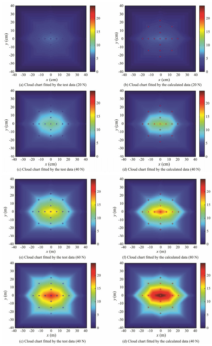
With the obtained displacements from the 17 measuring points, the cloud maps of the netting structures are obtained under concentrated forces of 20, 40, 60, and 80 N and compared with the simulated results shown in Fig.5, in which (a), (c), (e), and (g) are obtained by the tests, and (b), (d), (f), and (h) originate from the numerical simulation. The same conclusion can be obtained, that is, both the largest displacement and deformation range increase with the loading amplitude.
|
Fig. 5 (a)–(d) Comparison of the displacement cloud chart fitted by the test and calculated data. |
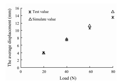
The relative errors for the concentrated loads of 20, 40, 60, and 80 N are 2.13%, 4.19%, 6.64%, and 11.35%, respectively, and the overall average error is 6.08%. Furthermore, the relative error of the calculated value decreases when the value of concentrated force is smaller, and the relative errors will increase with the concentrated force. Fig.6 shows the average relative errors between the calculated and test values for the four conditions.
|
Fig. 6 Comparison of the average values of the test and simulated displacements under four loading conditions. |
The simulation and tests show that introduction of the connector elements effectively simulates the interactions among different wires in the pretensioned netting structure with the advantages of reducing computation and improving the accuracy.
3 Hydrodynamic Model of the Metal Netting 3.1 Dynamic Equation of the Netting StructureWith the initial conditions of
| $\mathit{\boldsymbol{M\ddot x}}\left(t \right) + \mathit{\boldsymbol{Kx}}\left(t \right) = \mathit{\boldsymbol{Q}}, $ | (3) |
where M, K, and Q are the structure mass matrix, structure stiffness matrix, and structure load vector, respectively.
| $\left\{ {\begin{array}{*{20}{c}} {\mathit{\boldsymbol{M}} = \sum\limits_e {{\mathit{\boldsymbol{M}}^e}}, {\mathit{\boldsymbol{M}}^e} = \int\limits_{{V_e}} {\rho {\mathit{\boldsymbol{N}}^{\rm{T}}}\mathit{\boldsymbol{N}}{\rm{d}}V} \;\;\;\;\;\;\;\;\;}\\ {\mathit{\boldsymbol{K}} = \sum\limits_e {{\mathit{\boldsymbol{K}}^e}}, {\mathit{\boldsymbol{K}}^e} = \int\limits_{{V_e}} {{\mathit{\boldsymbol{B}}^{\rm{T}}}\mathit{\boldsymbol{DB}}{\rm{d}}V} \;\;\;\;\;\;\;\;\;\;\;\;}\\ {\mathit{\boldsymbol{Q}} = \sum\limits_e {{\mathit{\boldsymbol{Q}}^e}}, {\mathit{\boldsymbol{Q}}^e} = \int\limits_{{V_e}} {{\mathit{\boldsymbol{N}}^{\rm{T}}}\mathit{\boldsymbol{f}}{\rm{d}}V} + \int\limits_{S_\sigma ^e} {{\mathit{\boldsymbol{N}}^{\rm{T}}}\mathit{\boldsymbol{T}}{\rm{d}}s} } \end{array}} \right., $ | (4) |
where Me, Ke, and Qe denote the element mass matrix, element stiffness matrix, and element load vector, respectively. N is the interpolation function, B is the strain matrix, Ve is the volume element,
In the towing tests, the netting structure suffers from gravity, buoyant force, and current force. By using the beam element to discretize the whole structure, the total force applied to the unit length beam with circular crosssection, including the gravity and buoyant forces, can be determined:
| ${P_z} = {\rho _m}gV - {\rho _w}gV = ({\rho _m} - {\rho _w})g\frac{{{\rm{ \mathit{ π} }}{D^2}}}{4}, $ | (5) |
where PZ is the total force applied to the unit length beam, ρm is metal density, ρw is water density, D is the beam diameter, and V is the volume of the unit length beam.
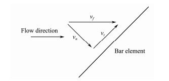
The current force applied on the netting composed of small radius substructures can be calculated by the Morison equation. The current velocity can be divided into normal and tangential components, such that the current force depicted in Fig.7 can be expressed as follows:
|
Fig. 7 Tangent and normal components of fluid velocity relative to the structure. |
| ${F_n} = \frac{1}{2}{\rho _w}{C_n}D\Delta {v_n}\left| {\Delta {v_n}} \right|, $ | (6) |
| ${F_t} = \frac{1}{2}{\rho _w}{C_t}{\rm{ \mathit{ π} }}D\Delta {v_t}\left| {\Delta {v_t}} \right|, $ | (7) |
where Fn is the normal force of the unit length beam, Cn is the normal drag coefficient, vn is the relative velocity in the normal plane, Ft is the tangential force of the unit beam, Ct is the tangential drag coefficient, and vt is the relative velocity in the beam's tangential plane.
Both the normal and tangential drag coefficients can be calculated by the method proposed by Choc and Casarella (1971), they updated the drag coefficients based on the Reynolds number as follows:
| ${C_n} = \left\{ {\begin{array}{*{20}{l}} {8{\rm{ \mathsf{ π} }}\left( {1 - 0.87{s^{ - 2}}} \right)/{{{\mathop{\rm Re}\nolimits} }_n}s,\left( {0 < {{{\mathop{\rm Re}\nolimits} }_n} \le 1} \right)}\\ {1.45 + 8.5{\mathop{\rm Re}\nolimits} _n^{ - 0.90},\left( {1 < {{{\mathop{\rm Re}\nolimits} }_n} \le 30} \right)}\\ {1.1 + 4{\mathop{\rm Re}\nolimits} _n^{ - 1/2},\left( {30 < {{{\mathop{\rm Re}\nolimits} }_n} \le {{10}^5}} \right)} \end{array}} \right.,$ | (8) |
| ${C_t} = {\rm{ \mathit{ π} }}\mu (0.55{\rm{Re}}_n^{1/2} + 0.084{\rm{Re}}_n^{2/3}), $ | (9) |
| ${\rm{R}}{{\rm{e}}_n} = \frac{{\rho {V_{Rn}}D}}{\mu }, $ |
| $s = - 0.07721565 + \ln \left({8/{\rm{R}}{{\rm{e}}_n}} \right), $ |
where VRn is the particle relative speed, ρ is water density, and μ is the water viscosity coefficient.
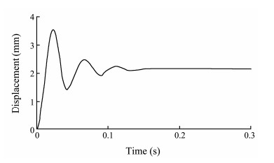
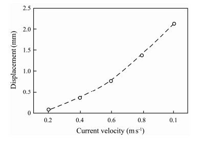
3.3 Transient Deformation of the Netting StructureThe discretized equation of motion is solved by software ABAQUS. The intersection points among the net wires are simulated by the connector elements, and the two joining points accurately refer to the two nodes of the beam element. The net cell comprises 4.0 mm metal wires with a mesh size of 45 mm. When the current velocity is 1.0 m s−1, the center-node displacement of the net clothing structure is computed (Fig.8). In the initial state, a fluctuation exists in the response curve. After 0.16 s, the response stabilizes, and the maximum displacement is constantly located at the center node of the netting structure. The maximum displacement of the netting structure subjected to uniform current increases exponentially with the current velocity (Fig.9), and the detailed deformation modes of the netting structure under different current velocities are shown in Fig.10.
|
Fig. 8 Displacement of the central node of the net varies with time. |
|
Fig. 9 Displacements of the central node in the net varies with current velocity. |

|
Fig. 10 Net displacements under five currents (amplification factor is 100). |
The 3D MRCN used in the hydrodynamics tests is manufactured with the same plane size with that in static tests. Wires with diameters of 2.5, 3.2, and 4.0 mm are utilized to fabricate the netting structure with mesh sizes of 25.0, 35.0, and 45.0 mm, respectively. The material properties are listed in Table 1. The physical model tests are conducted in the Ship Model Tank of Dalian University of Technology, which is a member of the International Towing Tank Conference, and the size of the tank is 170 m × 7 m × 4 m (length × width × depth). Fig.11 shows the arrangements of the test, in which the four sides of the netting are fixed on a steel frame, on the top of which are the tensor and data acquisition system. During the tests, all the net parts are submerged in water with a gap of 15 cm between the upper limb and the surface. The velocity towing carriage is controlled at 0.2, 0.4, 0.6, 0.8, and 1.0 m s−1 to simulate the corresponding current velocity. Then, the forces of the netting towed by trailing are collected by the data acquisition system equipment.
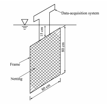
|
Fig. 11 Set-up of net sheet dragging test. |
In the tests, 45 cases of force conditions of the netting structure are obtained; the cases include nine kinds of netting structures under five different flow velocities. Fig.12 shows the comparisons between the simulation and tests for the netting structures with different diameters and cell sizes.

|
Fig. 12 Comparison of simulation and test results of net force. |
Both the results from numerical simulation and tests show that the drag forces on the nets vary with current velocities and mesh sizes. First, the drag forces vary exponentially with the current velocity. The simulation and tests show good agreement, whereas the maximum error is 10.2% when the current velocity is 0.2 m s−1. The minimum error is 6.32% when current velocity is 0.6 m s−1, and the average error is 8.13%. Second, the drag forces reduce with the mesh sizes of the net, and comparing with the drag forces from the tests, the average errors of the proposed numerical simulation are 4.1%, 1.7%, and 8.9% for the nets with cell sizes of 25, 35, and 45 mm, respectively. Table 2 provides the average errors of drag forces for different velocities. According to the test results, the validity of the proposed numerical simulation method is verified, and the numerical simulation method is limited to the simulation of the force and deformation of chain metal netting in uniform current. The errors between the numerical simulation and tests originate from the stress and friction around the connecting points; this stress results from the pretension from the boundary condition. In conclusion, the proposed simulation method is robust with the assumption that the metal chains are linear elastic, and the compressions at the connecting places of adjacent chains are under critical stress. The proposed simplified mechanical model can reveal the basic deformation of the MRCN exposed to current and waves, whereas the proposed simulation method will provide a useful guidance for the investigations of the hydrodynamic characteristics of metal cages in deep-sea aquaculture and the safety design of net cage structures. Potential issues, such as simulation and testing methods on the in-plane Poisson ratio of the metal chain net, bending stiffness with a certain in-plane pretension of the metal chain net structure, and a simplified numerical mechanical model including the affections of in-plane pretension for metal chain nets under exposed marine environment, will be addressed in future works.
|
|
Table 2 Relative average error of drag force (%) |
Considering the small diameter of the 3D MRCN structure, the finite element model of the MRCN structure is established. Through static loading and towing tests, the effectiveness of the MRCN model is validated through the measured displacements and hydrodynamic drag forces. Hence, a hydrodynamic model is established for the MRCN structure subjected to uniform current. Through numerical and test analyses, the related conclusions are obtained:
1) With the good consistency between the simulation and tests, the proposed MRCN model with beam elements and connector elements can accurately predict its response in a certain deformation range and significantly reduce the computational cost.
2) The hydrodynamic drag forces can be precisely simulated by using the proposed method, with an average error of 8.13% compared with that of the towing tests in five different uniform currents.
3) With the hydrodynamic model, the dynamic deformation process of the MRCN structure is obtained by using the transient analyzing method, which can effectively solve the difficult computation problem arising from the small-diameter metal net structure.
AcknowledgementThis work is financially supported by the National Natural Science Foundation (No. 31572663).
Bessonneau, J. S. and Marichal, D., 1998. Study of the dynamics of submerged supple nets (applications to trawls). Ocean Engineering, 25(7): 563-583. DOI:10.1016/S0029-8018(97)00035-8 (  0) 0) |
Cha, B. J. and Lee, G. H., 2018. Performance of a model fish cage with copper-alloy net in a circulating water channel and wave tank. Ocean Engineering, 151: 290-297. DOI:10.1016/j.oceaneng.2018.01.053 (  0) 0) |
Chen, C. P., Wang, W., Zheng, J. C., Shi, X. Y. and Liu, C. F., 2017. Numerical simulation on the hydrodynamic characteristic of the plane metal net under current. Journal of Dalian Ocean University, 32(3): 363-368 (in Chinese with English abstract). (  0) 0) |
Choc, Y. I. and Casarella, M. J., 1971. Hydrodynamic resistance of towed cables. Journal of Hydronautics, 5(4): 126-131. DOI:10.2514/3.62882 (  0) 0) |
Decew, J., Osienski, M., Drach, A., Celikkol, B., and Tsukrov, I., 2013. Effect of the bending stiffness on the volumetric stability of fish cages with copper alloy netting. International Conference on Computational Methods in Marine Engineering. Hamburg, Germany, 1-7.
(  0) 0) |
Drach, A., Tsukrov, I., Decew, J. and Celikkol, B., 2016. Engineering procedures for design and analysis of submersible fish cages with copper netting for exposed marine environment. Aquacultural Engineering, 70: 1-14. DOI:10.1016/j.aquaeng.2015.11.001 (  0) 0) |
Fredheim, A., and Faltinsen, O. M., 2001. A numerical model for the fluid structure interaction of three-dimensional net structure. Proceeding of the 5th International Workshop 'DEMaT 01'. University of Rostock, Germany, 2.
(  0) 0) |
Fredriksson, D. W., Swift, M. R., Irish, J. D., Tsukrov, I. and Celikkol, B., 2003. Fish cage and mooring system dynamics using physical and numerical models with field measurements. Aquacultural Engineering, 27: 117-146. DOI:10.1016/s0144-8609(02)00043-2 (  0) 0) |
Gosz, M., Kestler, K. J., and Swift, M. R., 1996. Finite element modeling of submerged aquaculture net pen system. In: Open Ocean Aquaculture. Maine Sea Grant College Program Rpt. New Hampshire, 523-554.
(  0) 0) |
Huang, X. H., Guo, G. X., Tao, Q. Y., Hu, Y., Liu, H. Y. and Wang, S. M., 2016. Numerical simulation of deformations and forces of a floating fish cage collar in waves. Aquacultural Engineering, 74: 111-119. DOI:10.1016/j.aquaeng.2016.07.003 (  0) 0) |
Lader, P. F. and Enerhaug, B., 2005. Experimental investigation of forces and geometry of a net cage in uniform flow. IEEE Journal of Oceanic Engineering, 30(1): 79-84. DOI:10.1109/joe.2004.841390 (  0) 0) |
Lader, R. F., Fredheim, A., and Lien, E., 2001. Dynamic behavior of 3D nets exposed to waves and current. Proceedings of the 20th International Conference on Offshore Mechanics and Arctic Engineering. Rio de Janeiro, OMAE, 1125.
(  0) 0) |
Lee, C. W., Lee, J. H., Cha, B. J., Kim, H. Y. and Lee, J. H., 2005. Physical modeling for underwater flexible systems dynamic simulation. Ocean Engineering, 32(3): 331-347. DOI:10.1016/j.oceaneng.2004.08.007 (  0) 0) |
Lee, C. W., Lee, J. and Park, S., 2015. Dynamic behavior and deformation analysis of the fish cage system using massspring model. China Ocean Engineering, 29(3): 311-324. DOI:10.1007/s13344-015-0022-2 (  0) 0) |
Li, L., Fu, S., and Li, R., 2012. Dynamic responses of the floating cage system in current and waves. International Conference on Ocean, Offshore and Arctic Engineering. ASME, 239-248, DOI: 10.1115/OMAE2012-83284.
(  0) 0) |
Li, L., Fu, S. and Xu, Y., 2013. Nonlinear hydroelastic analysis of an aquaculture fish cage in irregular waves. Marine Structures, 34: 56-73. DOI:10.1016/j.marstruc.2013.08.002 (  0) 0) |
Li, L., Fu, S., Xu, Y., Wang, J. and Yang, J., 2013. Dynamic responses of floating fish cage in waves and current. Ocean Engineering, 72: 297-303. DOI:10.1016/j.oceaneng.2013.07.004 (  0) 0) |
Li, Y. C., Gui, F. K., Zhang, H. H. and Guan, C. S., 2005. Simulation criteria of fishing nets in aquiculture sea cage experiments. Journal of Fish Sciences of China, 12(2): 179-187 (in Chinese with English abstract). (  0) 0) |
Li, Y. C., Zhao, Y. P., Gui, F. K. and Teng, B., 2006. Numerical simulation of the hydrodynamic behavior of submerged plane nets in current. Ocean Engineering, 33(17-18): 2352-2368. DOI:10.1016/j.oceaneng.2005.11.013 (  0) 0) |
Liu, H., Wang, S., Huang, X., Tao, Q., Hu, Y., Guo, G. and Song, L., 2017. Mechanical property analysis and optimization of deep-water net cage guardrail. Transactions of the Chinese Society of Agricultural Engineering, 33(4): 248-257 (in Chinese with English abstract). DOI:10.11975/j.issn.1002-6819.2017.04.034 (  0) 0) |
Marichal, D., 2003. Cod-end numerical study. Proceedings of Hydroelasticity in Marine Technology. Oxford, 11-18.
(  0) 0) |
Nie, Z. W., Wang, L., Liu, Y. L., Shi, J. G., Min, M. H., Yu, W. W., Chen, X. W. and Wang, L. M., 2016. Development and application of fishery copper alloy netting. Marine Fisheries, 38(3): 329-336 (in Chinese with English abstract). (  0) 0) |
Su, W. and Zhan, J. M., 2007. Computational method for deformation of volume of net structure in current. The Ocean Engineering, 25(1): 93-100 (in Chinese with English abstract). (  0) 0) |
Suzuki, K., Takagi, T., Shimizu, T., Hiraishi, T., Yamamoto, K. and Nashimoto, K., 2003. Validity and visualization of a numerical model used to determine dynamic configurations of fishing nets. Fisheries Science, 69(4): 695-705. DOI:10.1046/j.1444-2906.2003.00676.x (  0) 0) |
Swift, M. R., Drach, A., Celikkol, B., Tsukrov, I. and DeCew, J., 2011. Chracterization of geometry and normal drag coefficients of copper nets. Ocean Engineering, 38(17): 1979-1988. DOI:10.1016/j.oceaneng.2011.09.019 (  0) 0) |
Tsukrov, I., Eroshkin, O., Fredriksson, D., Swift, M. R. and Celikkol, B., 2003. Finite element modeling of net panels using a consistent net element. Ocean Engineering, 30(2): 251-270. DOI:10.1016/S0029-8018(02)00021-5 (  0) 0) |
Zhao, Y. P., Li, Y. C., Dong, G. H., Gui, F. K. and Teng, B., 2007. Numerical simulation of the effects of structures ratio and mesh style on the 3D net deformation of gravity cage in current. Aquacultural Engineering, 36(3): 285-301. DOI:10.1016/j.aquaeng.2007.01.003 (  0) 0) |
 2019, Vol. 18


