2) State Key Laboratory of Hydraulic Engineering Simulation and Safety, School of Civil Engineering, Tianjin University, Tianjin 300072, China
With the growing demand for renewable energy, wind energy technologies have attracted extensive interest in the industry. The technology of offshore wind power systems has entered a rapid development stage in the past decades due to various advantages of offshore wind, including high wind speed and low turbulence (Dong et al., 2018). As the wind turbines move into deep water, the benefit of the floating offshore wind turbine (FOWT) is more prominent considering the economy, the convenience of installation, and total capacity compared with that of the fixed offshore wind turbine (Li et al., 2017a).
Wind turbines can be classified into horizontal axis wind turbines (HAWTs) and vertical axis wind turbines (VAWTs) considering different orientations of the rotational axis (Kumar et al., 2018). Various kinds of HAWTs have been widely adopted in the recent decades in offshore wind farm projects based on their highly developed design experiences despite their immaturity compared with their onshore counterpart (Hou et al., 2017; González et al., 2018). The size of the wind turbine is becoming increasingly large due to the massive power demands and the limitation of single-machine capacity. From this aspect, the enormous drivetrain placed on top of the HAWT will elevate the center of gravity, which may lead to a slightly robust system of the entire structure. HAWTs are also not considered to be an effective design for disorderly chaotic environments (Liu and Ho, 2016). Compared with the HAWTs, VAWTs capture the wind energy from any direction to cancel the yaw control system for the wind turbines (Wong et al., 2017; Kumar et al., 2018). Furthermore, the drivetrain system is designed at the lower position of VAWTs. Therefore, VAWTs have a considerable advantage in the large-scale development of offshore wind turbine (Liu et al., 2017b). The low conversion efficiency and difficulty in self-starting are the main shortcomings of VAWT designs (Eriksson et al., 2008; Tjiu et al., 2015). VAWTs could be a type of prospective wind gathering device applied in offshore environments considering their aforementioned superiority.
The floating foundations of offshore wind turbines mainly include Spar, TLP, and semi-submersibles based on the current customized technology from deepwater oil production platforms (Li et al., 2018a). The nonlinear dynamic responses of VAWTs are substantially more complex than the onshore ones considering the mobility of floating fluctuation. On the one hand, the issue of the floating system is multidisciplinary, including aerodynamics, hydrodynamics, mooring dynamics, and controlling theory (Coulling et al., 2013). On the other hand, the responses are highly coupled with the components, thus producing a sophisticated system (Borg and Collu, 2015). Establishing a coupled aero-hydro-mooring model is essential to investigate the dynamic responses of VAWTs comprehensively and examine the intricate dynamic characteristics between the environmental loads and wind turbine motions.
As one of the most significant differences between HAWTs and VAWTs, the aerodynamic performance is essential to the dynamic responses of the wind turbine. For HAWTs, a blade element momentum is a common approach to predicting the wind loads on the rotor. For the VAWTs, a series of aerodynamic calculating methods, including the double-multiple stream tube (DMST) model (Cheng et al., 2019), actuator cylinder model (Cheng et al., 2016), and other improved models based on these quasi-static approaches, could be adopted (Shires, 2013; Dyachuk and Goude, 2015; Wendler et al., 2016). Good agreements have been experimentally presented for the light rotors (Borg et al., 2014b); however, the inertia effects of rotating blades are not included on the basis of the quasi-steady assumption. Thus, other models, such as cascade, vortex, panel, and CFD models, were used to examine the aerodynamic performance (Mandal and Burton, 1994; Dixon et al., 2008; Murray and Barone, 2011; Goude and Bülow, 2013; Lei et al., 2017, 2019).
Another key issue of FOWT lies in the wave-body interactions on the floating structures. Collu et al. (2014) indicated that the wave loads were proven to provide a significant influence on the dynamic response of the VAWTs. In the research, barge- and semi-submersible-type buoys were conceptually designed to support the NOVA system. The semi-submersible design was optimized to balance the dynamic response and material cost. The CFD approaches were also widely investigated to calculate the hydrodynamic performance of FOWTs (Liu et al., 2017c; Salehyar et al., 2017; Bruinsma et al., 2018) despite their time-consuming characteristic.
The robustness of the entire system is guaranteed by the mooring system. The modeling of mooring lines and FOWT structural dynamics is highly related (Borg et al., 2014a). The force-displacement relationship (Liu et al., 2017a; Li et al., 2018b), catenary theory (Masciola et al., 2013; Li et al., 2017b; Liu et al., 2017b), and different kinds of multibody dynamic approaches (Hall et al., 2014; Hall and Goupee, 2015; Li et al., 2018c) were adopted to simulate the mooring loads according to the previous studies.
As mentioned above, the key issues considered in the dynamic analysis of floating VAWTs mainly include the following: the wave-body interaction effects on the floating structure, the unsteady aerodynamic effects, and the nonlinear restoring loads provided by the mooring system. An in-house coupled aero-hydro-mooring analysis model is established for a semi-submersible VAWT in the present work. A 3D potential theory module is applied in the model to evaluate the nonlinear hydrodynamic forces on the foundation. DMST theory is chosen to perform the aerodynamic calculations, while quasi-static catenary theory is used to simulate the mooring loads. The nonlinear dynamic responses of VAWTs under different scenarios could be simulated by coupling these algorithms in the time domain.
The paper is organized as follows. Primarily, the configuration and physical parameters of the VAWT are described in Section 2. The aero-hydro-mooring coupled model used in this research is then introduced in Section 3. A 2.6 MW floating VAWT model is adopted as an example to validate the code compared with experimental results in Section 4. The dynamic responses calculated on the basis of the code are analyzed under different scenarios in Section 5. Conclusions are finally drawn.
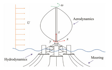
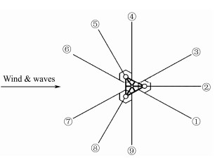
2 Physical Problem DescriptionAs shown in Fig. 1, the floating VAWT system studied in this work comprises a 2.6 MW Φ-type Darrieus wind turbine (Han, 2016) (Table 1) and a tri-floater semi-submersible floating foundation with nine mooring lines (Cao, 2012; Gao et al., 2013) (Table 2). Each mooring cable contains three parts, including an upper chain, middle wire, and lower chain, to reduce mass, and the details are presented in Table 3. The cables are divided into three groups distributed uniformly around the floating foundation (Fig. 2). All three cables in each group are connected to the fairleads on the corresponding buoy body of the tri-floater, and the angle between adjacent cables is 30˚. Among the cables, Line #2 is along the positive x-axis in the xz-plane. Herein, (x, y, z) is a Cartesian coordinate system originating at the mean free surface and the z-axis pointing upward. The direction of the incoming wind and wave is along Line #2, as shown in Fig. 2.
|
Fig. 1 Definition of the physical problem. |
|
|
Table 1 Parameters of the wind turbine |
|
|
Table 2 Parameters of the floating foundation and mooring system |
|
|
Table 3 Parameters of mooring cable |
|
Fig. 2 Mooring cables configuration. |
The numerical simulation performed in this work is partly based on the aero-hydro-mooring coupling code for HAWTs developed by Li et al.(2017b, 2018b). Hydrodynamic and mooring calculation methods are both used in this work. The wave-body interactions are calculated under the application of first- and second-order wave forces based on the potential flow theory and Morison's equation. A quasi-static catenary model (Li et al., 2018b) is used to calculate the tensions of the mooring system. The aerodynamic module is developed for VAWTs based on DMST theory. The algorithm will be clarified in the following section.
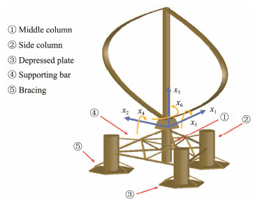
The floating VAWT system is regarded as a rigid body, and the dynamic response is calculated under the combined effects of wind, wave, and mooring lines. The dynamic equations of the floating VAWT can be presented as follows (Liu et al., 2017b):
| $\begin{aligned} & (\boldsymbol{M}+\boldsymbol{A}) \ddot{\boldsymbol{x}}(t)+\int_0^t \boldsymbol{h}(t-\tau) \dot{\boldsymbol{x}}(\tau) \mathrm{d} \tau+\boldsymbol{D} \boldsymbol{f}(\dot{\boldsymbol{x}})+\boldsymbol{K}(x) x \\ & =\boldsymbol{q}(t, x, \dot{x}), \end{aligned} $ | (1) |
where M is the mass and inertia matrixes of the floating VAWT, A is the added mass when the frequency approaches infinite, h(t) is the retardation function, and D is the viscous damping matrix. Potential flow theory assumes that the flow is ideal; thus, viscous damping is not included in this fluid simulation approach. Herein, relaxation tests are conducted to acquire the viscous damping coefficients. K is the restoring stiffness matrix provided by the semi-submersible buoy. q is the external force vector, which includes the Froud-Krylov and diffraction forces on the buoy, aerodynamic force on the rotor, wind pressure force on the tower, and the nonlinear restoring forces provided by the mooring cables.
|
Fig. 3 Six DOFs of the floating VAWT. |
DMST theory is chosen to predict the aerodynamic loads of the floating VAWT under turbine operation. The derivation process and validation of this model can be found in Liu et al. (2017b). Treating the floating VAWT as a rigid body, the variable interference factors, dynamic stall (Gormont-Berg model), tower shadow, Reynolds number variation (Paraschivoiu, 2002), and the influences of floating foundation motions on the induced velocities are considered. The wind pressure and wind heeling moment acting on the tower are also included in the simulation. These loads are calculated in accordance with the rules recommended by API (2005).
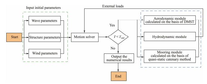
3.3 Simulation ProcessA coupled aero-hydro-mooring dynamic simulation tool for floating VAWT is developed in the time domain based on the modeling methods introduced in the above subsections, and the flowchart is shown in Fig. 4. The motion of the wind turbine at each time step is solved on the basis of Eq. (1) using fourth-order Runge-Kutta method. The position of the blade as well as the motion of fairleads is then derived using rigid body dynamics. Afterward, the aforementioned dynamic responses of the wind turbine are introduced into Eq. (1) to calculate the external loads in the next step. The coupling between the environmental loads and dynamic responses of the wind turbine system could be simulated using the aforementioned method.
|
Fig. 4 Flowchart of the coupled aero-hydro-mooring dynamic simulation tool. |
The numerical tool has already been validated by a spar-type FOWT (Li et al., 2018b, 2018c); however, further validation is still necessary to verify the accuracy of the simulation code developed in this work. On the one hand, the floating buoy used in this study is a semi-submersible foundation. The wave-body interaction is different from the spar one. On the other hand, the HAWT is adopted, and a specified aerodynamic module for VAWTs is developed in this work. Hence, model tests are conducted, and the experimental and numerical simulation results are compared to examine the accuracy of the code. It should be noted that the model tests were carried out using a scaled model. Afterward, the test results were transferred into the full scale to verify the numerical results calculated on the basis of the in-house code.
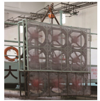
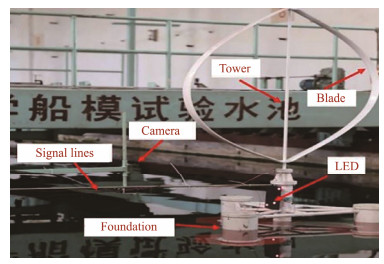
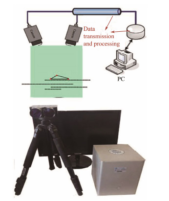
4.1 Model Test ConfigurationThe model test was conducted in the Tianjin University wave tank, which has dimensions of 3 m × 7 m × 137 m and is equipped with wind generation, wave generation, and measurement systems. The wind generation system, which comprises 3 × 3 fans, is shown in Fig. 5. An integrated dense screen was installed in front of the fans to improve the spatial uniformity and temporal stability of the wind. A 1/50 scale model (Fig. 6) was then established. The geometric similarity, gravity similarity, and the Strouhal number similarity, which represents the dynamic behaviors, were satisfied in the model test. The test conducted in this study emphasizes the substructures, such as the floating foundation. Consequently, the Froude number similarity is considered, while the Reynolds number similarity remains unsatisfied. The rotating blades comprised polypropylene plastic. The same NACA0018 airfoil section and parabolic offsets of the prototype model were adopted, as shown in Fig. 6. Detailed parameters are provided in Table 4. An optical motion measurement system (Fig. 7) was adopted to capture the wind turbine motion without the inertia influence of the equipment.
|
Fig. 5 Wind generation system. |
|
Fig. 6 Model configuration of the wind turbine model and measurement system. |
|
|
Table 4 Parameters of the wind turbine model |
|
Fig. 7 Optical motions measurement system. |
Another challenge in the model test is the mooring stiffness similarity. The mooring cable was used in the tests. The diameter of the steel rope was chosen on the basis of the geometric similarity rule. However, the weight similarity was not qualified when only adopting wire for the entire mooring cable. Therefore, a length of the micro anchor chain was added to increase the total weight. Moreover, a length of spring was included to meet the stiffness similarity. The parameters of the mooring lines are shown in Table 5.
|
|
Table 5 Mooring cable model parameters |
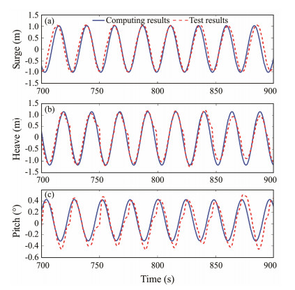
First, a series of tests under regular waves were conducted to obtain the response amplitude operators (RAOs) of the semi-buoy. The wind turbine was in a parked state in these tests, and the time histories of surge, heave, and pitch motions were captured. Simultaneously, the foundation motion was also calculated on the basis of the aero-hydro-mooring coupled code under the same scenario. Both results are displayed in Fig. 8. Comparison of the time histories revealed that the surge and heave results have a good agreement. Considering pitch motion, the amplitude of the experimental results has a slight difference compared with the prediction of the in-house code.
|
Fig. 8 Time histories of floating foundation motions (prototype wave period = 24 s). (a), Surge; (b), Heave; (c), Pitch. |
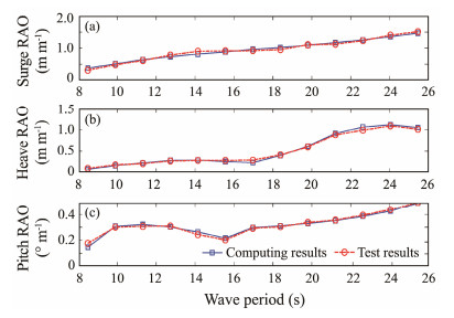
The RAOs in surge, heave, and pitch motions are calculated and displayed in Fig. 9 to further verify the accuracy of the code. The results show that the numerical simulation curves agree well with experimental ones. Notably, the wave period ranges from 1.2 s to 3.6 s due to the limitation of the wave generator in the tank. Therefore, the corresponding wave period range is from 8.5 s to 25.5 s in the prototype scale, as shown in Fig. 9. The two RAO curves are almost identical; thus, the accuracy of the hydrodynamic module could be validated.
|
Fig. 9 RAOs of semi-submersible floating foundation. |
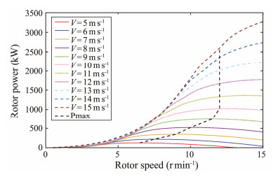
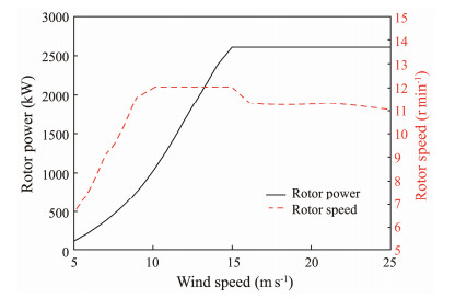
Rotor power and rotating torque are not tested in the present model tests due to the limitation of the water tank laboratory. The aerodynamic calculation method used in the code refers to a previous work, which has been validated by Liu et al. (2017b). Moreover, the rotor speed controlling strategy is an important issue in the power production progress. The rotational speed should be adjusted in accordance with the inflow wind speed to obtain rated output power in different scenarios. The output power is calculated under different rotational and wind speeds. The rotational speed under different wind speeds is classified into four parts based on the results displayed in Fig. 10. The wind turbine initially remains parked when the wind speed is less than 5 m s−1. The rotational speed is set to obtain maximum output power according to the Pmax curve shown in Fig. 10 when the wind speed ranges from 5 m s−1 to 10 m s−1. The rated rotational speed 12 r min−1 is then adopted when the wind speed ranges from 10 m s−1 to the rated speed of 15 m s−1. Considering the over rated wind speed, the control strategy is applied to maintain rated output power. Thus, the rotor speed and output power under different wind speed scenarios are shown in Fig. 11.
|
Fig. 10 Output power under different rotational and wind speeds. |
|
Fig. 11 Power and rotational speed under different wind speeds. |
After the validation process in Section 4, numerical simulation is conducted on the basis of the code in this section, and the dynamic response of the VAWT is investigated under various scenarios. First, free decay tests are conducted to obtain the natural periods of surge, heave, and pitch motion. Then, three regular scenarios from LC 1.1 to 1.3 are defined as cut-in, rated, and cut-out conditions under regular waves. Afterward, three additional irregular wave conditions, which are defined as cases LC 2.1 to 2.3, are considered. The details of environmental parameters are presented in Table 6. Notably, steady wind is considered in regular and irregular scenarios.
|
|
Table 6 Regular and irregular scenarios (LCs 1 and 2) |
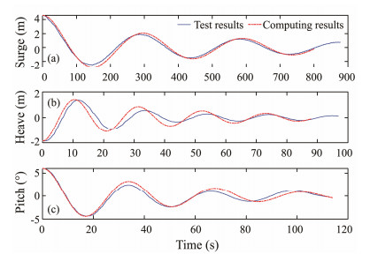
A series of free decay tests are conducted in clam water to obtain natural frequencies and damping coefficients of the wind turbine. An initial disturbance is prescribed in surge, heave, and pitch motion, and the VAWT is then released freely to obtain the free decay time histories, as shown in Fig. 12. The natural frequencies of the corresponding DOF according to the fast Fourier transformation are shown in Table 7.
|
Fig. 12 Free decay curves of the wind turbine. |
|
|
Table 7 Natural frequencies of scaled VAWT model |
The damping coefficients are acquired from extinction curves (Pegalajar-Jurado et al., 2018). The adjacent amplitudes are collected to plot the extinction curves for each DOF. Linear and quadratic damping coefficients can be obtained in accordance with the extinction curves, as shown in Table 8.
|
|
Table 8 Damping coefficient |
The relaxation tests could be performed numerically by applying the damping coefficients to the numerical model. The recorded time histories are also displayed in Fig. 12. The obtained findings indicate that the simulation results generally agree well with the model tests. However, the amplitudes of each oscillation cycle still demonstrate minor differences between the two results. This phenomenon may be attributed to the motion capture during the model tests. The motion is ideally decayed in numerical simulations due to damping effects. By contrast, the decay of the experimental amplitudes does not strictly follow the quadric relationship represented by the fitted curve. This phenomenon may be due to the precision of the model and error of motion capture devices, which leads to the minor difference between the amplitude results.
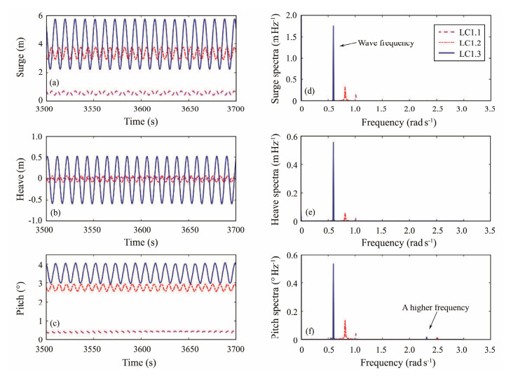
5.2 Regular Wave ScenariosThe motions of VAWTs under regular waves and wind, including surge, heave, and pitch, are investigated in this section. A 4600 s duration and 0.1 s step simulation is performed for each load case. Fig. 13 shows the time histories and response spectra in cases LC 1.1, 1.2, and 1.3. The VAWT oscillates in wave frequency. Thus, wave is the dominant factor of VAWT motions under regular wave cases.
|
Fig. 13 Time histories and amplitude spectra under regular wave scenarios. |
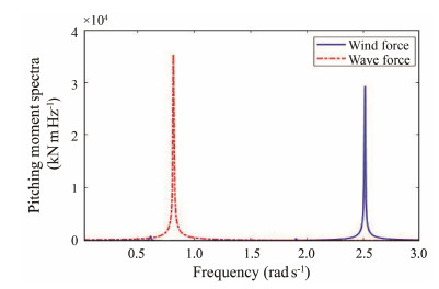
Moreover, the pitch spectra in Fig. 13(f) revealed not only the existence of wave frequencies in the pitch response but also a high frequency component in all three cases. The time histories of wind and wave forces in the pitch direction under LC 1.2 were extracted to further study this effect. The fast Fourier transformation was then conducted, and the amplitude spectra results are displayed in Fig. 14. Comparison of the frequencies revealed that the high frequency shown in Fig. 13 is in accordance with the peak frequency of the wind load, which originated from the rotation of the wind turbine. The rotor researched in this work has two blades; these blades rotate and thus produce a 2P frequency, which is twice the rotor speed. Notably, although the amplitude of wind loads is only approximately one-third less than that of wave loads, the pitch amplitude of wind load frequency is substantially smaller than that of wave frequency. Thus, the aerodynamic loads on the rotating blades induce high frequency response, but their effect on the pitch motion of the wind turbine is considerably less than the wave effect.
|
Fig. 14 Spectra of wind and wave forces in pitch direction under LC 1.2. |
The dynamic responses of VAWTs under irregular waves and steady wind are examined in this subsection. The irregular scenarios (Table 6) are adopted to perform the simulations. The simulation duration and time step are similar to those of the regular cases. The numerical results are first investigated, and then the effects of second-order wave load are further discussed.
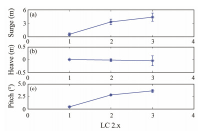
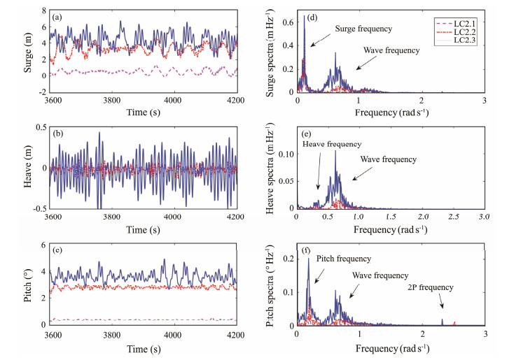
5.3.1 Numerical ResultsThe dynamic responses of the floating VAWT are evaluated considering first- and second-order wave forces. The statistical results of surge, heave, and pitch motions are displayed in Fig. 15, and the time histories and spectra are presented in Fig. 16.
|
Fig. 15 Statistical results of the floater motion under irregular wave scenarios. |
|
Fig. 16 Time histories and response spectra under irregular wave scenarios. |
The spectra in Fig. 16 indicate that the heave motion of VAWT is dominated by the wave force, and its response is mainly distributed as the wave frequencies. The low-frequency components, which have larger peaks than the wave frequency components, could be observed for surge and pitch motions. This condition is recognized as the influence of second-order wave load, which will be specifically discussed in the following subsection.
Moreover, comparison of the pitch response spectra in Figs. 13(f) and 16(f) revealed another interesting phenomenon, that is, the 2P frequency component in pitch motion under irregular scenarios has a larger peak than those under regular wave cases. The absolute amplitudes of 2P response remained almost the same in the two above-mentioned cases. The absolute 2P response remains at a similar level. However, the relative proportion of the 2P response is enlarged due to the wave energy distribution in a certain range under irregular cases. Hence, although the 2P frequency component is negligible under the regular wave, 2P frequency from the rotor has a certain effect on pitch motions of the wind turbine and should be considered in the design of floating VAWTs for real offshore environments with irregular waves.
5.3.2 Effect of the Second-Order Wave ForceThe second-order wave forces are relatively smaller compared with the first-order wave forces. However, the second-order wave forces have an important effect on the dynamic responses of the floating wind turbines. Pinkster (1975) indicates that the second-order wave forces could be categorized into the following five parts:
| $ {\overrightarrow F _{\sec }} = - \frac{1}{2}\rho g\oint\limits_{WL} {\zeta _r^{(1)} \cdot \zeta _r^{(1)}\vec n{\text{d}}l} {\text{ + }}\frac{1}{2}\rho \iint\limits_{{S_0}} {\left[ {\nabla {\Phi _1} \cdot \nabla {\Phi _1}} \right]\vec n{\text{d}}S} + \\ \rho \iint\limits_{{S_0}} {\left[ {{{\overrightarrow X }^{(1)}} \cdot \nabla \frac{{{\text{d}}{\Phi ^{(1)}}}}{{{\text{d}}t}}} \right]\vec n{\text{d}}S}{\text{ + }}m \cdot x_5^{\left(1 \right)} \cdot \ddot x_3^{\left(1 \right)} + \rho \iint\limits_{{S_0}} {\frac{{{\text{d}}{\Phi _2}}}{{{\text{d}}t}}\vec n{\text{d}}S}, $ | (2) |
where ρ is the water density, g is the gravitational acceleration,
The first four terms of Eq. (2) are the mean drift force related to the first-order solution, while the fifth term is based on the contribution of the second-order velocity potential. SESAM software was utilized in the present research to calculate the second-order wave forces, in which the full QTF method was applied.
Two cases are adopted under the irregular scenario LC 2.2 to investigate the inherent dynamics of the slow-drift motions of surge and pitch. Only the first-order wave load is taken in the simulation in the first case, while first- and second-order wave loads are adopted for the other case. Time histories and spectra of surge, heave, and pitch motions are displayed in Fig. 17.

|
Fig. 17 Time histories and response spectra under the cases of first-order wave force and first-order + second-order wave force. |
Fig. 17 shows that the low-frequency components represent the natural frequencies of each DOF. Surge and pitch motions have natural frequency components under the case without second-order wave loads, while this phenomenon is not observed in heave motion. The low-frequency responses in surge, heave, and pitch are all excited considering the second-order wave loads. However, the amplitude of low-frequency components in heave motion is still lower than that of wave frequency components. The motions induced by the second-order wave loads may have a negative influence on the safety and lifespan of the wind turbine structure. Thus, considering the second-order wave loads when predicting the dynamic responses of the floating VAWTs is necessary.
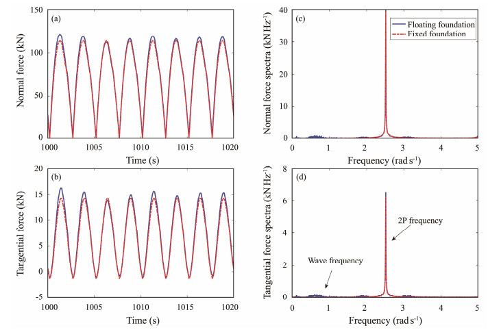
5.4 Effect of the Floater Motions on Aerodynamic LoadsThe aerodynamic performance of floating HAWTs is dependent on the motions of the buoy according to previous research (Li et al., 2017a). The effect of the buoy motions on the aerodynamic performance of floating VAWTs is also investigated in this subsection. Fixed and floating VAWTs are taken as examples, and their aerodynamic loads are calculated under LC 2.2 for comparison. The time histories and response spectra of the tangential and normal forces on the rotating blades are displayed in Fig. 18.
|
Fig. 18 Aerodynamic forces of the floating VAWT under floating and fixed conditions. |
The amplitudes of aerodynamic loads under fixed and floating cases have minor differences according to the time histories in Fig. 18. Specifically, compared with the results of the fixed case, the amplitudes of normal and tangential forces under the floating case respectively increased by 7.1% and 19.4%. By contrast, the spectra in Fig. 18 show that the oscillations of aerodynamic loads have minimal differences among the two cases. The wave frequency component exists in the floating case, but its amplitude is substantially smaller compared with that of aerodynamic frequency 2P. Overall, the buoy motion has minimal effects on the oscillations of aerodynamic loads of the floating VAWT.
6 ConclusionsAn aero-hydro-mooring coupled dynamic model is adopted in time domain to investigate the dynamic responses of semi-submersible floating VAWTs. This model contains the following: an aerodynamic model based on double-multiple stream tube theory, a wave model considering the second-order wave force based on 3D potential theory, and a mooring model based on catenary theory. Specifically, a water tank model test is conducted to validate the accuracy of the hydrodynamic model.
The motions of the floating VAWT are assessed by the numerical simulations considering the regular/irregular wave and wind loads. Results show that wave is the dominant factor of the VAWT motions. For regular wave scenarios, except for the wave frequency component, a 2P frequency, which originates from the rotation of the wind turbine, could be observed in pitch motion despite its small size. Compared with the regular wave cases, the response frequencies of the floating VAWT in irregular waves are remarkably complicated. Natural frequencies of the wind turbine in surge, heave, and pitch are also excited by irregular wave forces, and the 2P responses in pitch motion are evident.
Furthermore, the effect of the second-order wave force on the motions of the floating VAWT is assessed. The low-frequency responses for the surge and pitch motions are markedly excited with the addition of the second-order wave force, but the amplitude of low-frequency components in the heave motion is relatively small. The second-order wave forces should generally be included when predicting dynamic responses of the semi-submersible VAWT. The effect of buoy motions on aerodynamics is also investigated. The aerodynamic force of the rotor is compared under floating and fixed VAWT cases. The results show that the buoy motion has minimal effects on the oscillations of aerodynamic loads.
Notably, only the test results without wind are compared with the numerical simulation to verify the dynamic performance due to the limitation of the wave tank. In subsequent research, the numerical results presented by other researchers, such as Cheng et al.(2016, 2019) and Collu et al. (2014), may be used in subsequent research to verify the coupled method. Furthermore, CFD and a further experiment design considering wind loads may be of considerable importance.
Moreover, the aero-hydro-mooring coupled code proposed in the current study needs improvement. On the one hand, the wave-body interaction is simulated on the basis of 3D potential theory in the frequency domain and is further transferred into the time-domain equation according to the Cummins equation. The direct hydrodynamic calculations in real time, such as the boundary element method, or other computational fluid approaches, will be introduced in future work (Li, 2015; Li and Liu, 2018; Li et al., 2019). On the other hand, slender bodies, such as blades and the tower, vibrate under the wind turbine operation, which may affect the dynamic response as well as the aerodynamic loads on the structure. The flexibility of these structures is not included in the present study. Further simulations regarding the elastic effects are needed to analyze these issues comprehensively.
AcknowledgementsThe study is supported by the National Natural Science Foundation of China (No. 51879190), and the Tianjin Research Innovation Project for Postgraduate Students (No. 2021YJSB185).
API RP-2SK, 2005. Design and Analysis of Station Keeping Systems for Floating Structures. American Petroleum Institute, Washington D. C., USA, 66-67.
(  0) 0) |
Borg, M., and Collu, M., 2015. Frequency-domain characteristics of aerodynamic loads of offshore floating vertical axis wind turbines. Applied Energy, 155: 629-636. DOI:10.1016/j.apenergy.2015.06.038 (  0) 0) |
Borg, M., Collu, M., and Kolios, A., 2014a. Offshore floating vertical axis wind turbines, dynamics modelling state of the art. Part Ⅱ: Mooring line and structural dynamics. Renewable and Sustainable Energy Reviews, 39: 1226-1234. DOI:10.1016/j.rser.2014.07.122 (  0) 0) |
Borg, M., Shires, A., and Collu, M., 2014b. Offshore floating vertical axis wind turbines, dynamics modelling state of the art. Part Ⅰ: Aerodynamics. Renewable and Sustainable Energy Reviews, 39: 1214-1225. DOI:10.1016/j.rser.2014.07.096 (  0) 0) |
Bruinsma, N., Paulsen, B. T., and Jacobsen, N. G., 2018. Validation and application of a fully nonlinear numerical wave tank for simulating floating offshore wind turbines. Ocean Engineering, 147: 647-658. DOI:10.1016/j.oceaneng.2017.09.054 (  0) 0) |
Cao, H., 2012. Study on the hydrodynamic performance of semi-submersible floating foundation of offshore wind turbine. Master thesis. Tianjin University, Tianjin (in Chinese).
(  0) 0) |
Cheng, Z., Madsen, H. A., Gao, Z., and Moan, T., 2016. Numerical study on aerodynamic damping of floating vertical axis wind turbines. Journal of Physics: Conference Series, 753(10): 102001. (  0) 0) |
Cheng, Z., Wen, T. R., Ong, M. C., and Wang, K., 2019. Power performance and dynamic responses of a combined floating vertical axis wind turbine and wave energy converter concept. Energy, 171: 190-204. DOI:10.1016/j.energy.2018.12.157 (  0) 0) |
Collu, M., Brennan, F. P., and Patel, M. H., 2014. Conceptual design of a floating support structure for an offshore vertical axis wind turbine: The lessons learnt. Ships and Offshore Structures, 9(1): 3-21. DOI:10.1080/17445302.2012.698896 (  0) 0) |
Coulling, A. J., Goupee, A. J., Robertson, A. N., Jonkman, J. M., and Dagher, H. J., 2013. Validation of a FAST semi-submersible floating wind turbine numerical model with DeepCwind test data. Journal of Renewable and Sustainable Energy, 5(2): 023116. DOI:10.1063/1.4796197 (  0) 0) |
Dixon, K., Ferreira, C. J. S., Hofemann, C., Bussel, G. J. W. V., and Kuik, G. A. M. V., 2008. A 3D unsteady panel method for vertical axis wind turbines. The Proceedings of the European Wind Energy Conference & Exhibiti on EWEC Brussels, 6: 1-10. (  0) 0) |
Dong, X., Lian, J., Wang, H., Yu, T., and Zhao, Y., 2018. Structural vibration monitoring and operational modal analysis of offshore wind turbine structure. Ocean Engineering, 150: 280-297. DOI:10.1016/j.oceaneng.2017.12.052 (  0) 0) |
Dyachuk, E., and Goude, A., 2015. Simulating dynamic stall effects for vertical axis wind turbines applying a double multiple streamtube model. Energies, 8(2): 1353-1372. DOI:10.3390/en8021353 (  0) 0) |
Eriksson, S., Bernhoff, H., and Leijon, M., 2008. Evaluation of different turbine concepts for wind power. Renewable and Sustainable Energy Reviews, 12(5): 1419-1434. DOI:10.1016/j.rser.2006.05.017 (  0) 0) |
Gao, Y., Li, C., and Cheng, X., 2013. Research on foundation response of a tri-floater offshore wind turbine. IOP Conference Series: Materials Science and Engineering, 52: 052009. DOI:10.1088/1757-899X/52/5/052009 (  0) 0) |
González, J. S., Payán, M. B., and Santos, J. M. R., 2018. Optimal design of neighbouring offshore wind farms: A co-evolutionary approach. Applied Energy, 209: 140-152. DOI:10.1016/j.apenergy.2017.10.120 (  0) 0) |
Goude, A., and Bülow, F., 2013. Robust VAWT control system evaluation by coupled aerodynamic and electrical simulations. Renewable Energy, 59: 193-201. DOI:10.1016/j.renene.2013.03.038 (  0) 0) |
Hall, M., and Goupee, A., 2015. Validation of a lumped-mass mooring line model with DeepCwind semisubmersible model test data. Ocean Engineering, 104: 590-603. DOI:10.1016/j.oceaneng.2015.05.035 (  0) 0) |
Hall, M., Buckham, B., and Crawford, C., 2014. Evaluating the importance of mooring line model fidelity in floating offshore wind turbine simulations. Wind Energy, 17(12): 1835-1853. DOI:10.1002/we.1669 (  0) 0) |
Han, Z., 2016. Design and dynamic analysis of semi-submersible offshore vertical axis wind turbine. Master thesis. Tianjin University, Tianjin (in Chinese).
(  0) 0) |
Hou, P., Enevoldsen, P., Hu, W., Chen, C., and Chen, Z., 2017. Offshore wind farm repowering optimization. Applied Energy, 208: 834-844. DOI:10.1016/j.apenergy.2017.09.064 (  0) 0) |
Kumar, R., Raahemifar, K., and Fung, A. S., 2018. A critical review of vertical axis wind turbines for urban applications. Renewable and Sustainable Energy Reviews, 89: 281-291. DOI:10.1016/j.rser.2018.03.033 (  0) 0) |
Lei, H., Su, J., Bao, Y., Chen, Y., Han, Z., and Zhou, D., 2019. Investigation of wake characteristics for the offshore floating vertical axis wind turbines in pitch and surge motions of platforms. Energy, 166: 471-489. DOI:10.1016/j.energy.2018.10.101 (  0) 0) |
Lei, H., Zhou, D., Bao, Y., Chen, C., Ma, N., and Han, Z., 2017. Numerical simulations of the unsteady aerodynamics of a floating vertical axis wind turbine in surge motion. Energy, 127: 1-17. DOI:10.1016/j.energy.2017.03.087 (  0) 0) |
Li, C., 2015. Numerical investigation of a hybrid wave absorption method in 3D numerical wave tank. CMES: Computer Modeling in Engineering & Sciences, 107(2): 125-153. (  0) 0) |
Li, C., and Liu, Y., 2018. On the weakly nonlinear seakeeping solution near the critical frequency. Journal of Fluid Mechanics, 846: 999-1022. DOI:10.1017/jfm.2018.322 (  0) 0) |
Li, C., Bryce, K. C., Liu, Y., and Yue, D. K. P., 2019. A fast multi-layer boundary element method for direct numerical simulation of sound propagation in shallow water environments. Journal of Computational Physics, 392: 694-712. DOI:10.1016/j.jcp.2019.04.068 (  0) 0) |
Li, H., Hu, Z., Wang, J., and Meng, X., 2018a. Short-term fatigue analysis for tower base of a spar-type wind turbine under stochastic wind-wave loads. International Journal of Naval Architecture and Ocean Engineering, 10(1): 9-20. DOI:10.1016/j.ijnaoe.2017.05.003 (  0) 0) |
Li, Y., Liu, L., Zhu, Q., Guo, Y., Hu, Z., and Tang, Y., 2018b. Influence of vortex-induced loads on the motion of SPAR-type wind turbine: A coupled aero-hydro-vortex-mooring investigation. Journal of Offshore Mechanics and Arctic Engineering, 140(5): 051903. DOI:10.1115/1.4040048 (  0) 0) |
Li, Y., Tang, Y., Zhu, Q., Qu, X., Wang, B., and Zhang, R., 2017a. Effects of second-order wave forces and aerodynamic forces on dynamic responses of a TLP-type floating offshore wind turbine considering the set-down motion. Journal of Renewable and Sustainable Energy, 9(6): 63302. DOI:10.1063/1.5007893 (  0) 0) |
Li, Y., Tang, Y., Zhu, Q., Qu, X., Zhai, J., and Zhang, R., 2017b. Feasibility analysis of floating offshore wind turbine with single point mooring system. The 27th International Ocean and Polar Engineering Conference. San Francisco, California, ISOPE-I-17-558.
(  0) 0) |
Li, Y., Zhu, Q., Liu, L., and Tang, Y., 2018c. Transient response of a SPAR-type floating offshore wind turbine with fractured mooring lines. Renewable Energy, 122: 576-588. DOI:10.1016/j.renene.2018.01.067 (  0) 0) |
Liu, L., Guo, Y., Jin, W., and Yuan, R., 2017a. Motion performances of a 5 MW VAWT supported by spar floating foundation with heave plates. ASME 2017 36th International Conference on Ocean, Offshore and Arctic Engineering. American Society of Mechanical Engineers. Trondheim, Norway, OMAE2017-62625.
(  0) 0) |
Liu, L., Guo, Y., Zhao, H., and Tang, Y., 2017b. Motions of a 5 MW floating VAWT evaluated by numerical simulations and model tests. Ocean Engineering, 144: 21-34. DOI:10.1016/j.oceaneng.2017.08.004 (  0) 0) |
Liu, S. Y., and Ho, Y. F., 2016. Wind energy applications for Taiwan buildings: What are the challenges and strategies for small wind energy systems exploitation. Renewable and Sustainable Energy Reviews, 59: 39-55. DOI:10.1016/j.rser.2015.12.336 (  0) 0) |
Liu, Y., Xiao, Q., Incecik, A., Peyrard, C., and Wan, D., 2017c. Establishing a fully coupled CFD analysis tool for floating offshore wind turbines. Renewable Energy, 112: 280-301. DOI:10.1016/j.renene.2017.04.052 (  0) 0) |
Mandal, A. C., and Burton, J. D., 1994. The effects of dynamic stall and flow curvature on the aerodynamics of darrieus turbines applying the cascade model. Wind Engineering, 18: 267-282. (  0) 0) |
Masciola, M., Jonkman, J., and Robertson, A., 2013. Implementation of a multisegmented, quasi-static cable model. The Twenty-third International Offshore and Polar Engineering Conference. Anchorage, Alaska, ISOPE-I-13-127.
(  0) 0) |
Murray, J., and Barone, M., 2011. The development of cactus, a wind and marine turbine performance simulation code. The 49th AIAA Aerospace Sciences Meeting Including the New Horizons Forum and Aerospace Exposition. Orlando, Florida, AIAA 2011-147.
(  0) 0) |
Paraschivoiu, I., 2002. Wind Turbine Design: With Emphasis on Darrieus Concept (Chapter 4). Presses internationals Polytechnique. Montreal, Canada, 438pp.
(  0) 0) |
Pegalajar-Jurado, A., Bredmose, H., Borg, M., Straume, J. G., Landbø, T., Andersen, H. S., et al., 2018. State-of-the-art model for the LIFES50+ OO-Star Wind Floater Semi 10 MW floating wind turbine. Journal of Physics: Conference Series, 1104: 012024. DOI:10.1088/1742-6596/1104/1/012024 (  0) 0) |
Pinkster, J. A., 1975. Low-frequency phenomena associated with vessels moored at sea. Society of Petroleum Engineers Journal, 15: 487-494. DOI:10.2118/4837-PA (  0) 0) |
Salehyar, S., Li, Y., and Zhu, Q., 2017. Fully-coupled time-domain simulations of the response of a floating wind turbine to non-periodic disturbances. Renewable Energy, 111: 214-226. DOI:10.1016/j.renene.2017.04.017 (  0) 0) |
Shires, A., 2013. Development and evaluation of an aerodynamic model for a novel vertical axis wind turbine concept. Energies, 6(5): 2501-2520. DOI:10.3390/en6052501 (  0) 0) |
Tjiu, W., Marnoto, T., Mat, S., Ruslan, M. H., and Sopian, K., 2015. Darrieus vertical axis wind turbine for power generation Ⅱ: Challenges in HAWT and the opportunity of multi-megawatt Darrieus VAWT development. Renewable Energy, 75: 560-571. DOI:10.1016/j.renene.2014.10.039 (  0) 0) |
Wendler, R., Calderón-Muñoz, W. R., and Leboeuf, R., 2016. Energy-based iteration scheme of the double-multiple streamtube model in vertical-axis wind turbines. Acta Mechanica, 227(11): 1-9. (  0) 0) |
Wong, K. H., Chong, W. T., Sukiman, N. L., Poh, S. C., Shiah, Y. C., and Wang, C. T., 2017. Performance enhancements on vertical axis wind turbines using flow augmentation systems: A review. Renewable and Sustainable Energy Reviews, 73: 904-921. DOI:10.1016/j.rser.2017.01.160 (  0) 0) |
 2023, Vol. 22


