2) Key Laboratory of Marine Environment and Ecology, Ministry of Education, Ocean University of China, Qingdao 266100, China;
3) 801 Institute of Hydrogeology and Engineering Geology, Shandong Provincial Bureau of Geology & Mineral Resources, Jinan 250014, China;
4) Shandong Engineering Research Center for Environmental Protection and Remediation on Groundwater, Jinan 250014, China;
5) Zhangqiu Branch of Jinan Ecological Environment Bureau, Jinan 250200, China;
6) Solid Waste and Chemicals Management Center Ministry of Ecology and Environment, Beijing 100012, China
In recent years, due to the depletion of coal resources and the adjustment of China's industrial policy, a large number of coal mines have been abandoned or closed. After the coal mine is closed, the open system formed in the mining process is transformed into a closed or semi-closed system, and various pollutants left behind migrate into the deep groundwater system. Harmful substances from mines, coal-bearing strata, roadways and adjacent aquifers will enter the groundwater system, forming a new pollution source (Zhang et al., 2020). Some undesirable enterprises discharge industrial 'three wastes' directly into this closed system, which further aggravates the risk of pollution (Mukate et al., 2018; Zhang et al., 2022). The pollution incident reported in this article is of this type. Since this kind of pollution formed in the deep layer, it is difficult to detect until large-scale groundwater pollution events occur, which poses a great threat to the groundwater environment. In addition, due to the special geographical location for the coastal area of Shandong mining area, pollutants from industrial activities, waste discharge and improper disposal practices in the terrestrial environment, such as sewage, petroleum hydrocarbons, sediments and refuse, may also enter the ocean along with river water and other land-based runoff, posing a greater threat to marine ecosystems (Daoji and Daler, 2004). In the context of marine conservation, it is critical to consider the potential impacts of remediation efforts for deep pollution events on marine ecosystems.
According to engineering practices, after the occurrence of underground pollution incidents, the first step is to block the diffusion pathways of pollution. The establishment of an anti-seepage system to control harmful pollutants within a certain range is the most direct and effective measure to prevent and control pollution diffusion (Chen et al., 2021). Multiple instances demonstrate that the construction of vertical impervious body around the contaminated site by grouting and other technical methods has a good anti-seepage effect, with lower costs and easy to recover (Malusis and McKeehan, 2013; Xue, 2013; Huang et al., 2021; Sample-Lord et al., 2021). If no measures are taken to stop it, fault zones in geological structures and the presence of karst groundwater systems can serve as pathway for pollutants to migrate to broader inland or coastal waters, and even deep-sea aquifers, causing more widespread pollution. However, the blocking effect of different types and materials of cut-off walls on different types of pollutants, and the influence of the construction of cut-off walls on the change of groundwater flow field and on the restoration process is not clear (Liu et al., 2018; Xu et al., 2019).
After effectively blocking pollutants, the next step is to carry out pollutant treatment and site restoration. Although, some effective treatment technologies have been developed in the remediation of soil and groundwater pollution (Liu et al., 2024), such as ectopic remediation technology (Liang et al., 2021), which is mainly based on solidification stabilization and chemical oxidation, etc., and in-situ gas phase extraction (Guo et al., 2020; Zhang et al., 2020) and multiphase extraction (Chesnaux, 2008; Zhang et al., 2020). Soil vapor extraction, chemical oxidation, chemical reduction and in-situ thermal desorption are the current mainstream remediation technologies for organic contaminated sites (Liu, 2018; Zhu, 2018), but these technologies have their own advantages and disadvantages (Monier, 2010; Lim et al., 2016). The treatment effect is usually affected by external factors such as site conditions, groundwater distribution and temperature (Ossai et al., 2020; Cao et al., 2021), especially whether the secondary pollutants produced in the remediation process (Kumar et al., 2018; Chen et al., 2024).
In 2015, in the goaf collapse area of a coalfield in Shandong Province, China, the improper discharge of industrial waste liquid caused the multiphase organic pollution of water, gas and waste residue in the underground coal seam roadway at the depth of 80 m. The pollutants quickly polluted the shallow groundwater within the surrounding 13300 m2 range, and posed a potential threat to the deep confined aquifer. There are not only many roadways in the polluted area, but also the distribution of fault fracture zone and the geological conditions are complex. This pollution incident is currently the deepest underground pollution incident publicly reported in China. The disposal and restoration project lasted for 2 years. The engineering disposal methods mainly include the construction of pollutant diffusion blocking system, roadway pollution waste and solid waste excavation technology, roadway gas remediation technology and groundwater in-situ remediation technology. This paper will discuss the construction of pollutant blocking system and groundwater and gas remediation technology in this pollution incident, and evaluate the remediation effect by using the results of geochemical and geophysical exploration, with emphasis on the discussion and analysis of the problems existing in the remediation project. These works can provide reference for exploring effective engineering disposal methods of deep pollution events.
2 General Situation of Pollution IncidentIn October 2015, an illegal dumping incident occurred in a certain location in Jinan City, Shandong Province, China, involving the discharge of waste liquid into an abandoned coal mine, resulting in a fatal incident. The dumped waste liquid primarily consisted of toxic and hazardous substances such as chemical waste residue from the petrochemical industry, coke oven gas residue, and alkali residue. Following the pollution incident, the assessed accident well had a diameter of approximately 3 m and a depth of about 75 m, with around 700 m3 of solid waste distributed within it. The underground water in tunnels and goaf areas mainly contained pollutants exceeding standards, including dichloromethane and N-nitrosodiamine, covering an area of approximately 13300 m2. The restoration project involved the removal of about 40000 m3 of contaminated soil.
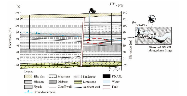
The polluted water in this study consists of the water from the mined-out water and roadway in the 10th-1 coal seam. The height of the roadway is about 2 m, which is full of water. The main water for replenishment layer comes from fissures in the upper bedrock. The mining layer (roadway layer) is located on the monoclinic structure below the groundwater level (buried depth 60 m), with a dip of NE 30°, a dip angle of 8° – 12°, and a stable strike, and the buried depth of the floor is between 75 m and 120 m. The accident well is located in the higher position of the coal seam in the south. There are complex coal mining roadways and goaf in the mining layer. On the north side of the accident well, there is a NE-trending fault with a dip angle of 10° – 15° and a dip of NNE. The geological model of the contaminated area is shown in Fig.1.
|
Fig. 1 (a) Geological model of polluted area. (b) Geological model of mining layer. |
The wastewater from the accident mine primarily affects the fissure water in shallow sandstone and thin-bedded limestone, which serves as the local residents' irrigation water source. When the fractured structure connects with the Ordovician limestone aquifer, it poses a threat to the karst groundwater of the Ordovician system. The Ordovician limestone serves as the drinking water source around the contaminated area, extensively exposed in the southern part of the polluted site, forming low hills with highly developed rock fractures. It receives significant replenishment from atmospheric precipitation and surface water, making it a recharge zone. The contaminated area is situated in the drainage area, with groundwater flow from south to north, while the discharge area below is characterized by a group of perennial springs.
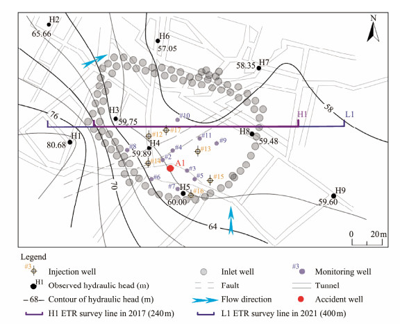
Immediately after the pollution incident, the curtain grouting method is used to intercept the pollution, and a concrete diaphragm wall is formed within 100 m around the accident well to isolate the pollutants from the surrounding area. According to the distribution range of roadway, fault and goaf and the characteristics of regional groundwater flow field, two rows of 61 grouting holes with a distance of 8 m and a single hole depth of 115 – 120 m are arranged in the downstream area of the north side of the fault, and 21 single-row grouting holes are arranged in the upstream area of the south side of the fault. The depth of single well is 75 – 90 m. One grouting hole is arranged at the branch of the connecting roadway of the accident well, and the distribution of the grouting hole is shown in Fig.2.
|
Fig. 2 Distribution of groundwater level and location of grouting curtain in polluted area. The circulating injection wells are #12, #13, #14, #15, #16, #17; the monitoring wells are #2, #3, #4, #5, #6, #7, #8, #9, #10, #11; the extraction well is accident well A1. |
According to the results of the previous investigation, the sites with high concentration of excessive pollutants in groundwater in the polluted area are all distributed within the range of grouting curtain. Therefore, the groundwater extraction treatment technology is directly used for the sites with low pollutant concentrations outside the waterproof curtain, while a combination of extraction technology and in-situ oxidation cycle extraction technology are used within the waterproof curtain. During the in-situ oxidation cycle extraction treatment of groundwater, the accident well (A1) is used as extraction well, where groundwater extraction equipment and water level on-line monitoring equipment are installed. Six circulation injection wells are installed within about 30 m around the accident well, along with in-situ oxidation circulating injection equipment. Ten monitoring wells are set up within a range of about 10 m around the extraction well. The water quality or water levels of extraction wells, cyclic injection wells and monitoring wells are analyzed regularly to evaluate the effect of in-situ oxidation cycle extraction treatment and provide guidance for the optimization of process parameters. During the restoration period, activated persulfate and modified Fenton oxidation agents were injected regularly into the circulating injection well at an injection flow rate of about 3 – 5 L min−1 and 1500 L d−1, and the concentrations were about 0.5% – 2%. The modified Fenton oxidizer is mainly composed of ferric ions (as catalyst) and hydrogen peroxide, and produces a large number of hydroxyl radicals through Fenton reaction (Fe2+ + H2O2 → Fe3+ + HO− + •OH). These hydroxyl radicals are highly oxidizing and can oxidize and degrade organic matters (Zhang, 2018). In addition, persulfate oxidants can also produce reactive oxygen species, which have strong oxidizing properties and promote the oxidative degradation of organic pollutants. After the successful in-situ oxidation cycle remediation of the groundwater, the construction of pH adjustment of groundwater is carried out to meet the limit requirements of Classes Ⅲ or Ⅳ of the groundwater quality standard (GBT-14848-2017).
The roadway gas contains over-standard pollutants such as toluene, dichloromethane and 1, 2-dichloroethane, and the repair project involves treating about 270000 m3 of gas. According to the physical properties of gaseous pollutants, the method of activated carbon adsorption is used. In order to ensure that the underground gas repair meets the required standard, the gas extraction points are mainly accident wells along the roadway, and at the same time, the underground gas at all well sites (the average distance between each point is about 10 m) is extracted, with emphasis on the targeted extraction treating areas where the underground gas levels exceeds the standard.
3 In-situ Detection of Engineering Repair Process 3.1 Chemical DetectionIn order to test the blocking effect of a grouting curtain project on pollutants and improve the basic data for onsite repair and treatment work, monitoring wells are set up in the contaminated areas to carry out real-time sampling and detection of pollutants in groundwater at different stages. The monitoring wells are arranged by a grid method, with a grid density of 20 m × 20 m, and a total of 96 wells. The designed diameter of the detection hole is 30 cm, and the drilling depth is 80 – 125 m, which allow the hole to reach the floor of the contaminated layer, about 2 m deep. The sampling is done at the bottom of the hole, and the detection parameters include pH, COD, ammonia nitrogen, VOCs (dichloromethane) and SVOCs (n-nitrosodi-n-pro-pylamine). The sampling and detection work were carried out before, during and after the repair treatment process.
The grid method is also used for roadway gas self-inspection and evaluation, with a grid size of 40 m × 40 m, focusing on roadway, collapsed goaf, broken zone and other areas. A total of 9 roadway gas sampling sites are arranged, and the sampling depth is about 60 m below the wellhead. The main detection index is VOCs (toluene, dichloromethane, 1, 2-dichloroethane). The sampling and detection work was also carried out before, during and after repair treatments.
3.2 Geophysical DetectionResistivity mapping method has been proved to be useful not only for underground pollution detection (Cataldo et al., 2014; Shao et al., 2019, 2021), but also for gas distribution detection in strata (Frid et al., 2014). In order to analyze the repair effect, resistivity mapping surveys were carried out before the start of the restoration project in 2017 and again 2 years after the completion of the field restoration project in 2021, with the same survey lines twice (Fig. 2). The E60DN resistivity detection system produced by China GeoPen Group is used in the two explorations, the Schronberg device is used as the detection devices, and the power supply current intensity is set to 1A. The difference is that the distance between the electrodes on the measuring line is 10 m in 2017, which is adjusted to 5 m in 2021 to increase the resolution of the detection profile. The data from both surveys are analyzed by nonlinear least square method using RES2DIVN software, and the inversion results are presented with the same color level system.
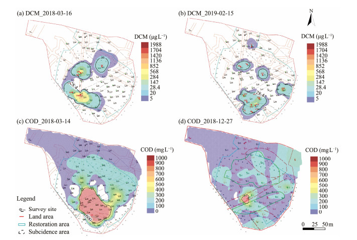
4 Analysis and Discussion of Test Results 4.1 Evaluation of Anti-Seepage Effect of Grouting CurtainFig.4 shows the detection results of dichloromethane (DCM) and COD in groundwater before the remediation treatment (March 2018) and during the remediation treatment (December 2018 and February 2019). The test results showed that before the restoration treatment, the dichloromethane level at only 6 sites exceeded the standard, which was 0.41 – 67.31 times of the limit. The over-pollution was mainly concentrated around the accident well, the roadway within the curtain, the broken zone and the subsidence area; during the process of repair, the overall concentration of dichloromethane decreased, but the number of abnormal points increased, distributed in isolated blocks within the curtain. The distribution characteristics of COD are different. Although the high concentration area of COD is mainly distributed around the accident well before repair treatment, it is widely distributed in the downstream direction, even beyond the control area of the cut-off wall to the north. During the repair process, the COD concentration decreased, but it was uniform across different areas within the curtain area.
|
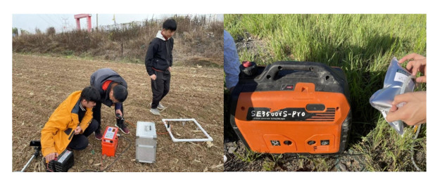
Fig. 3 A geophysical detection site. |
|
Fig. 4 Detection results of pollutants in groundwater at different stages. (a) and (c) are before remediation treatment; (b) and (d) are during the remediation process. |
Despite this, a high concentration zone still persisted beyond the control range of the cut-off walls in the north downstream direction. The monitoring results at different stages show that the cut-off walls in this project plays a good role in blocking the insoluble high-density organic pollutants, but it does not play a good role in blocking the diffusion of dissolved organic pollutants along the flow direction of groundwater. Instead, it only slows down the diffusion speed of pollutants to a certain extent.
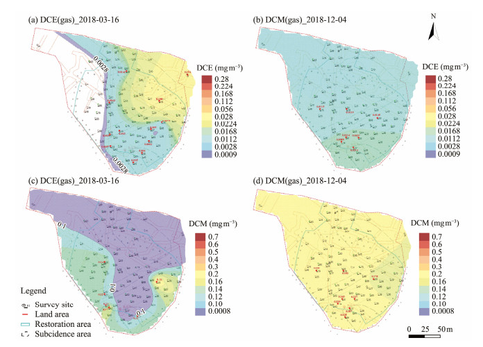
The influence of grouting curtain on the diffusion process of gaseous pollutants is more complex. Fig.5 shows the contents of dichloromethane (DCM) and dichloroethane (DCE) in the gas collected at a depth of 60 m during different periods before gas restoration. It can be seen from the image that in March 2018, gaseous dichloroethane was widely distributed on the north side of the contaminated site, with a high value area crossing the cut-off walls, indicating that the northern cut-off walls had a poor blocking effect on the diffusion process of gaseous dichloroethane. However, the high value area of gaseous dichloromethane is only distributed inside of the cut-off walls on the eastern and western sides, indicating that the cut-off walls effectively blocks its diffusion, although there is still a low concentration of gaseous dichloromethane in the north. By December 2018, the contents of gaseous dichloromethane and dichloroethane at the contaminated site increased and homogenized in varying degrees, and spread downstream across the cut-off waslls to the north. The increase in concentration can be attributed to the cyclic extraction and oxidation of groundwater during this period, making more liquid dichloromethane and dichloroethane volatilize into gaseous state and the generation of a large amount of gas during the oxidation process. The overall gas concentration within the site increased after being blocked by the cut-off walls and gas is unable to spread outward. Due to the good connectivity of the goaf where the contaminated site is located, the gas diffusion rate in all directions is relatively uniform, leading to homogenization. However, due to the poor blocking effect of the cut-off walls in the north, the gas spreads downstream under the action of groundwater flow field.
|
Fig. 5 Detection results of underground gaseous pollutants at different stages of remediation process. |
To sum up, it can be seen that the cement-soil cut-off wall has a good effect on blocking the diffusion of liquid and vapor phase pollutants in the EW direction. However, in the downstream of the groundwater flow field to the north, although double rows of grouting holes have been designed, it still does not block the diffusion of water-soluble organic pollutants and vapor phase pollutants. This is related to the lack of more reasonable grouting hole spacing and grouting materials because not fully considering the action intensity of groundwater flow field and pollutant diffusion characteristics in the design stage, as well as the quality of grouting construction.
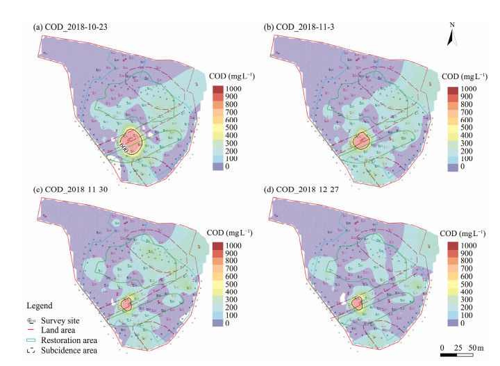
4.2 Evaluation of Groundwater Remediation EffectFig.6 shows the values of COD detected in different area of mine water during the extraction process of accident well groundwater (Figs.6a, b) and the process of in-situ oxidation treatment (Figs.6c, d).
|
Fig. 6 Changes of COD concentration distribution in groundwater during groundwater remediation. |
Figs.6a and 6b show that the extraction operation can rapidly reduce the distribution area and concentration of COD around the accident well. However, the scope of impact of this process is small, and there is no reduction of pollutants in distant areas. This consequence may be related to two factors: firstly, is that the accident well is located at the high water level, and the extraction construction does not form an obvious precipitation funnel, which makes the surrounding water converge to this point, as confirmed in the detection of groundwater level; secondly, although the contaminated stratum is in the goaf, the overall permeability is poor, and the fault structure and roadway do not play a good role in diversion. When it comes to the process of in-situ cyclic oxidation extraction, Fig. 6c shows that the high value distribution area of COD around the accident well continues to decrease, although the change is not significant. Meanwhile, the COD content in other locations of the contaminated area begins to decrease, especially in the north side of the contaminated site in the later stage of treatment (Fig.6d). The characteristic of this change is directly related to the degradation of the injected oxidizing agent diffusing into the contaminated site. It can be seen that both extraction and cyclic oxidation treatments play a role in the remediation process of deep groundwater pollution, the role of the former is to quickly reduce the content and distribution of pollutants from pollution sources, and restrain the continuous diffusion of pollution sources; the latter lies in the direct degradation of pollutants from pollution sources, and at the same time, it will be widely distributed in the polluted areas through diffusion to degrade pollutants in other locations. The faults and roadways in the polluted area play a certain role in promoting the diffusion of oxidants. The cut-off walls will affect the flow of groundwater, which has a negative effect on the diffusion of oxidizing agents. Therefore, in the implementation of the actual project, the design of the cut-off walls should comprehensively consider its blocking effect on pollutants and its influence on the implementation of some in-situ remediation methods.
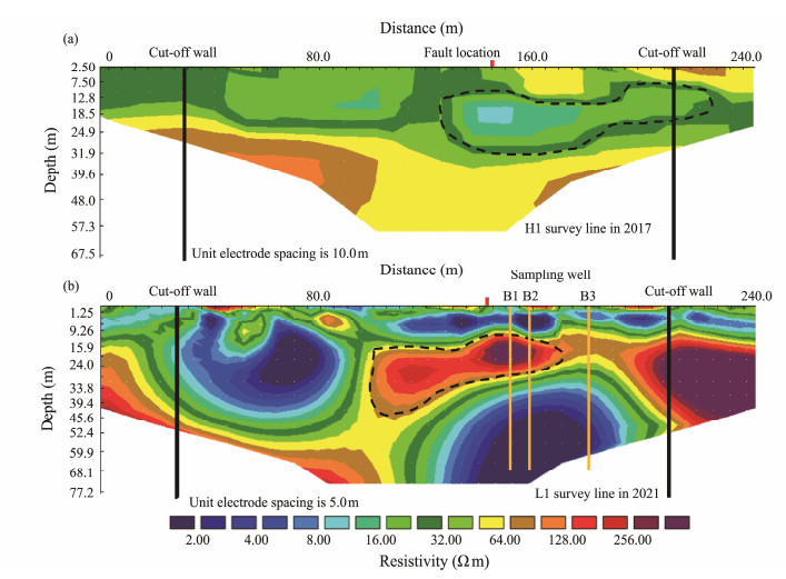
4.3 Secondary Pollution Caused by in-situ RemediationWe compare and analyze the resistivity mapping detection results at the same location before the site restoration treatment (2017) and two years after the completion of the restoration (2021) to determine the changes of formation conductivity in the restoration area, and then evaluate whether there are secondary pollutants. The inversion profile of detection resistivity in different periods is shown in Fig.7.
|
Fig. 7 Resistivity distribution along L1 line before and after site restoration. (a), detection profile before restoration treatment in 2017; (b), exploration profile after restoration treatment in 2021. |
Fig.7 shows that the electrical conductivity of the formation has changed obviously after the restoration treatment. Since the original stratum distribution and man-made engineering did not change during the two explorations, and the regional groundwater distribution did not change obviously, it can be inferred that the main reasons for the change of formation resistivity are as follows: 1) after restoration, the electrical conductivity of the pore water distributed in the Quaternary soil layer, the shallow karst water, the bedrock fissure water at the top of the goaf and the fault fissure water changed; 2) the enrichment characteristics of groundwater in the restoration area have changed; 3) there are secondary pollutants. According to this understanding, we propose that the shallow layered low resistivity anomaly area at a depth of 10 m in the exploration profile after restoration in 2021 is caused by the decrease in pore water conductivity and the increase in pore water content. The trap low resistivity abnormal areas on the left and right sides are caused by the construction of cut-off walls on both sides, which leads to the groundwater barrier and accumulation. Because the occurrence of strata in the field area is high in the west and low in the east, the distribution depth of the two abnormal areas is different. In the area located 100 – 240 m from the left end of the survey line and at the depth of 15 – 30 m, a low resistance abnormal area was observed before repair treatment, which transformed into a high resistance anomaly area after repair treatment. The regional geological data show that this area is a shallow karst development area, with a clayey soil cover and connection to an underlying fault. The characteristics of low resistance observed before restoration treatment should be related to the development of karst and high water content in this area. The high resistance anomaly after remediation may be related to the escape and accumulation of volatile organic pollutants, such as toluene, dichloromethane and dichloroethane, in the deep pollution zone after remediation.
In order to further explore the causes of the abnormal areas, we use three monitoring wells along the measuring line to collect gas and water samples and analyze the contents of pollutants in a high resistivity abnormal area and its surrounding position. The results show that the contents of gaseous dichloromethane and dichloroethane in the high resistivity abnormal area are significantly higher than those in the low resistivity abnormal area, and a large amount of CO2 concentrates in this area. This fully indicates that the abnormal area with high resistivity is the accumulation area of gaseous matters. The causes and mechanisms of shallow enrichment of gaseous pollutants will be analyzed in another article.
5 ConclusionsThe engineering disposal of deep multiphase multi-compound organic pollution events under complex geological conditions is a systematic project, and the system design should be carried out, comprehensively considering the characteristics of geology, hydrology and pollutant diffusion. The comprehensive treatment technology of blocking-sourcemulti-means in-situ remediation is adopted to prioritize different disposal projects and strictly follow the design and construction in order to achieve the desired results. The engineering practice reported in this paper has the following guiding significance for the effective development of pollution disposal project.
1) The pollutant diffusion blocking project plays an important role in preventing the expansion of pollution scope and ensuring the effective treatment of polluted areas. However, in addition to considering the groundwater flow field and the geological characteristics of the polluted area, the design of anti-seepage engineering should also take into account the differences in diffusion characteristics of different pollutants and the demand of groundwater flow field in the process of remediation and treatment, so as to achieve the relative balance between 'resistance' and 'conduction'.
2) The construction of the in-situ extraction and oxidation cycle extraction combination field is simple and effective for the treatment of deep organic pollutants. The former rapidly removes high concentration pollution sources, while the latter has an obvious effect on the removal of residual pollutants in a large area. However, the diffusion of oxidizer in the contaminated area requires the action of groundwater flow field. The completely blocked anti-seepage system is not conducive to the remediation process.
3) The generation of vapor phase pollutants in the multiphase compound organic pollution event is not only related to the direct pollution sources, but also the treatment process of liquid phase pollutants can promote the production of more vapor phase pollutants. The cut-off walls will make the vapor phase pollutants gather in the enclosed polluted area, and the concentration will increase rapidly. Therefore, the vapor phase pollutants should be treated after the liquid phase pollutants treatment. However, the blocking effect of cut-off walls project on gas diffusion is weaker than that of liquid phase pollutants, and the diffusion speed of vapor phase pollutants is fast and the distribution range is wide. So the multi-well synchronous extraction method should be adopted in the treatment process.
4) The disposal process of multiphase compound organic pollution events may make pollutants migrate and enrich to shallow strata in gaseous form through faults and other pathways, which need to be detected and analyzed comprehensively by means of geophysics after the restoration process and completion.
AcknowledgementsThe study is supported by the Polluted Site Remediation Project of Gao Village, Puji Street, Zhangqiu District, Jinan City, Shandong Province. This research is financially supported by the National Natural Science Foundation of China (Nos. 42072331, U1906209), and the Taishan Scholar Foundation (No. tstp20230626). We are especially grateful to the 801 Hydrogeology Engineering Geology Brigade of Shandong Bureau of Geology and Mineral Resources Exploration and Development for their support in the field investigation for this paper.
Author Contributions
All authors contributed to the study conception and design. Material preparation was performed by Xinyu Shi and Xiujun Guo. Investigation, data collection and data analysis were performed by Faming Wang, Yongyue Ma, Yuxiang Liu, Shanming Wei and Yu Wang. The draft of the manuscript was written by Jie Lu and Guantao Ding, and all authors commented on previous versions of the manuscript. All authors read and approved the final manuscript.
Data Availability
The data and references presented in this study are available from the corresponding author upon reasonable request.
Declarations
Ethics Approval and Consent to Participate
This article does not contain any studies with human participants or animals performed by any of the authors.
Consent for Publication
Informed consent for publication was obtained from all participants.
Conflict of Interests
The authors declare that they have no conflict of interests.
Cao, W., Zhang, L., Miao, Y., and Qiu, L., 2021. Research progress in the enhancement technology of soil vapor extraction of volatile petroleum hydrocarbon pollutants. Environmental Science – Processes & Impacts, 23(11): 1650-1662. (  0) 0) |
Cataldo, A., Persico, R., Leucci, G., De-Benedetto, E., Cannazza, G., Matera, L., et al., 2014. Time domain reflectometry, ground penetrating radar and electrical resistivity tomography: A comparative analysis of alternative approaches for leak detection in underground pipes. NDT & E International, 62: 14-28. (  0) 0) |
Chen, L., Ding, G., Lu, J., Liu, Y., Wei, S., Guo, X., et al., 2024. Gas tube effect: A transport mode of deeply buried volatile DNAPLs to shallow strata. Journal of Hydrology, 630: 130696. DOI:10.1016/j.jhydrol.2024.130696 (  0) 0) |
Chen, S., Chang, S., Wang, X., Wang, J., Zhang, Z. K., Pan, C. Y., et al., 2021. Emergency treatment technology and case study of sudden environmental pollution caused by oil spill in river basin. IOP Conference Series: Earth and Environmental Science, 621(1): 012143. DOI:10.1088/1755-1315/621/1/012143 (  0) 0) |
Chesnaux, R., 2008. Analytical closed-form solutions for assessing pumping cycles, times, and costs required for NAPL remediation. Environmental Geology, 55(7): 1381-1388. DOI:10.1007/s00254-007-1088-9 (  0) 0) |
Daoji, L., and Daler, D., 2004. Ocean pollution from land-based sources: East China Sea, China. Ambio, 1: 107-113. (  0) 0) |
Frid, V., Doudkinski, D., Liskevich, G., Shafran, E., Averbakh, A., Korostishevsky, N., et al., 2010. Geophysical-geochemical investigation of fire-prone landfills. Environmental Earth Sciences, 60(4): 787-798. DOI:10.1007/s12665-009-0216-0 (  0) 0) |
Guo, H., Qian, Y., Yuan, G. X., and Wang, C. X., 2020. Research progress on the soil vapor extraction. Journal of Groundwater Science and Engineering, 8(1): 57-66. (  0) 0) |
Huang, X., Li, J., Xue, Q., Chen, Z., Du, Y., Wan, Y., et al., 2021. Use of self-hardening slurry for trench cutoff wall: A review. Construction and Building Materials, 286: 122959. DOI:10.1016/j.conbuildmat.2021.122959 (  0) 0) |
Kumar, V., Shahi, S. K., and Singh, S., 2018. Bioremediation: An eco-sustainable approach for restoration of contaminated sites. In: Microbial Bioprospecting for Sustainable Development. Singh, J., et al., eds., Springer, Singapore, 115-136.
(  0) 0) |
Liang, J., Wang, S. J., Zhang, W. Y., Zhang, D., Zhang, Y., and Zou, H., 2021. Review on contaminated site remediation technologies in the USA and their revelation to China. Environmental Engineering, 39(6): 173-178. (  0) 0) |
Lim, M. W., Lau, E. V., and Poh, P. E., 2016. A comprehensive guide of remediation technologies for oil contaminated soilpresent works and future directions. Marine Pollution Bulletin, 109(1): 14-45. DOI:10.1016/j.marpolbul.2016.04.023 (  0) 0) |
Liu, L., Li, W., Song, W., and Guo, M., 2018. Remediation techniques for heavy metal-contaminated soils: Principles and applicability. Science of the Total Environment, 633: 206-219. DOI:10.1016/j.scitotenv.2018.03.161 (  0) 0) |
Liu, S., 2018. Geotechnical investigation and remediation for industrial contaminated site. Chinese Journal of Geotechnical Engineering, 40(1): 1-37. (  0) 0) |
Liu, Y., Fei, Y., Li, Y., Bao, X., and Zhang, P., 2024. Pollution source identification methods and remediation technologies of groundwater: A review. China Geology, 7(1): 125-137. (  0) 0) |
Malusis, M. A., and McKeehan, M. D., 2013. Chemical compatibility of model soil-bentonite backfill containing multiswellable bentonit. Journal of Geotechnical and Geoenvironmental Engineering, 139(2): 189-198. DOI:10.1061/(ASCE)GT.1943-5606.0000729 (  0) 0) |
Monier, A. L., 2010. Bench-scale studies of natural attenuation, biostimulation, and bioaugmentation for remediation of groundwater contaminated with benzene and toluene in the Piceance Basin, CO. Master thesis. Rice University.
(  0) 0) |
Mukate, S., Panaskar, D., Wagh, V., Muley, A., Jangam, C., and Pawar, R., 2018. Impact of anthropogenic inputs on water quality in Chincholi industrial area of Solapur. Maharashtra, India, Groundwater for Sustainable Development, 7: 359-371.
(  0) 0) |
Ossai, I. C., Ahmed, A., Hassan, A., and Hamid, F. S., 2020. Remediation of soil and water contaminated with petroleum hydrocarbon: A review. Environmental Technology & Innovation, 17: 100526. (  0) 0) |
Sample-Lord, K. M., Ahmed, M., and Malusis, M. A., 2021. Diffusion through soil-bentonite backfill from a constructed vertical cutoff wall. Soils and Foundations, 61: 429-443. (  0) 0) |
Shao, S., Gao, C., Guo, X., Wang, Y., Zhang, Z., Yu, L., et al., 2019. Mapping the contaminant plume of an abandoned hydrocarbon disposal site with geophysical and geochemical methods, Jiangsu, China. Environmental Science and Pollution Research, 26(24): 24645-24657. (  0) 0) |
Shao, S., Guo, X., Gao, C., and Liu, H., 2021. Quantitative relationship between the resistivity distribution of the by-product plume and the hydrocarbon degradation in an aged hydrocarbon contaminated site. Journal of Hydrology, 596: 126122. (  0) 0) |
Xu, H., Shu, S., Wang, S., Zhou, A., Jiang, P., Zhu, W., et al., 2019. Studies on the chemical compatibility of soil-bentonite cut-off walls for landfills. Journal of Environmental Management, 237: 155-162. (  0) 0) |
Xue, Q., Li, J. S., and Liu, L., 2013. Experimental study on antiseepage grout made of leachate contaminated clay in landfill. Applied Clay Science, 80: 438-442. (  0) 0) |
Zhang, C., 2018. Experimental study on in situ chemical oxidation remediation of 1, 2, 4-TCB pollution in groundwater. Master thesis. Nanjing University.
(  0) 0) |
Zhang, H., Xu, G., Zhan, H., Chen, X., Liu, M., and Wang, M., 2020. Identification of hydrogeochemical processes and transport paths of a multi-aquifer system in closed mining regions. Journal of Hydrology, 589: 125344. (  0) 0) |
Zhang, S. L., Xiao, M., and Wan, P., 2020. Soil vapor extraction international research status and developing trends. Environmental Ecology, 2(1): 69-75. (  0) 0) |
Zhang, X., 2020. Research progress in the organic contaminated sites remediation by in situ multi-phase extraction technology. Applied Chemical Industry, 49(1): 207-211 (in Chinese with English abstract). (  0) 0) |
Zhang, X., Zhang, S., Huang, T., and Jin, Z., 2022. Copper extraction from low-grade chalcopyrite in a bioleaching column assisted by bioelectrochemical system. Environmental Science and Pollution Research, 29(23): 35459-35470. (  0) 0) |
Zhu, D., 2018. Research on remediation methods of contaminated land and development trend. Environment, Resource and Ecology Journal, 2(1): 15-21. (  0) 0) |
 2025, Vol. 24


