2) Physical Oceanography Laboratory/CIMST, Ocean University of China and Qingdao National Laboratory for Marine Science and Technology, Qingdao 266100, China;
3) Department of mathematics, Changzhi University, Changzhi 046000, China
In tidal-dominated shallow seas, the tidal residual current controls the transport of the conservative substances beyond the time scale of tidal periods (Abbott, 1960; Nihoul and Ronday, 1975). Furthermore, the use of the Lagrangian velocity (uLR), instead of the Eulerian velocity (uE), is more appropriate in representing the mass transport. In weakly nonlinear systems, the first-order approximation of uLR is the mass transport velocity uL, first introduced by Longuet-Higgins (1969) in the study of wave-generated circulation in the open ocean. The governing equations for uL in a three-dimensional (3D) case were first derived by Feng (1987). The equations include the 'tidal body force' terms resulting from the nonlinear interaction of the zeroth-order tides. The governing equations reveal the dynamic factors contributing to uL; however, in practice, particle tracking is commonly used to obtain uLR (e.g., Zimmerman, 1979; Cheng and Casulli, 1982; Feng et al., 2008; Muller et al., 2009; Liu et al., 2012; Liang et al., 2014; Quan et al., 2014; Xu et al., 2016; Deng et al., 2017, 2019).
The analytic solution of uL is available for a few special cases (e.g., Ianniello, 1977, 1979; Winant, 2008; Jiang and Feng, 2011, 2014). In most other cases without available analytic solutions, numerical models are applied to solve uL (e.g., Wang et al., 1993; Sun et al., 2000, 2001; Liu et al., 2002; Lei et al., 2004; Wang et al., 2006). In early studies, the accuracy of the modeled uL was limited by the coarse spatial resolution of the models. Recently, Cui et al. (2019) assessed the accuracy of modeled uLfor the special case with analytic solution obtained previously by Jiang and Feng(2011, 2014). However, while the model and analytic solution show overall good agreement, the discrepancy remains noticeable.
In Cui et al. (2019), the tidal body force is computed by tidal-averaging the terms involving the time series of the tidal flow. In this process, the accuracy of the computed tidal body force is affected by errors related to discretization, numerical integration, and the open boundary condition, among others. In this study, we propose to compute the tidal body force using the harmonic constants of the tidal current obtained by performing a harmonic analysis of the tidal solution. After introducing the new method in Section 2, the solution of uL is first obtained for an elongated rectangular bay for comparison with the analytic solution of Jiang and Feng (2014) in Section 3. In Section 4, uL is calculated for a wide bay with different geometrical and physical parameters. The impacts of these parameters on uL are discussed. The conclusions from this study are summarized in Section 5.
2 Improved Computing Method for Solving uL 2.1 Governing EquationsThe governing equations of uL are the same as those in Feng (1987) and Cui et al. (2019). A summary of the key aspects is provided below. First, the equations are in nondimension form involving a parameter κ, which is the ratio of the tidal amplitude to the average water depth. In the weakly nonlinear case, i.e., O(κ) < 1, the tidal velocity and water elevation are presented as
| $u = {u_0} + \kappa {u_1} + O({\kappa ^2}), $ |
| $\zeta = {\zeta _0} + \kappa {\zeta _1} + O({\kappa ^2}), $ |
where u0 and
The residual water elevation ζE is defined as ζE = < ζ1 > , and the zeroth-order tidal displacement ξ0 is expressed as
| ${\xi _0} = (\xi, {\kern 1pt} {\kern 1pt} {\kern 1pt} \eta, {\kern 1pt} {\kern 1pt} {\kern 1pt} \varsigma) = \int_{{t_0}}^t {{u_0}(x, {\rm{ }}t')} {\rm{d}}t'.$ |
Meanwhile, the Eulerian residual velocity uE is defined as
| ${u_E} = ({u_E}, {v_E}, {w_E}) = (< {u_1} >, < {v_1} >, < {w_1} >) = < {u_1} > {\kern 1pt}, $ |
where the tidal-averaging operator is expressed as follows
| $ < \cdot > \; = \frac{1}{{nT}}\int_{{t_0}}^{{t_0} + nT} \cdot \;{\rm{d}}t.$ |
The mass transport velocity uL named by Longuet-Higgins (1969) is the sum of the Eulerian residual velocity and the Stokes' drift, i.e.
| ${u_L} = {u_E} + {u_S}, $ |
where the Stokes' drift uS is defined as
| ${u_S} = ({u_S}, \;{v_S}, \;{w_S}) = < {\xi _0} \cdot \nabla {u_0} >. $ |
The governing equations for the zeroth-order tidal motions are as follows:
| $\nabla \cdot {u_0} = 0, $ | (1) |
| $\frac{{\partial {u_0}}}{{\partial t}} - f{v_0} = - g\frac{{\partial {\zeta _0}}}{{\partial x}} + \frac{\partial }{{\partial z}}\left( {\upsilon \frac{{\partial {u_0}}}{{\partial z}}} \right){\kern 1pt}, $ | (2) |
| $\frac{{\partial {v_0}}}{{\partial t}} - f{u_0} = - g\frac{{\partial {\zeta _0}}}{{\partial y}} + \frac{\partial }{{\partial z}}\left( {\upsilon \frac{{\partial {v_0}}}{{\partial z}}} \right){\kern 1pt}, $ | (3) |
| $ z = 0, {w_0} = \frac{{\partial {\zeta _0}}}{{\partial t}};\frac{{\partial \left({{u_0}, {\kern 1pt} {\kern 1pt} {\kern 1pt} {v_0}} \right)}}{{\partial z}} = 0, $ | (4) |
| $ z = - h, {u_0} = 0;{v_0} = 0;{w_0} = 0. $ | (5) |
The governing equations for uL are as follows:
| $\nabla \cdot {u_L} = 0{\kern 1pt}, $ | (6) |
| $ -f{v_L} = - g\frac{{\partial {\zeta _E}}}{{\partial x}} + \frac{\partial }{{\partial z}}\left({\upsilon \frac{{\partial {u_L}}}{{\partial z}}} \right) + {\pi _x}, $ | (7) |
| $f{u_L} = - g\frac{{\partial {\zeta _E}}}{{\partial y}} + \frac{\partial }{{\partial z}}\left({\upsilon \frac{{\partial {v_L}}}{{\partial z}}} \right) + {\pi _y}, $ | (8) |
| $ z = 0, {w_L} = 0;\frac{{\partial \left({{u_L}, {\kern 1pt} {\kern 1pt} {\kern 1pt} {v_L}} \right)}}{{\partial z}} = 0, $ | (9) |
| $ z = - h, {u_L} = 0;{v_L} = 0;{w_L} = 0, $ | (10) |
| ${\pi _x} = - \frac{\partial }{{\partial z}}\left( {\upsilon \frac{{\partial < {\xi _0} \cdot \nabla {u_0} > }}{{\partial z}}} \right) - < {u_0} \cdot \nabla {u_0} > - f < {\xi _0} \cdot \nabla {v_0} > , $ | (11) |
| ${\pi _y} = - \frac{\partial }{{\partial z}}\left( {\upsilon \frac{{\partial < {\xi _0} \cdot \nabla {v_0} > }}{{\partial z}}} \right) - < {u_0} \cdot \nabla {v_0} > + f < {\xi _0} \cdot \nabla {u_0} >, $ | (12) |
where f, g, υ, and h are the non-dimensional Coriolis parameter, gravitational acceleration, vertical eddy viscosity coefficient, and water depth, respectively.
The tidal body force π = (πx, πy) (Eq. (11) and Eq. (12)) consists of three terms (Cui et al., 2019): π1 = (πx1, πy1) the vertical mixing of the Stokes' drift, π2 = (πx2, πy2) the contribution of the advection, and π3 = (πx3, πy3) the Coriolis effect of the local acceleration.
Eqs. (1)–(5) are commonly solved by using timestepping tidal models. Eqs. (6)–(12) can also be solved using the time-stepping method to reach a steady state (Cui et al., 2019). The key step is to compute the tidal body force terms (πx, πy).
2.2 Improving the Tidal Body Force ComputationIn Cui et al. (2019), the tidal body force (Eqs. (11) and (12)) was calculated by applying tidal-averaging over the nonlinearity coupled tidal solutions. In the current work, we propose an alternative approach. First, the HAMSOM model (Backhaus, 1985; Pohlmann, 1996, 2006) was applied to obtain the time series of the zeroth-order tidal variables at half hourly intervals over a period of 8 days. Then, the tidal harmonic analysis package T_TIDE (Pawlowicz et al., 2002) was applied to obtain the tidal amplitudes and phases from the time series. This procedure can effectively filter out the clutter other than the single-frequency tide input from the open boundary and suppress the noise that can introduce errors into the tidal body force.
The time series of the three components of tidal current are represented as
| ${u_0} = {A_u}\cos (\frac{{2{\rm{ \mathsf{ π} }}}}{T}t -{\varphi _u}), $ |
| ${v_0} = {A_v}\cos (\frac{{2{\rm{ \mathsf{ π} }}}}{T}t -{\varphi _v}), $ |
| ${w_0} = {A_w}\cos (\frac{{2{\rm{ \mathsf{ π} }}}}{T}t- {\varphi _w}), $ |
where Au, Av, Aw and φu, φv, φw are the amplitudes and phases of u0, v0, w0 respectively. The corresponding zeroth-order tidal displacements are expressed as
| ${\xi _0} = \frac{T}{{2{\rm{ \mathsf{ π} }}}}{A_u}[\sin (\frac{{2{\rm{ \mathsf{ π} }}}}{T}t- {\varphi _u}) + \sin ({\varphi _u})], $ |
| ${\kern 1pt} {\eta _0} = \frac{T}{{2{\rm{ \mathsf{ π} }}}}{A_v}[\sin (\frac{{2{\rm{ \mathsf{ π} }}}}{T}t- {\varphi _v}) + \sin ({\varphi _v})], $ |
| ${\varsigma _0} = \frac{T}{{2{\rm{ \mathsf{ π} }}}}{A_w}[\sin (\frac{{2{\rm{ \mathsf{ π} }}}}{T}t -{\varphi _w}) + \sin ({\varphi _w})].$ |
By substituting the above expressions into Eqs. (11) – (12), the tidal body force can be rewritten as
| ${\pi _x} = \\ -\frac{T}{{4{\rm{ \mathsf{ π} }}}}\frac{\partial }{{\partial z}}\left({\upsilon \frac{\partial }{{\partial z}}\left({A_u^2\frac{{\partial {\varphi _u}}}{{\partial x}} + A_u^{}A_v^{}\frac{{\partial {\varphi _u}}}{{\partial y}}\cos ({\varphi _u} -{\varphi _v}) + A_v^{}\frac{{\partial {A_u}}}{{\partial y}}\sin ({\varphi _u}- {\varphi _v})} \right.} \right. \\ + A_u^{}A_w^{}\frac{{\partial {\varphi _u}}}{{\partial z}}\left. {\left. {\cos ({\varphi _u} -{\varphi _w}) + A_w^{}\frac{{\partial {A_u}}}{{\partial z}}\sin ({\varphi _u} -{\varphi _w})} \right)} \right)\\ -\frac{1}{2}\left({A_u^{}\frac{{\partial {A_u}}}{{\partial x}} + A_u^{}A_v^{}\frac{{\partial {\varphi _u}}}{{\partial y}}\sin ({\varphi _v}- {\varphi _u}) + A_v^{}} \right.\frac{{\partial {A_u}}}{{\partial y}}\cos ({\varphi _u}- {\varphi _v}) \\ + A_u^{}A_w^{}\frac{{\partial {\varphi _u}}}{{\partial z}}\sin ({\varphi _w} -{\varphi _u})\left. { + A_w^{}\frac{{\partial {A_u}}}{{\partial z}}\cos ({\varphi _u}- {\varphi _w})} \right)\\ -\frac{{fT}}{{4{\rm{ \mathsf{ π} }}}}\left({A_u^{}\frac{{\partial {A_v}}}{{\partial x}}} \right.\sin ({\varphi _v} -{\varphi _u}) + A_u^{}A_v^{}\frac{{\partial {\varphi _v}}}{{\partial x}}\cos ({\varphi _v} -{\varphi _u}) + A_v^2\frac{{\partial {\varphi _v}}}{{\partial y}} \\+ A_w^{}\frac{{\partial {A_v}}}{{\partial z}}\sin ({\varphi _v}- {\varphi _w}) + A_w^{}\left. {{A_v}\frac{{\partial {\varphi _v}}}{{\partial z}}\cos ({\varphi _v} -{\varphi _w})} \right), $ | (13) |
| ${\pi _y} = \\ -\frac{T}{{4{\rm{ \mathsf{ π} }}}}\frac{\partial }{{\partial z}}\left({\upsilon \frac{\partial }{{\partial z}}\left({A_u^{}\frac{{\partial {A_v}}}{{\partial x}}\sin ({\varphi _v} -{\varphi _u}) + A_u^{}A_v^{}\frac{{\partial {\varphi _v}}}{{\partial x}}\cos ({\varphi _v} -{\varphi _u}) + A_v^2\frac{{\partial {\varphi _v}}}{{\partial y}}} \right.} \right. \\ +A_w^{}\frac{{\partial {A_v}}}{{\partial z}}\sin ({\varphi _v}\left. -{\left. { {\varphi _w}) + A_w^{}{A_v}\frac{{\partial {\varphi _v}}}{{\partial z}}\cos ({\varphi _v} -{\varphi _w})} \right)} \right)\\ -\frac{1}{2}\left({A_v^{}\frac{{\partial {A_v}}}{{\partial y}} + A_u^{}\frac{{\partial {A_v}}}{{\partial x}}\cos ({\varphi _u} -{\varphi _v}) + A_v^{}} \right.\frac{{\partial {\varphi _v}}}{{\partial x}}\sin ({\varphi _u}- {\varphi _v}) + \\ A_w^{}\frac{{\partial {A_v}}}{{\partial z}}\cos ({\varphi _v} -{\varphi _w})\left. { + A_w^{}A_v^{}\frac{{\partial {\varphi _v}}}{{\partial z}}\sin ({\varphi _w} -{\varphi _v})} \right)\\ {\rm{ + }}\frac{{fT}}{{4{\rm{ \mathsf{ π} }}}}\left({A_u^2\frac{{\partial {\varphi _u}}}{{\partial x}}} \right. + A_u^{}A_v^{}\frac{{\partial {\varphi _u}}}{{\partial y}}\cos ({\varphi _u} -{\varphi _v}) + A_v^{}\frac{{\partial {A_u}}}{{\partial y}}\sin ({\varphi _u} -{\varphi _v}) \\ + A_u^{}A_w^{}\frac{{\partial {\varphi _u}}}{{\partial z}}\cos ({\varphi _u} -{\varphi _w}) + A_w^{}\left. {\frac{{\partial {A_u}}}{{\partial z}}\sin ({\varphi _u}- {\varphi _w})} \right).$ | (14) |
Thus, the tidal body force can be computed using Eqs. (13)–(14) with the inputs of tidal current harmonic constants and without the need to perform tidal-averaging.
In Cui et al. (2019), the calculation of the tidal body force involves layer-integration and finite-differencing. In this study, this procedure involving the computation with Eqs. (13)–(14) is optimized. Specifically, the calculation of the last term related to the Coriolis parameter at its compute node takes the multi-point average of the finitedifference values of uS.
3 Testing the Improved Computing MethodIn this section, we tested the performance of the improved computing method for an elongated rectangular bay with varying topography across the bay. The configurations of the model are identical to those of Jiang and Feng (2014) and of Cui et al. (2019).
The distributions of the non-dimensional uL at four cross-sections and the horizontal maps of depthintegrated uL are shown in Fig.1 and Fig.2, respectively. The flow is directed toward the bay head (x = 0) in the deep central part and flows toward the bay mouth (x = L) over the shallow water and the slope. Down-welling occurs in the deep central part and upwelling occurs over the slope (Fig.1). For the depth-integrated flow, inflow occurs in the deep central part and outflow occurs in the shallow water (Fig.2). These characteristics are the same as those reported by Jiang and Feng (2014).

|
Fig. 1 Distribution of the non-dimensional uL at four sections, with the bay length being 0.3 times that of the wavelength. The velocity in the x-direction is positive (toward the mouth of the bay) in the shaded area and negative in the white area. The blue arrows represent the velocity in the y-z plane. |

|
Fig. 2 The streamline of the depth-integrated non-dimensional uL with the bay length being 0.3 times that of the wavelength. |
There are obvious improvements in the present result compared with that of Cui et al. (2019) (Fig.3 and Fig.4). The inflow in Fig.1 occupies a thinner width in the ydirection and reaches a deeper depth compared with the wider and shallower inflow displayed in Fig.3 in Cui et al. (2019). Fig.1 also shows less variation of vertical velocity at different crosssections compared with that shown in Fig.3 in Cui et al. (2019). Overall, the distribution of uL along the four cross-sections (Fig.1) and depth-integrated uL (Fig.2) from the present solution are closer to the analytical solution of Jiang and Feng (2014) than that shown in Cui et al. (2019) (Fig.3 and Fig.4).

|
Fig. 3 Same as in Fig. 1 but for the solution in Cui et al. (2019). |

|
Fig. 4 Same as in Fig. 2 but for the solution in Cui et al. (2019). |
Up to now, the governing equation of uL can only be analytically solved in a narrow bay with lateral topography under the no-slip bottom boundary condition. In this section, the numerical solution of uL is obtained without these limitations.
In the following, we apply the model to a wide bay with topography varying in the longitudinal direction according to the equation
| $g(x) = 5 + 5{\rm{exp}}\{ {((x/180 -1000)/350)^2}\}, $ |
with an average depth of 6.5 m. The bay width is set as 54 km to represent the width-to-wavelength ratio δ > 0.1. The bay length is 180 km; hence, the corresponding nondimensional bay length is 0.5. The model grid has 400 grids in the x-direction and 100 in the y-direction and a grid spacing of 450 m by 540 m. The quadratic nonlinear bottom friction is adopted, i.e.
| $\upsilon \frac{{\partial \left({{u_0}, {\kern 1pt} {\kern 1pt} {\kern 1pt} {v_0}} \right)}}{{\partial z}} = {C_d}\sqrt {u_0^2 + v_0^2} \left({{u_0}, \;{v_0}} \right){\kern 1pt} $ |
and
| $\upsilon \frac{{\partial \left({{u_L}, {\kern 1pt} {\kern 1pt} {\kern 1pt} {v_L}} \right)}}{{\partial z}} = {C_d}\sqrt {u_L^2 + v_L^2} \left({{u_L}, \;{v_L}} \right).$ |
The bottom friction coefficient Cd is 0.0025. The vertical eddy viscosity coefficient v is set as 0.006 m2 s−1 to ensure
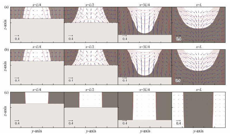
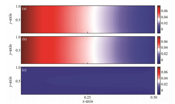
We now examine the contributions of different components of the tidal body force to uL and ζE. First, Fig.5 and Fig.6 respectively compare the contributions of π1 and π2 with f = 0 (i.e., without considering the earth's rotation) in Eqs. (7), (8), (11) and (12). As can be seen, π1 makes much more contribution than π2 for both uL and ζE. Although the topography of the bay in this study is different from that of Cui et al. (2019), the relative contributions of π1 and π2 are similar.
|
Fig. 5 The non-dimensional uL at four cross-sections due to (a) π1 + π2, (b) π1, and (c) π2 in a bay with length equal to 0.5 wavelength for the case of f = 0. The light shaded area represents the bottom topography. The x-direction velocity is toward the bay mouth in the dark shaded area and toward the bay head in the white area. The contour lines denote the magnitude of the x-direction uL with the contour interval of 0.1. The blue arrows represent the velocity in the y-z plane. |
|
Fig. 6 The residual water elevation due to (a) π1 + π2, (b) π1, and (c) π2 for the case of f = 0. |
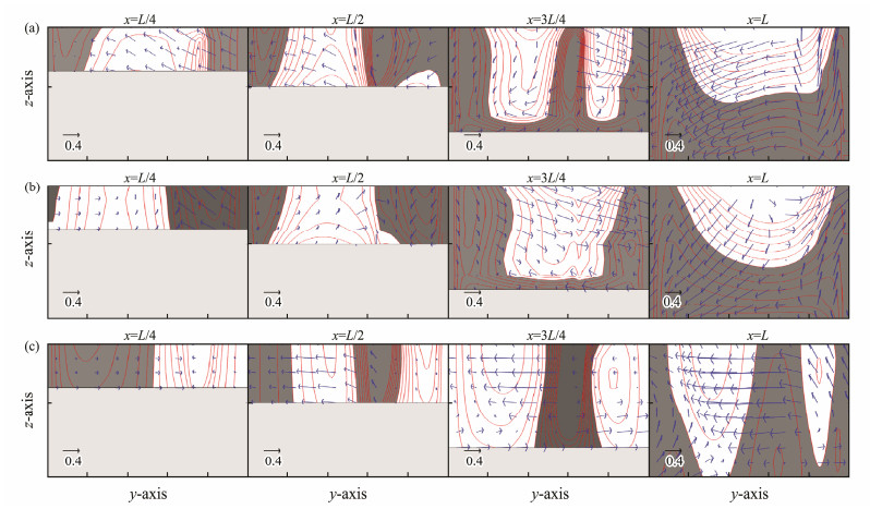
Next, we consider the solution with the Coriolis force not being zero. In this case, Fig.7 shows the distributions of uL due to π, π1 + π2, and π3. Note that the solution for π1 + π2 (Fig.7b) differs from that shown in Fig.5a. Set f ≠ 0 in the left hand side of Eqs. (7) and (8) induces asymmetry in the distribution of uL relative to the center of the bay, in contrast to the case of f = 0. This contribution of the Coriolis force term to uL is similar to that in Cui et al. (2019). Overall, π3 makes a similar important contribution to uL as π1.
|
Fig. 7 Same as in Fig. 5 but for non-dimensional uL due to (a) π, (b) π1 + π2, and (c) π3 for the case of f ≠ 0. |
The geometry of the bay is characterized by two nondimensional numbers, δ = B/λc (bay width to tidal wavelength) and L = L*/λc (bay length to tidal wavelength).
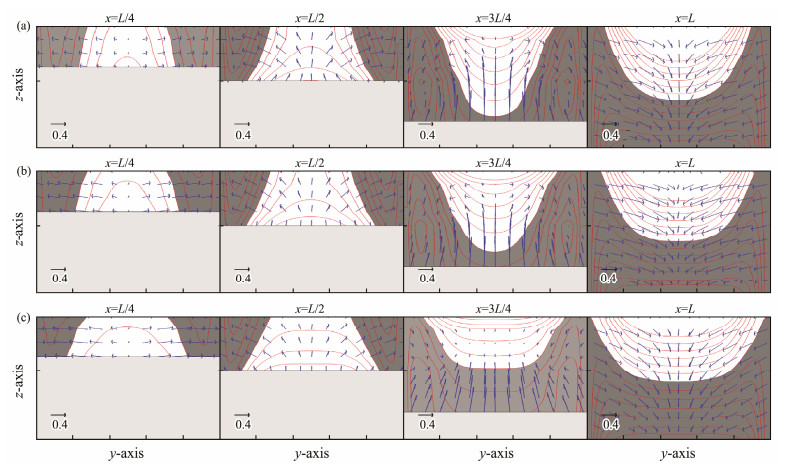
Fig.8 compares uL with different values of δ. Overall, the distribution and intensity of uL do not change significantly for these three cases with δ > 0.1. With increasing δ, the intensity of uL is slightly reduced, and the width of the inflow extends in the bay. Moreover, the depth of inflow becomes shallower in the outer half of the bay.
|
Fig. 8 Same as in Fig. 7 expect for the width-to-wavelength ratios of (a) δ = 0.15, (b) δ = 0.3, and (c) δ = 0.6. |
The similarities in uL for different values of δ can be attributed to the unchanged topographic gradient. Cui et al. (2019) showed that uL is intensified significantly if the topographic gradient increases with different δ values. Without changing the topographic gradient, the different values of δ associated with changes in bay width only cause slight changes in uL.
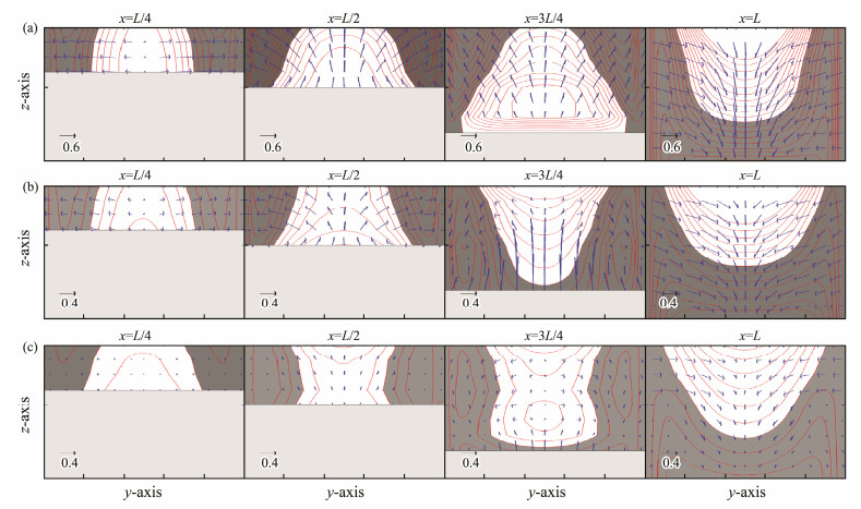
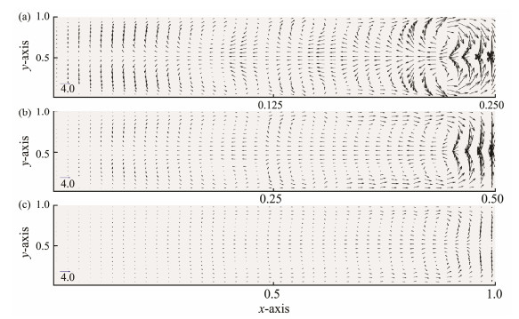
Fig.9 compares uL with three values of L: 0.25, 0.5, and 1. The corresponding depth-integrated uL is displayed in Fig.10. At x = L/4 near the bay head, uL is similar for different values of L. The differences become more significant at the other three sections. Meanwhile, uL becomes weaker as L increases. Three pairs of gyres appear for L = 0.25 and L = 0.5. The two pairs of gyres merge into one for L = 1.
|
Fig. 9 Same as in Fig. 7 expect for the bay lengths of (a) L = 0.25, (b) L = 0.5, and (c) L = 1. |
|
Fig. 10 The depth-integrated uL for bay lengths of (a) L = 0.25, (b) L = 0.5, and (c) L = 1, corresponding to Fig. 9. |
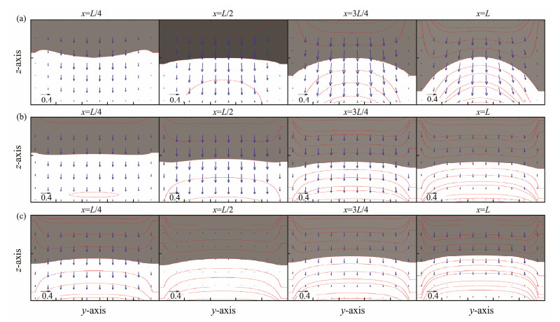
With the presence of topography, the decreasing bay length results in the topographic uplift and the enhancement of the average incoming energy. Fig.11 shows uL with different values of L, but with the topography set to be flat with a depth of 10 m. In this case, uL decreases slightly with increasing L. This suggests that topography is more important than bay length on influencing uL.
|
Fig. 11 Same as in Fig. 9 expect for the uniform water depth. |
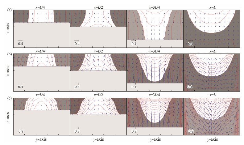
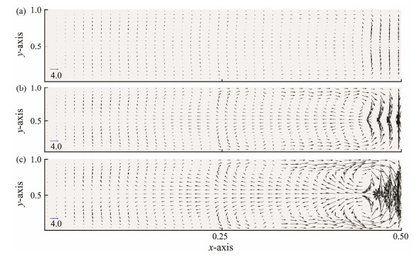
Fig.12 and Fig.13 display uL for different tidal amplitudes (ζopen) at the bay mouth: 50 cm, 100 cm, and 150 cm, respectively. As can be clearly seen, the magnitude of uL increases with increasing ζopen. With ζopen increasing from 50 cm to 150 cm, the maximum of |uL| increases by about nine times at the bay mouth and about three times at x = L/4. For the case of the depth-integrated uL, three pairs of gyres can be found in the bay with ζopen = 50 cm or 100 cm, and the two pairs of gyres near the bay head disappear with ζopen = 150 cm. Furthermore, the region occupied by the inflow becomes larger with the increase of ζopen.
|
Fig. 12 Same as in Fig. 9 expect for (a) ζopen = 50 cm, (b) ζopen = 100 cm, and (c) ζopen = 150 cm. |
|
Fig. 13 Same as in Fig. 10 expect for the different tidal amplitudes at the open boundary (a) ζopen = 50 cm, (b) ζopen = 100 cm, and (c) ζopen = 150 cm, corresponding to Fig. 12. |
The zeroth-order tidal velocity changes linearly with the tidal amplitude at the open boundary without considering the bottom friction dissipation. The tidal body force results from the nonlinear coupling of the zeroth-order tide. With ζopen increased by three times from ζopen = 50 cm to ζopen = 150 cm, the magnitudes of the tidal body force and uL should also increase by nine times. As the bottom friction also increases with the increasing tidal velocity, the magnitude of uL increases by less than nine times. Furthermore, the intensification of uL magnitude becomes lesser from the bay mouth to bay head due to the relative influence of bottom friction increasing toward the bay head.
4.4 Influence of the Momentum Dissipation on uLMomentum dissipation consists of two parts. The first part is the eddy viscosity, related mainly to the vertical eddy viscosity, and the second part is related to the bottom friction. The two parts are coupled together.
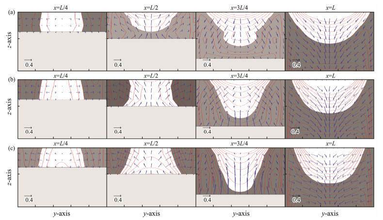
The vertical eddy viscosity coefficient affects uL indirectly from changing the zeroth-order tide, but also directly by changing the intensity of the tidal body force and the vertical momentum transfer in the governing equations of uL. Fig.14 shows uL obtained using three values of the vertical eddy viscosity (υ): 0.002 m2 s−1, 0.004 m2 s−1, and 0.006 m2 s−1. Both the magnitudes and patterns of uL are changed with different values of υ. The magnitude of uL increases by less than two times as υ increases from 0.002 m2 s−1 to 0.006 m2 s−1. With the increasing υ, } the magnitude of π1 increases. At the same time, the vertical transfer of uL also increases. This results in smaller increases in the magnitude of uL relative to the increase in υ. As υ decreases, the vertical transfer of uL also gets smaller. This can explain the subtle differences in the vertical distribution of uL shown in Fig.14.
|
Fig. 14 Same as in Fig. 9 expect for different vertical eddy viscosity coefficients (a) υ = 0.002 m2 s−1, (b) υ = 0.004 m2 s−1, and (c) υ = 0.006 m2 s−1. |
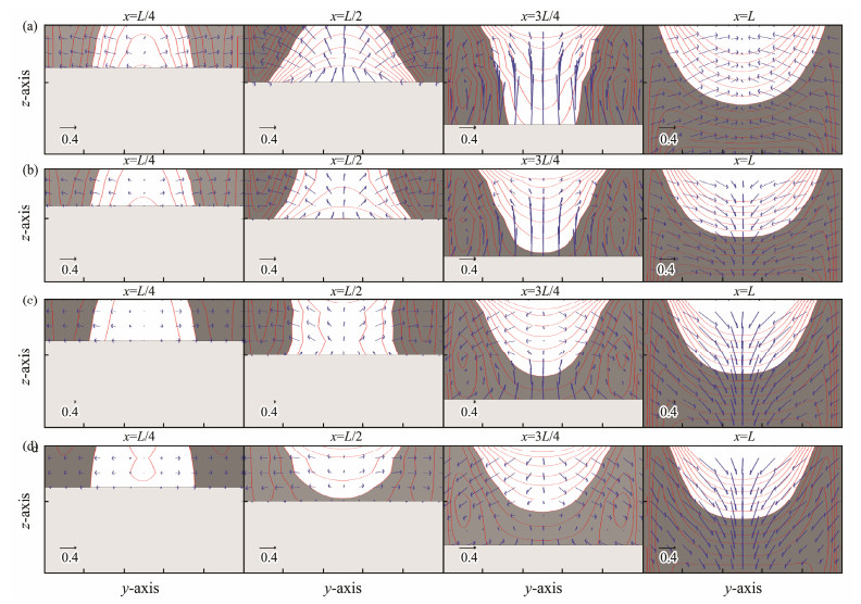
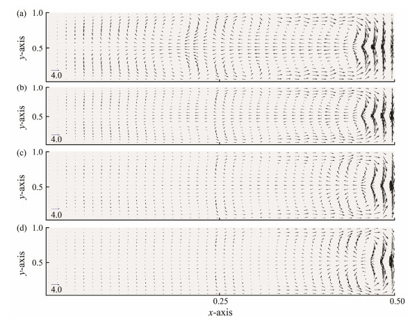
Fig.15 and Fig.16 present the distributions of uL obtained using four values of quadratic bottom friction coefficient, i.e., Cd = 0.00125, 0.0025, 0.005, and 0.01. As the value of Cd increases, the magnitude of uL decreases and the flow pattern becomes simpler. The changes are significant in the inner half than in the outer half of the bay. The changes are minimal near the bay mouth and manifold in inner zone of the bay. With Cd increasing from 0.00125 to 0.01, the maximum value of uL decreases by 30% at x = 3L/4 and by 60% at x = L/4. Obvious changes in the patterns of uL with different values of Cd can also be observed. In particular, with the increasing Cd, the near bottom inflow extends further into the interior of the bay.
|
Fig. 15 Same as in Fig. 9 expect for different bottom friction coefficients (a) Cd = 0.00125}, (b) Cd = 0.0025}, (c) Cd = 0.005}, and (d) Cd = 0.01. |
|
Fig. 16 Same as in Fig. 10 expect for different bottom friction coefficients (a) Cd = 0.00125, (b) Cd = 0.0025, (c) Cd = 0.005, and (d) Cd = 0.01, corresponding to Fig. 15. |
In this study, an improved computing method for the tidal body force is established to obtain a more accurate 3D Lagrangian residual current uL. First, the solution of uL obtained with the new method for an elongated rectangular bay shows better agreement with the analytic solution of Jiang and Feng (2014) and is more accurate than the results of Cui et al. (2019) using the tidalaveraging method. Next, the new method is applied to a wide bay with longitudinal topography. The impacts of various geometrical and physical parameters on the solution of uL are then analyzed.
For the case of the tidal body force without including the Coriolis effect, it is clear that the intensity and pattern of uL are governed by π1, and π2 has a much smaller contribution. This is because π2 is one order of magnitude smaller than π1. The rotation of the earth has two effects: the rotation effect within the residual current equations itself, and the rotation effect in π3 transferred from the zeroth-order tide. The former one creates asymmetry of uL along the center line of the bay. The latter one has the same order of magnitude as π1. Therefore, π3 and π1 jointly determine the solution of uL.
Different geometrical parameters of the bay have varying impacts on uL. The changes of δ (i.e., ratio of bay width to tidal wavelength) do not change the topographic gradient of the bay. Therefore, the solution of uL are similar for different values of δ. The uplift of the longitudinal topography with the decrease of L (ratio of bay length to tidal wavelength) leads to an increase of uL and different circulation patterns. The enhancement of the residual ve locity can be attributed to the larger topographic uplift. Hence, topographic uplift has significant impacts on the Lagrangian residual current.
The incoming tidal strength can significantly affect the intensity of uL. The magnitude of uL increases nearly as much as nine times at the bay mouth and only three times at the bay head when the incoming tidal strength increases by three times. These results are attributed to the quadratic increase of the tidal body force and the enhancement of the bottom friction dissipation.
Two kinds of the dissipation effect in the bay affect uL by different mechanisms. The intensity of the tidal body force rises by about three times when the vertical eddy viscosity coefficient υ also increases by three times, and the intensity of uL increases by less than two times. The dissipation effect of the bottom friction and the eddy viscosity are enhanced correspondingly as the tidal body force rises by three times. This results in less increase of uL than that of the tidal body force.
The intensity of uL reduces with the increase of the bottom friction. The decrease of uL with Cd increasing from 0.00125 to 0.01 is more signified near the bay mouth than near the bay head. This is because the nonlinear effect of the bottom friction dissipation enhances from the bay mouth toward head. The enhancement of the nonlinear bottom friction dissipation inhibits the seawater from flowing into the bay, delays the inflow area reaching the bottom, and finally simplifies the flow state of uL.
AcknowledgementsThis study was supported by the National Natural Science Foundation of China (No. 41676003) and the NSFC Shandong Joint Fund for Marine Science Research Centers (No. U1606402).
Abbott, M. R., 1960. Boundary layer effects in estuaries. Journal of Marine Research, 18: 83-100. (  0) 0) |
Backhaus, J. O., 1985. A three-dimensional model for the simulation of shelf sea dynamics. Deutsche Hydrografische Zeitschrift, 38: 165-187. DOI:10.1007/BF02328975 (  0) 0) |
Cheng, R. T. and Casulli, V., 1982. On Lagrangian residual currents with applications in South San Francisco Bay. Water Resources Research, 18: 1652-1662. DOI:10.1029/WR018i006p01652 (  0) 0) |
Cui, Y. X., Jiang, W. S. and Deng, F. J., 2019. 3D numerical computation of the tidally induced Lagrangian residual current in an idealized bay. Ocean Dynamics, 69(3): 283-300. DOI:10.1007/s10236-018-01243-1 (  0) 0) |
Deng, F. J., Jiang, W. S. and Feng, S. Z., 2017. The nonlinear effects of the eddy viscosity and the bottom friction on the Lagrangian residual velocity in a narrow model bay. Ocean Dynamics, 67: 1105-1118. DOI:10.1007/s10236-017-1076-x (  0) 0) |
Deng, F. J., Jiang, W. S., Valle-Levinson, A. and Feng, S. Z., 2019. 3D modal solution for tidally induced Lagrangian residual velocity with variations in eddy viscosity and bathymetry in a narrow model bay. Journal of Ocean University of China, 18(1): 69-79. DOI:10.1007/s11802-019-3773-1 (  0) 0) |
Feng, S. Z., 1987. A three dimensional weakly nonlinear model of tide-induced Lagrangian residual current and mass transport, with an application to the Bohai Sea. In: Three Dimensional Models of Marine and Estuarine Dynamics. Elsevier Oceanography Series, 45: 471-488. DOI:10.1016/S0422-9894(08)70463-X (  0) 0) |
Feng, S. Z., Ju, L. and Jiang, W. S., 2008. A Lagrangian mean theory on coastal sea circulation with inter-tidal transports Ⅰ: Fundamentals. Acta Oceanologica Sinica, 27: 1-16. (  0) 0) |
Ianniello, J. P., 1977. Tidally induced residual currents in estuaries of constant breadth and depth. Journal of Marine Systems, 35: 755-786. (  0) 0) |
Ianniello, J. P., 1979. Tidally induced residual currents in estuaries of variable breadth and depth. Journal of Physical Oceanography, 9: 962-974. DOI:10.1175/1520-0485(1979)009<0962:TIRCIE>2.0.CO;2 (  0) 0) |
Jiang, W. S. and Feng, S. Z., 2011. Analytical solution for the tidally induced Lagrangian residual current in a narrow bay. Ocean Dynamics, 61: 543-558. DOI:10.1007/s10236-011-0381-z (  0) 0) |
Jiang, W. S. and Feng, S. Z., 2014. 3D analytical solution to the tidally induced Lagrangian residual current equations in a narrow bay. Ocean Dynamics, 64(8): 1073-1091. DOI:10.1007/s10236-014-0738-1 (  0) 0) |
Lei, K., Sun, W. X. and Liu, G. M., 2004. Numerical study of the circulation in the Yellow Sea and East China Sea Ⅳ: Diagnostic calculation of the baroclinic circulation. Journal of Ocean University of China, 34(6): 937-941. (  0) 0) |
Liang, S. X., Han, S. L., Sun, Z. C. and Hu, Z. M., 2014. Lagrangian methods for water transport processes in a long-narrow bay 'C Xiangshan Bay. Journal of Hydrodynamics Series B, 26(4): 558-567. DOI:10.1016/S1001-6058(14)60063-9 (  0) 0) |
Liu, G. L., Liu, Z., Gao, H. W., Gao, Z. X. and Feng, S. Z., 2012. Simulation of the Lagrangian tide-induced residual velocity in a tide-dominated coastal system: A case study of Jiaozhou Bay, China. Ocean Dynamics, 62: 1443-1456. DOI:10.1007/s10236-012-0577-x (  0) 0) |
Liu, G. M., Sun, W. X., Lei, K. and Jiang, W. S., 2002. A numerical study of circulation in the Huanghai Sea and East China Sea '�U: Numerical simulation of barotropic circulation. Journal of Ocean University of China, 32(1): 1-8. (  0) 0) |
Longuet-Higgins, M. S., 1969. On the transport of mass by timevarying ocean currents. Deep-Sea Research, 16: 431-447. (  0) 0) |
Muller, H., Blanke, B., Dumas, F., Lekien, F. and Mariette, V., 2009. Estimating the Lagrangian residual circulation in the Iroise Sea. Journal of Marine Systems, 78: S17-S36. DOI:10.1016/j.jmarsys.2009.01.008 (  0) 0) |
Nihoul, I. C. J. and Ronday, F. C., 1975. The influence of the tidal stress on the residual circulation. Tellus A, 27: 484-489. (  0) 0) |
Pawlowicz, R., Beardsley, B. and Lentz, S., 2002. Classical tidal harmonic analysis including error estimates in MATLAB using T_TIDE. Computers and Geosciences, 28(8): 929-937. DOI:10.1016/S0098-3004(02)00013-4 (  0) 0) |
Pohlmann, T., 1996. Predicting the thermocline in a circulation model of the North Sea part Ⅰ: Model description, calibration and verification. Continental Shelf Research, 16(2): 131-146. DOI:10.1016/0278-4343(95)90885-S (  0) 0) |
Pohlmann, T., 2006. A meso-scale model of the central and southern North Sea: Consequences of an improved resolution. Continental Shelf Research, 26(19): 2367-2385. DOI:10.1016/j.csr.2006.06.011 (  0) 0) |
Quan, Q., Mao, X. Y. and Jiang, W. S., 2014. Numerical computation of the tidally induced Lagrangian residual current in a model bay. Ocean Dynamics, 64: 471-486. DOI:10.1007/s10236-014-0696-7 (  0) 0) |
Sun, W. X., Liu, G. M., Jiang, W. S., Wang, H. and Zhang, P., 2000. The numerical study of circulation in the Yellow Sea and East China Sea Ⅰ. The numerical circulation model in the Yellow Sea and East China Sea. Journal of Ocean University of Qingdao, 30(3): 369-375. (  0) 0) |
Sun, W. X., Liu, G. M., Lei, K., Jiang, W. S. and Zhang, P., 2001. A numerical study on circulation in the Yellow and East China Sea Ⅱ. Numerical simulation of tide and tide-induced circulation. Journal of Ocean University of Qingdao, 31(3): 297-304. (  0) 0) |
Wang, H., Shu, Z. Q., Feng, S. Z. and Sun, W. X., 1993. A threedemensional numerical calculation of the wind-driven thermohaline and tide-induced Lagrangian residual current in the Bohai Sea. Acta Oceanologica Sinica, 12(2): 169-182. (  0) 0) |
Wang, J. X., Gao, H. W., Lei, K. and Sun, W. X., 2006. Numerical study of the circulations in the Yellow Sea and East China Sea Ⅴ: Dynamic adjustment of the baroclinic circulation. Periodical of Ocean University of China, 36(Sup. II): 1-6. (  0) 0) |
Winant, C. D., 2008. Three-dimensional residual tidal circulation in an elongated, rotating basin. Journal of Physical Oceanography, 38: 1278-1295. DOI:10.1175/2007JPO3819.1 (  0) 0) |
Xu, P., Mao, X. Y. and Jiang, W. S., 2016. Mapping tidal residual circulations in the outer Xiangshan Bay using a numerical model. Journal of Marine Systems, 154: 181-191. DOI:10.1016/j.jmarsys.2015.10.002 (  0) 0) |
Zimmerman, J. T. F., 1979. On the Euler-Lagrange transformation and the Stokes' drift in the presence of oscillatory and residual currents. Deep-Sea Research, 26(26A): 505-520. (  0) 0) |
 2019, Vol. 18


