2. 油气藏地质及开发工程国家重点实验室·西南石油大学, 四川 成都 610500
2. State Key Laboratory of Oil and Gas Reservoir Geology and Exploitation, Southwest Petroleum University, Chengdu, Sichuan 610500, China
随着对油气资源需求力度增大,油气勘探开发由常规储层逐渐走向了复杂储层[1-3],从而产生了大量的复杂井型,例如斜井、大斜度井、水平井以满足勘探开发的需求[4-6]。水平井下套管作业中,套管在井眼轨迹和外力作用下会发生弯曲变形[7-10]。套管受井眼约束限制,套管与井壁会发生接触,且接触位置具有不确定性[11]。当套管与井壁接触后,套管的摩阻增大,加大了套管下入难度[12-16]。国内学者对下套管过程中摩阻的研究主要集中在扶正器对摩阻的影响[17-20]。然而,对于下套管过程中套管与井壁的接触性问题,国内外很少对其有详细的分析。针对这一问题,基于对套管弯曲变形研究的现状和特点,通过建立套管与井壁接触方式判断模型,套管与井壁的接触位置计算模型,对套管在井内的挠曲变形和变形后与井壁的接触产生的摩擦阻力问题进行了研究。
1 套管与井壁接触方式套管在井筒移动过程中会随着井眼轨迹的变化而发生完全变形,但由于受井壁约束,会与井壁发生接触。接触位置具有不确定性,接触方式包括两种:(1)点接触:套管与井壁之间发生点接触是因为扶正器与井壁的接触为点接触,如图 1a;(2)线接触:套管柱上的某段与井壁接触,如图 1b。套管在弯曲变形时,由于其径向变形极小,所以,笔者在分析套管与井壁接触方式时,忽略径向变形,只考虑弯曲变形的影响。
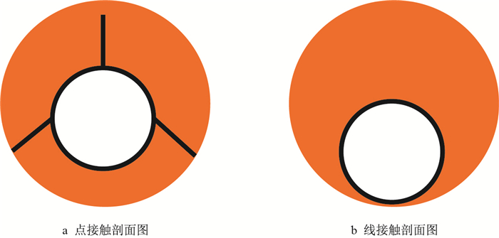 |
| 图1 套管与井壁接触方式 Fig. 1 Contact type between casing and borehole wall |
套管与井壁的接触方式不同,导致套管与井壁间的摩阻系数不同,而摩阻系数又是影响摩擦阻力的主要因素。因此,通过自制的水平井下套管模拟实验装置,模拟测试套管在水基钻井液和油基钻井液中,不同接触方式下的滑动摩阻系数,其测试结果见表 1。
| 表1 不同扶正器和接触方式对摩阻系数的影响 Tab. 1 Effect of different centralizers and contact methods on friction coefficient |
从表 1可以看出,下套管摩阻系数受扶正器类型的较大影响,扶正器类型对摩阻系数大小的影响为:弹性扶正器>刚性扶正器>滚珠型扶正器。无论是在水基钻井液还是在油基钻井液中,弹性扶正器的摩阻系数是滚珠扶正器的3倍以上。如果套管上无扶正器,套管与井壁接触方式为线性接触。套管无扶正器时比刚性扶正器的摩阻小,这是因为无扶正器时,套管处于理想状态,套管压力成均匀线性分布,测得的摩阻系数较小。实际井眼属于不规则通道,同时还存在套管接头的影响,所以,无扶正器时摩阻应大于测量值,应与有刚性扶正器时的摩阻相差不大。这能很好地解释套管存在刚性扶正器时对摩阻影响不太大。
3 套管与井壁接触方式判断 3.1 套管弯曲变形分析根据套管在井眼中的受力情况,将两个扶正器间套管的弯曲挠度用纵横弯曲连续梁模型来分析。为了方便建立套管受力和变形模型,作如下假设[21]:(1)两扶正器间套管为连续光滑曲线;(2)套管发生弹性变形;(3)井壁不可压缩,井眼半径不随时间改变;(4)套管为均质弹性体;(5)扶正器为弹性铰支点。
3.1.1 当轴向载荷为压力时(1) 横向均载荷下套管变形
图 2为单跨度纵横弯曲套管力学模型,取$A$点左端进行受力分析,根据力矩平衡方程,可得套管挠度方程
| $ E_{\rm{I}}y'' = - \dfrac{{qL}}{{\rm{2}}}x + \dfrac{q}{{\rm{2}}}{x^2} - Ty $ | (1) |
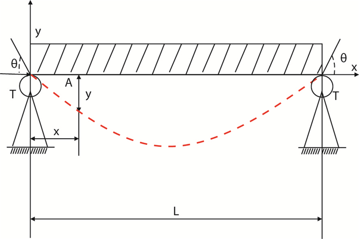 |
| 图2 单跨纵横弯曲梁力学模型 Fig. 2 Mechanical model of single -span bending beam |
式中:
EI-套管柱刚度,N·m2;
y-套管挠度,m;
q-套管重力产生的载荷,N;
L-两扶正器间套管长度,m;
x-观察点距离扶正器的长度,m;
T-套管轴向载荷,N。
令
| $ {y_{\rm max }} = y\left| {_{x = \frac{L}{2}}} \right. = \dfrac{{5q{L^4}}}{{384E_{\rm{I}}}}{\rm{ }}\dfrac{{{\rm{24}} \left( {\sec μ - 1 - \dfrac{1}{2}{μ ^{\rm{2}}}} \right)}} {{{\rm{5}}{μ ^{\rm{4}}}}} $ | (2) |
(2) 端部存在力偶时套管变形
当套管端部有力偶作用时(图 3),力偶导致的套管变形好比在套上作用了MB。这时可以得到,力偶和轴向载荷共同作用下套管的最大挠度
| $ {y_{\rm max }}\left| {_{x = \frac{L}{2}}} \right.{\rm{ = }} \dfrac{{{M_{\rm{B}}}{L^2}}}{{4E_{\rm{I}}{μ ^2}}} \left( {\dfrac{{\sin μ }}{{\sin 2μ }} - \dfrac{{\rm{1}}}{{\rm{2}}}} \right) $ | (3) |
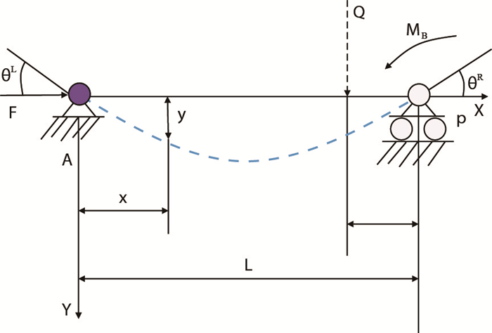 |
| 图3 端部力偶作用下套管挠度曲线 Fig. 3 Deflection curve of casing under end force couple |
式中:
MB-端部受力产生的力偶,N·m,MB= Qc;
Q-作用在端部B的力,N;
c-距离端部B的距离,m。
(3) 套管存在初始弯曲
如果套管已经发生了弯曲变形,此时初始弯曲将对套管的挠度产生影响,初弯曲引起的附加挠度为
| $ {y'_{\rm max }} = \dfrac{{8bE_{\rm{I}}}}{{T{L^2}}} \left( {\dfrac{{\rm{1}}}{{\cos μ }}{\rm{ - 1}}} \right) $ | (4) |
式中:
b-初始弯曲产生的位移,m。
根据叠加原理,套管柱总变形由每个载荷分别与轴向载荷共同作用产生的变形组成,则套管中点的最大挠度值为
| $ {y_{\rm max }} = \dfrac{{q{L^{\rm{4}}}\sin α }} {{{\rm{16}}E_{\rm{I}}{μ ^{\rm{4}}}}}\left( {\dfrac{{\rm{1}}} {{\cos μ }}{\rm{ - 1 - }}\dfrac{{{μ ^{\rm{2}}}}}{{\rm{2}}}} \right){\rm{ + }}\dfrac{{{M_i} + {M_{i + 1}}}}{T} \left( {\dfrac{{\sin μ }}{{\sin 2μ }}{\rm{ - }} \dfrac{{\rm{1}}}{{\rm{2}}}} \right){\rm{ + }}\dfrac{{{L^2}}} {{4R{μ ^2}}}\left( {\dfrac{{\rm{1}}}{{\cos μ }}{\rm{ - 1}}} \right) $ | (5) |
式中:
α-井斜角,(°);
Mi-第i段套管产生的力偶,N·m;
Mi+1-第i+1段套管产生的力偶,N·m;
R-套管弯曲产生的曲率半径,m。
3.1.2 套管轴向载荷为拉力(1) 横向均布载荷作用下变形
当轴向载荷为拉力时,套管挠度求解与当轴向力为压力时相同,套管中点的最大挠度为
| $ {y_{\rm max }} = \dfrac{{5q{L^4}}}{{384E_{\rm{I}}}}{\rm{ × }}\dfrac{{{\rm{12}}}}{{\rm{5}}}\left[ {\dfrac{{{{\rm{μ }}^{\rm{2}}}{\rm{ + }}{μ ^{\rm{2}}}{{\rm{e}}^{{\rm{2μ }}}}{\rm{ - 2}}{{\rm{e}}^{{\rm{2μ }}}}{\rm{ + 4}}{{\rm{e}}^{\rm{μ }}}{\rm{ - 2}}}}{{{μ ^{\rm{4}}}\left( {{{\rm{e}}^{{\rm{2μ }}}}{\rm{ + 1}}} \right)}}} \right] $ | (6) |
(2) 两端有力偶作用
轴向载荷为拉力时套管中点的最大挠度为
| $ {y_{\rm max }} = \dfrac{{{M_{\rm{B}}}{L^2}}}{{16E_{\rm{I}}}} \dfrac{{{\rm{2}}\left( {{\rm{2}}{{\rm{e}}^{\rm{μ }}}{\rm{ - }}{{\rm{e}}^{{\rm{2μ }}}}{\rm{ - 1}}} \right)}}{{{μ ^{\rm{2}}}\left( {{{\rm{e}}^{{\rm{2μ }}}}{\rm{ + 1}}} \right)}} $ | (7) |
(3) 套管存在初始弯曲
如果套管已经发生了弯曲变形,初始弯曲引起的附加挠度为
| $ {y'_{\rm max }} = \dfrac{{ - 8bE_{\rm{I}}}}{{T{L^2}}} \left( {{\rm{1 - }}\dfrac{{\rm{1}}}{{{{\rm{ch~μ}}} }}} \right) $ | (8) |
根据叠加原理,套管柱总变形由每个载荷分别与轴向载荷共同作用产生的变形,则套管中点的最大挠度值为
| $ {y_{\rm max }} = \dfrac{{q{L^4}\sin {{α }} }} {{{\rm{16}}E_{\rm{I}}{μ ^{\rm{4}}}}}\left( {\dfrac{{\rm{1}}} {{{\rm{ch}}~μ }}{\rm{ - 1 + }}\dfrac{{{μ ^{\rm{2}}}}} {{\rm{2}}}} \right){\rm{ + }}\dfrac{{{M_i} + {M_{i + 1}}}}{T} \left( {\dfrac{{\rm{1}}}{{\rm{2}}}{\rm{ - }}\dfrac{{{\rm{sh}}~μ }} {{\sin 2μ }}} \right){\rm{ + }}\dfrac{{{L^2}}}{{4R{μ ^2}}} \left( {{\rm{1 - }}\dfrac{{\rm{1}}}{{{\rm{ch}}~μ }}} \right) $ | (9) |
套管中点最大挠度值为
| $ {y_{\rm max }} = \dfrac{{{\rm{5}}q{L^{\rm{4}}}\sin α }}{{{\rm{384}}E_{\rm{I}}}}{\rm{ + }}\dfrac {{\left( {{M_i} + {M_{i + 1}}} \right){L^2}}}{{16E_{\rm{I}}}} {\rm{ + }}\dfrac{{{L^2}}}{{8R}} $ | (10) |
当套管与井壁接触后,设上端点的井斜角为αi+1,井斜方位角为φi+1;下端点的井斜角为αi,井斜方位角为φi,套管长为Li,其受力分析如图 4所示。
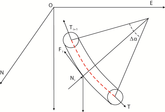 |
| 图4 套管柱的微元段受力 Fig. 4 Stress of microelement section of casing string |
为了更好地分析套管与井壁接触受力分析,作如下假设[13-17]:(1)井眼曲率和直径不随时间变化;(2)不考虑截面剪切应力影响;(3)套管弯曲变形与井眼轴线一致;(4)套管为均质材料。微元段内套管受力包括:自身重力qiLi,井壁对套管的支撑力Ni,摩擦阻力Fi
令
| $ \left\{ \begin{array}{l} {{{\mathit{\boldsymbol{n}}}_1}} = \left( {\sin {\alpha _{{i}}} \cos {{\rm{\varphi }}_{{i}}}, \sin {{\rm{\alpha }}_{{i}}} \sin {{\rm{\varphi }}_{{i}}}, \cos {{\rm{\alpha }}_{{i}}}} \right)\\ {{{\mathit{\boldsymbol{n}}}_2}} = \left( {\sin {{\rm{\alpha }}_{{{i + 1}}}}\cos {{\rm{\varphi }}_{{{i + 1}}}} , \sin {{\rm{\alpha }}_{{{i + 1}}}}\sin {{\rm{\varphi }}_ {{{i + 1}}}}, - \cos {{\rm{\alpha }}_{{{i + 1}}}}} \right)\\ {\mathit{\boldsymbol{k}}} = \left( {{\rm{0, 0, 1}}} \right) \end{array} \right. $ | (11) |
以微元段中心为原点,切线方向为x轴,垂直切线方向为y轴,垂直xoy平面向下为z轴,xoy平面的法向量与重力方向的夹角为θ,则
| $ θ {\rm{ = arccos}}\dfrac{{{\mathit{\boldsymbol{k}}} × \left( { {{{\mathit{\boldsymbol{n}}}_1}} × {{{\mathit{\boldsymbol{n}}}_2}} } \right)}}{{\left| { {{{\mathit{\boldsymbol{n}}}_1}} × {{\mathit{\boldsymbol{n}}_2}} } \right|}} $ | (12) |
两轴向力Ti、Ti+1的夹角为2δ
| $ β {\rm{ = 2δ = arccos}} \left[ {\cos {{\rm{α }}_{{{i + 1}}}}\cos {{\rm{α }}_{{i}}} + \sin {{\rm{α }}_{{{i + 1}}}} \sin {{\rm{α }}_{{i}}}\cos \left( {{{\rm{φ }}_{{{i + 1}}}}{\rm{ - }}{{\rm{φ }}_{{i}}}} \right)} \right] $ | (13) |
式中:
β-轴向力Ti、Ti+1的夹角,(°);
δ-重力分量在xoy平面上的投影与x轴的夹角,(°)。
重力分量在xoy平面上的投影与x轴的夹角σ为
| $ σ {\rm{ = π - arccos}}\dfrac{{{\rm{cos}} {\dfrac{{{{\rm{α }}_{{i}}}{\rm{ + }}{{\rm{α }}_ {{{i + 1}}}}}}{{\rm{2}}}} }}{{{\sin θ }}} $ | (14) |
根据静力学平衡方程和力矩平衡方程可以得到
| $ \left\{ \begin{array}{l} {T_{i + 1}} = \dfrac{{{{{T}}_{{i}}}{\cos δ + } {{{q}}_{{i}}}{{{L}}_{{i}}}\cos {\dfrac{{{{\rm{α }}_ {{{i + 1}}}}{\rm{ + }}{{\rm{α }}_{{i}}}}}{{\rm{2}}}} {\rm{ - }}{{\rm{μ }}_{{i}}}{{{N}}_{{i}}}}}{{{\cos δ }}}\\[11pt] {N_i} = \sqrt {{{\left( {{{{T}}_{{{i + 1}}}}{\sin δ - } {{{T}}_{{i}}}{\sin δ + }{{{q}}_{{i}}}{{{L}}_{{i}}} {\sin θ \sin β }} \right)}^{\rm{2}}}{{ + q}}_{{i}}^{\rm{2}} {{L}}_{{i}}^{\rm{2}}{\rm{co}}{{\rm{s}}^{\rm{2}}}{\rm{θ }}} \end{array} \right. $ | (15) |
式中:
Ti-第i段的轴向载荷,N;
Ti+1-第i+1段的轴向载荷,N;
qi-第i段的单位长度套管的重力,N/m;
Li-第i段的长度,m;
μi-第i段的中间变量,
Ni-第i段井壁对管柱的支撑力,N。
模型求解采用迭代法计算,其步骤如下:(1)设定井底套管轴向力为Ti=0,并设定精度为ε;(2)令Ti + 1 = Ti,计算出Ni,并相应地计算出摩阻力Fi;(3)通过迭代计算出T'i + 1;(4)判断|T'i + 1- Ti + 1|是否满足精度ε要求;若不满足,令Ti + 1 = T'i + 1,继续迭代直到满足精度要求|T'i + 1- Ti + 1| < ε;(5)这时Ti + 1 = T'i + 1,然后计算出Ni和Fi以及Ti + 1。
3.3 套管与井壁接触方式判断模型为了更好地判断套管与井壁的接触方式,假设套管外径或扶正器外径为Dc,井眼直径为Dw,套管与井壁之间的间隙计算方程为
| $ ς {\rm{ = }}\dfrac{{{{{D}}_{\rm{w}}}{\rm{ - }}{{{D}}_{\rm{c}}}}}{{\rm{2}}}{\rm{ - }}{{{y}}_{{\rm{max}}}}{\rm{ - }}{{\rm{δ }}_{\rm{B}}} $ | (16) |
式中:
ς-套管与井壁间的间隙,m;
δB-扶正器受侧向载荷产生的压缩量,m。
把式(5)、式(9)、式(10)代入式(16)中可以得(轴向力T>0为正压力,轴向力T < 0拉力)
| $ ς = \left\{ \begin{array}{l} \dfrac{{{{{D}}_{\rm{w}}}{\rm{ - }}{{{D}}_{\rm{c}}}}}{{\rm{2}}} {\rm{ - }}\dfrac{{{{q}}{{{L}}^{\rm{4}}}\sin {\rm{α }} }} {{{{16E_{\rm{I}}}}{{\rm{μ }}^{\rm{4}}}}}\left( {\dfrac{{\rm{1}}} {{{\cos μ }}}{\rm{ - 1 - }}\dfrac{{{{\rm{μ }}^{\rm{2}}}}} {{\rm{2}}}} \right){\rm{ - }}\dfrac{{{{{M}}_{{i}}}{\rm{ + }}{{{M}}_ {{{i + 1}}}}}}{{{T}}}\left( {\dfrac{{{\sin μ }}}{{{\sin 2μ }}} {\rm{ - }}\dfrac{{\rm{1}}}{{\rm{2}}}} \right){\rm{ - }}\dfrac{{{{{L}}^ {\rm{2}}}}}{{{{4R}}{{\rm{μ }}^{\rm{2}}}}}\left( {\dfrac{{\rm{1}}} {{\cos μ }}{\rm{ - 1}}} \right){\rm{ - }}{{\rm{δ }}_{\rm{B}}},~~~~~{{{T > 0}}} \\ \dfrac{{{{{D}}_{\rm{w}}}{\rm{ - }}{{{D}}_{\rm{c}}}}}{{\rm{2}}} {\rm{ - }}\dfrac{{{{q}}{{{L}}^{\rm{4}}}\sin {\rm{α }} }} {{{{16E_{\rm{I}}}}{{\rm{μ }}^{\rm{4}}}}}\left( {\dfrac{{\rm{1}}} {{{\rm{ch~μ }}}}{\rm{ - 1 + }}\dfrac{{{{\rm{μ }}^{\rm{2}}}}} {{\rm{2}}}} \right){\rm{ - }}\dfrac{{{{{M}}_{{i}}}{\rm{ + }} {{{M}}_{{{i + 1}}}}}}{{{T}}}\left( {\dfrac{{\rm{1}}}{{\rm{2}}} {\rm{ - }}\dfrac{{{\rm{sh~μ }}}}{{{\sin 2μ }}}} \right) {\rm{ - }}\dfrac{{{{{L}}^{\rm{2}}}}}{{{{4R}}{{\rm{μ }}^ {\rm{2}}}}}\left( {{\rm{1 - }}\dfrac{{\rm{1}}}{{{\rm{ch~μ }}}}} \right) {\rm{ - }}{{\rm{δ }}_{\rm{B}}},~~~~~{{{T = 0}}} \\[11pt] \dfrac{{{{{D}}_{\rm{w}}}{\rm{ - }}{{{D}}_{\rm{c}}}}}{{\rm{2}}} {\rm{ - }}\dfrac{{{{q}}{{{L}}^{\rm{4}}}\sin {\rm{α }} }} {{{{16E_{\rm{I}}}}{{\rm{μ }}^{\rm{4}}}}}\left( {\dfrac{{\rm{1}}} {{{\rm{ch~μ }}}}{\rm{ - 1 + }}\dfrac{{{{\rm{μ }}^{\rm{2}}}}} {{\rm{2}}}} \right){\rm{ - }}\dfrac{{{{{M}}_{{i}}}{\rm{ + }} {{{M}}_{{{i + 1}}}}}}{{{T}}}\left( {\dfrac{{\rm{1}}}{{\rm{2}}} {\rm{ - }}\dfrac{{{\rm{sh~μ }}}}{{{\sin 2μ }}}} \right) {\rm{ - }}\dfrac{{{{{L}}^{\rm{2}}}}}{{{{4R}}{{\rm{μ }}^{\rm{2}}}}} \left( {{\rm{1 - }}\dfrac{{\rm{1}}}{{{\rm{ch~μ }}}}} \right){\rm{ - }} {{\rm{δ }}_{\rm{B}}},~~~~~{{{T < 0}}} \end{array} \right. $ | (17) |
如果两扶正器间套管中心处与井壁接触时,将接触点和其中一扶正器视为铰支点进行套管挠度曲线。这时套管受到井壁的正压力作用(如图 5所示),可把正压力看作是作用到套管上的一个集中力,通过叠加方式集中分析其对套管挠度的影响,其套管中点最大挠度为
| $ {{y'}_{\max }} = \left\{ \begin{array}{l} \dfrac{{{{q}}{{{L}}^{\rm{4}}}\sin {\rm{α }} }} {{{{16E_{\rm{I}}}}{{\rm{μ }}^{\rm{4}}}}}\left( {\dfrac{{\rm{1}}} {{{\cos μ }}}{\rm{ - 1 - }}\dfrac{{{{\rm{μ }}^{\rm{2}}}}} {{\rm{2}}}} \right){\rm{ + }}\dfrac{{{{{M}}_{{i}}}{\rm{ + }} {{{M}}_{{{i + 1}}}}}}{{{T}}}\left( {\dfrac{{{\sin μ }}} {{{\sin 2μ }}}{\rm{ - }}\dfrac{{\rm{1}}}{{\rm{2}}}} \right) {\rm{ + }}\dfrac{{{{{L}}^{\rm{2}}}}}{{{{4R}}{{\rm{μ }}^{\rm{2}}}}} \left( {\dfrac{{\rm{1}}}{{{\cos μ }}}{\rm{ - 1}}} \right) {\rm{ - }}\dfrac{{{{NL\tan μ }}}}{{{{\rm{2}}^{{{n + 1}}}} {{μ T}}}}{\rm{ + }}\dfrac{{{{NL}}}}{{{{\rm{2}}^{{{n + 1}}}}{{T}}}},~~~~~{{{T > 0}}} \\[10pt] \dfrac{{5q{{{L}}^{\rm{4}}}\sin {\rm{α }} }} {{{{384E_{\rm{I}}}}}}{\rm{ + }}\dfrac{{\left( {{{{M}}_{{i}}} {\rm{ + }}{{{M}}_{{{i + 1}}}}} \right){{{L}}^{\rm{2}}}}} {{{{16E_{\rm{I}}}}}}{\rm{ + }}\dfrac{{{{{L}}^{\rm{2}}}}}{{{{8R}}}} {\rm{ - }}\dfrac{{{{N}}{{\left( {\dfrac{{{L}}}{{{{\rm{2}}^{{{n - 1}}}}}}} \right)}^{\rm{3}}}}}{{{{96E_{\rm{I}}}}}},~~~~~{{{T = 0}}} \\ \dfrac{{{{q}}{{{L}}^{\rm{4}}}\sin {\rm{α }} }} {{{{16E_{\rm{I}}}}{{\rm{μ }}^{\rm{4}}}}}\left( {\dfrac{{\rm{1}}} {{{\rm{ch~μ }}}}{\rm{ - 1+}}\dfrac{{{{\rm{μ }}^{\rm{2}}}}} {{\rm{2}}}} \right){\rm{ + }}\dfrac{{{{{M}}_{{i}}}{\rm{ + }} {{{M}}_{{{i+ 1}}}}}}{{{T}}}\left( {\dfrac{{\rm{1}}}{{\rm{2}}} {\rm{-}}\dfrac{{{\rm{sh~μ }}}}{{{\sin 2μ }}}} \right) {\rm{+ }}\dfrac{{{{{L}}^{\rm{2}}}}}{{{{4R}}{{\rm{μ }}^{\rm{2}}}}} \left( {{\rm{1 - }}\dfrac{{\rm{1}}}{{{\rm{ch~μ }}}}} \right){\rm{- }}\\ \dfrac{{{{NL}}{{\rm{e}}^{{\rm{3μ }}}}}}{{{{\rm{2}}^{{n}}}{{T}} \left( {{\rm{1-}}{{\rm{e}}^{{\rm{2μ }}}}} \right)}}{\rm{+ }} \dfrac{{{{NL}}{{\rm{e}}^{\rm{μ }}}}}{{{{\rm{2}}^{{n}}}{{T}} \left( {{\rm{1-}}{{\rm{e}}^{{\rm{2μ }}}}} \right)}}{\rm{- }} \dfrac{{{{NL}}}}{{{{\rm{2}}^{{{n + 1}}}}{T}}},~~ {{{T < 0}}} \end{array} \right. $ | (18) |
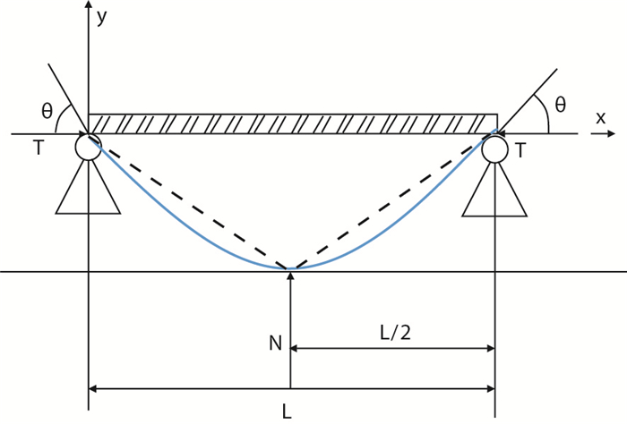 |
| 图5 套管与井壁接触时的挠度曲线 Fig. 5 Deflection curve when the casing contacts the well wall |
这种情况下,套管与井壁间的间隙计算方式与式\(16\)不同,因为套管与井壁间的初始间隙在动态变化。根据轴向力的不同状态,可计算套管接触点与其中一扶正器之间的套管段与井壁之间的最小间隙
| $ ς {\rm{ = }}\left\{ \begin{array}{l} \dfrac{{{{{D}}_{\rm{w}}}{\rm{ - }}{{{D}}_{\rm{c}}}}}{{\rm{2}}} \left( {{\rm{1-}}\dfrac{{{{\rm{2}}^{{n}}}}}{{{L}}}{{x\sin α }}} \right){\rm{ - }}{{{{y'}}}_{{\rm{max}}}}{\rm{ - }}{{\rm{δ }}_{\rm{B}}},{{\rm{α > 4}}{{\rm{5}}^{\rm{^º }}}} \\[10pt] \dfrac{{{{{D}}_{\rm{w}}}{\rm{-}}{{{D}}_{\rm{c}}}}}{{\rm{2}}} \left( {{\rm{1 - }}\dfrac{{{{\rm{2}}^{{n}}}}}{{{L}}}{{x\cos α }}} \right){\rm{ - }}{{{{y'}}}_{{\rm{max}}}}{\rm{-}}{{\rm{δ }}_{\rm{B}}},{{\rm{α ≤ 4}}{{\rm{5}}^{\rm{^º }}}} \end{array} \right. $ | (19) |
式中:
n-迭代的次数。
套管与井壁接触判断模型的计算步骤如下:(1)利用式(19)以井底为初始计算点,计算出套管与井壁间的间隙ς;(2)若ς≤0,则套管与井壁接触;若ς>0,则套管与井壁间无接触;(3)当套管与井壁接触时,对套管中心与其中一个扶正器间的套管段研究,再根据式(19)可计算出中点的间隙,直到套管与井壁无接触。
4 实例计算以四川盆地的WY-00FH井为例进行分析,利用前面建立的模型分析下套管过程中的接触点或者接触段。WY-00FH井的井身结构,如表 2所示。该井采用尾管固井,尾管直径139.7 mm,壁厚12.7 mm,扣型为BG-PCT,采用刚性扶正器提高居中度,其安放位置见表 3。
| 表2 WY-00FH井井身结构表 Tab. 2 Well structure table of Well WY-00FH |
| 表3 WY-00FH井扶正器安放位置 Tab. 3 Positioning of centralizer in Well WY-00FH |
按照前面计算方式分析其套管下入后套管与井壁的实际接触情况。图 6为WY-00FH井井眼轨迹示意图,其套管与井壁接触点或接触段位置通过图例标注在了轨迹线上面。
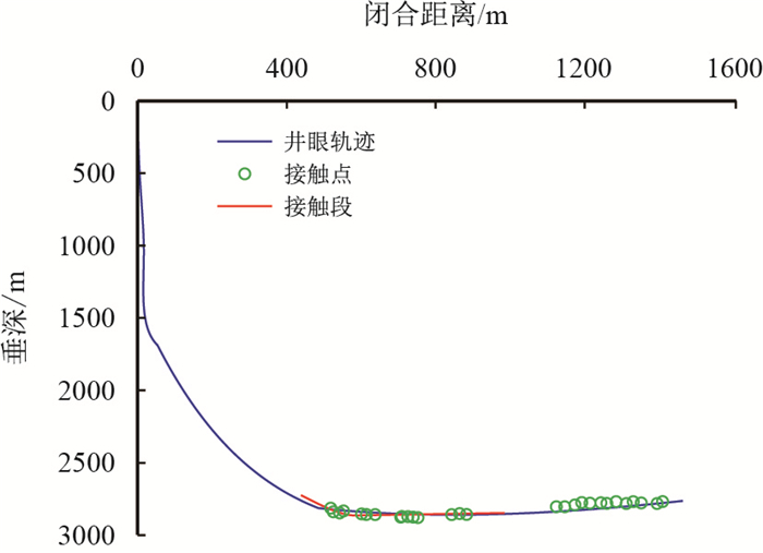 |
| 图6 WY-00FH井套管与井壁接触位置 Fig. 6 The contact position between the casing and the well wall in the Well WY-00FH |
由图 6知,WY-00FH井在2 750.44~4 172.27 m井段,红色部分为套管与井壁间有接触,且为线性接触。图中绿色圆点表示套管与井壁为点接触。通过这些点在井眼轨迹上的位置,可以得到套管与井壁间发生点接触的位置。根据下套管过程中套管与井壁之间的接触情况与受力分析,可计算出下套管过程中套管摩阻和大钩载荷的大小,结果如图 7所示。
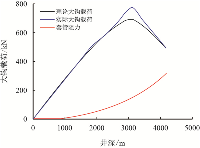 |
| 图7 WY-00FH井的套管下入的摩阻对比曲线 Fig. 7 Contrast curve of frictional resistance of casing running in Well WY-00FH |
从图 7可以看出,套管的摩擦阻力随着井深而逐渐增大,当其下入水平段后套管的摩擦阻力增加最快,并且在这时达到了最大值。大钩载荷随着井深的增加而增加,但是到达3 000 m左右后又随着井深的增加反而减少。通过现场测试数据得出,套管与套管间的摩阻系数为0.25,与裸眼井段摩阻系数为0.30,这表明通过模型计算出的值与实际情况相吻合。
5 结论(1) 加扶正器后套管与井壁之间存在两种接触方式,即线接触和点接触。接触方式与扶正器类型有关,滚珠扶正器产生的摩阻最小。水平井下套管过程中,如果要减小水平段的摩阻,可在水平段尽量选择使用滚珠扶正器或刚性扶正器。
(2) 通过力学分析可以建立起套管与井壁接触方式的判别方法,从而计算出套管与井壁是否接触,当套管与井壁发生接触时,利用迭代法计算出套管与井壁接触段,最后按接触方式分段计算其不同的下入摩阻。
(3) 通过对实例井的接触方式分析与摩阻计算对比,表面套管与井壁接触方式判断模型准确可靠,可以用于准确计算考虑加扶正器后套管的下入摩阻分析。
| [1] |
ZHAO Chaojie, LI Jun, LIU Gonghui, et al. Analysis of the influence of cement sheath failure on sustained casing pressure in shale gas wells[J]. Journal of Natural Gas Science and Engineering, 2019, 66: 244-254. doi: 10.1016/j.jngse.2019.04.003 |
| [2] |
WANG Chaowen, JIA Chunsheng, PENG Xiaolong, et al. Effects of wellbore interference on concurrent gas production from multi-layered tight sands:A case study in eastern Ordos Basin, China[J]. Journal of Petroleum Science and Engineering, 2019, 179: 707-715. doi: 10.1016/j.petrol.2019.04.110 |
| [3] |
CAI Laixing, XIAO Guolin, LU Shuangfang, et al. Spatial-temporal coupling between high-quality source rocks and reservoirs for tight sandstone oil and gas accumulations in the Songliao Basin, China[J]. International Journal of Mining Science and Technology, 2019, 29(3): 387-397. doi: 10.1016/j.ijmst.2019.03.006 |
| [4] |
李勇明, 陈希, 江有适, 等. 页岩储层压裂水平井气水两相产能分析[J]. 油气地质与采收率, 2019, 26(3): 117-122. LI Yongming, CHEN Xi, JIANG Youshi, et al. Gas-water two-phase productivity analysis for the fractured horizontal well in shale reservoirs[J]. Petroleum Geology and Recovery Efficiency, 2019, 26(3): 117-122. doi: 10.13673/j.cnki.cn37-1359/te.2019.03.016 |
| [5] |
NIE Zhen, ZHANG Zhenyou, LUO Huihong, et al. Key technologies for directional well drilling in high-pressure anhydrite salt layers[J]. Natural Gas Industry B, 2018, 5(6): 598-605. doi: 10.1016/j.ngib.2018.11.008 |
| [6] |
GUO Jing, FAN Song, LIU Tao, et al. Exploration and practice of integrated control technology for tubing and sucker rod lopsided wearing in directional well[J]. IOP Conference Series:Earth and Environmental Science, 2018, 208(1): 26-28. doi: 10.1088/1755-1315/208/1/0120-21 |
| [7] |
张珍. ZX105井卡套管事故原因分析及处理工艺[J]. 钻井液与完井液, 2018, 35(3): 84-88. ZHANG Zhen. Analyses of the cause of casing sticking in Well ZX105 and the techniques of freeing the sticking[J]. Drilling Fluid & Completion Fluid, 2018, 35(3): 84-88. doi: 10.3969/j.issn.1001-5620.2018.03.014 |
| [8] |
陈颖超. 基于有限元分析的水平井套管柱下入过程模拟[J]. 承德石油高等专科学校学报, 2019, 21(1): 26-29, 44. CHEN Yingchao. Simulation of casing string down process in horizontal wells based on finite element analysis[J]. Journal of Chengde Petroleum College, 2019, 21(1): 26-29, 44. doi: 10.3969/j.issn.1008-9446.2019.01.008 |
| [9] |
杨广国, 陶谦, 刘伟, 等. 页岩气井固井套管居中与下入能力研究[J]. 石油机械, 2012, 40(10): 26-30. YANG Guangguo, TAO Qian, LIU Wei, et al. Research on the running and centralization of casing in shale gas well[J]. China Petroleum Machinery, 2012, 40(10): 26-30. doi: 10.16082/j.cnki.issn.1001-4578.2012.10.010 |
| [10] |
魏殿举. 川西地区中浅水平井钻井难点与对策[J]. 钻采工艺, 2015, 38(2): 10.107. doi: 10.3969/J.ISSN.1006-768X.2015.02.31 |
| [11] |
王秀文, 刘巨保, 黄金波, 等. 固井过程套管串屈曲变形分析[J]. 石油矿场机械, 2011, 40(4): 17-21. WANG Xiuwen, LIU Jubao, HUANG Jinbo, et al. Analysis of buckling deformation about casing in cementing[J]. Oil Field Equipment, 2011, 40(4): 17-21. doi: 10.3969/j.issn.1001-3482.2011.04.005 |
| [12] |
李子丰. 油气井杆管柱力学研究进展与争论[J]. 石油学报, 2016, 37(4): 531-556. LI Zifeng. Research advances and debates on tubular mechanics in oil and gas wells[J]. Acta Petrolei Sinica, 2016, 37(4): 531-556. doi: 10.7623/syxb201604013 |
| [13] |
牛成成, 郑德帅, 杨顺辉, 等. 大位移井套管下入摩阻预测新方法[J]. 科学技术与工程, 2014, 14(6): 130-134. NIU Chengcheng, ZHENG Deshuai, YANG Shunhui, et al. The new drag prediction method of casing string in extended reach wells[J]. Science Technology and Engineering, 2014, 14(6): 130-134. doi: 10.3969/j.issn.1671-1815.2014.06.029 |
| [14] |
刘晓坡, 廖前华, 李刚. 软件预测摩阻-随钻校正摩阻系数方法及其在BZ34-1-D6大位移井钻井中的应用[J]. 中国海上油气, 2010, 22(5): 320-322, 348. LIU Xiaopo, LIAO Qianhua, LI Gang. The method of friction prediction with software before drilling and friction factor correction while drilling and its application in extended reach Well BZ34-1-D6[J]. China Offshore Oil and Gas, 2010, 22(5): 320-322, 348. doi: 10.3969/j.issn.1673-1506.2010.05.009 |
| [15] |
黄志强. 定向井下套管摩阻数值计算及其应用[J]. 石油地质与工程, 2009, 23(4): 79-81. HUANG Zhiqiang. Computation and application of friction number of casing running in directional well[J]. Petroleum Geology and Engineering, 2009, 23(4): 79-81. doi: 10.3969/j.issn.1673-8217.2009.04.027 |
| [16] |
付建红, 龚龙祥, 胡顺渠, 等. 基于ANSYS的水平井下套管摩阻分析计算[J]. 石油钻采工艺, 2007, 29(4): 32-35. FU Jianhong, GONG Longxiang, HU Shunqu, et al. Calculation of frictional drag of casing running in horizontal well based on ANSYS[J]. Oil Drilling & Production Technology, 2007, 29(4): 32-35. doi: 10.3969/j.issn.1000-7393.2007.04.009 |
| [17] |
王治国, 徐璧华, 陈超, 等. 复杂井眼条件下扶正器对套管下入摩阻的影响研究[J]. 钻采工艺, 2014, 37(1): 27-30. WANG Zhiguo, XU Bihua, CHEN Chao, et al. Centralizer's influences on casing friction under the condition of complicated borehole[J]. Drilling & Production Technology, 2014, 37(1): 27-30. doi: 10.3969/J.ISSN.1006-768X.2014.01.09 |
| [18] |
张海山, 张凯敏, 宫吉泽, 等. 不同类型扶正器对水平井下套管摩阻的影响研究[J]. 钻采工艺, 2014, 37(3): 22-25. ZHANG Haishan, ZHANG Kaimin, GONG Jize, et al. Study on influence of different types of centralizer on running casing friction in horizional well[J]. Drilling & Production Technology, 2014, 37(3): 22-25. doi: 10.3969/J.ISSN.1006-768X.2014.03.07 |
| [19] |
游尧, 陈英明, 姜韡, 等. 考虑扶正器影响的套管摩阻计算方法研究[J]. 长江大学学报(自科版), 2014, 11(1): 71-73. YOU Yao, CHEN Yingming, JIANG Wei, et al. Study on casing friction calculation method considering the effect of centralizer[J]. Journal of Yangtze University (Natural Science Edition), 2014, 11(1): 71-73. |
| [20] |
付建红, 黄贵生, 杨志彬, 等. 水平井套管扶正器合理安放位置计算[J]. 西南石油大学学报(自然科学版), 2008, 30(6): 89-91, 172. FU Jianhong, HUANG Guisheng, YANG Zhibin, et al. Optimal spacing for casing centralizers in horizontal well[J]. Journal of Southwest Petroleum University (Science & Technology Edition), 2008, 30(6): 89-91, 172. doi: 10.3863/j.issn.1000-2634.2008.06.021 |
| [21] |
朱炳坤, 刘江, 窦益华. 造斜井段中套管柱挠曲变形分析[J]. 钻采工艺, 2016, 39(1): 96-98. ZHU Bingkun, LIU Jiang, DOU Yihua. The deflection analysis of casing string in making inclination segment[J]. Drilling & Production Technology, 2016, 39(1): 96-98. doi: 10.3969/J.ISSN.1006-768X.2016.01.28 |
 2020, Vol. 42


