2. 陕西华燕航空仪表有限公司, 陕西 西安 710199;
3. 成都北方石油勘探开发技术有限公司, 四川 成都 610051;
4. 延长油田股份有限公司物资装备部, 陕西 延安 716000
2. Avic Shaanxi Huayan Aero-Instrument Co. Ltd., Xi'an, Shaanxi 710199, China;
3. Chengdu North Petroleum Exploration and Development Technology Company Limited, Chengdu, Sichuan 610051, China;
4. Material and Equipment Department, Yanchang Oilfield Company Limited, Yan'an, Shaanxi 716000, China
微球聚焦测井仪是测井领域一种十分重要的测井设备。微球推靠系统是安装在测井仪上辅助测井仪完成井下测井任务的关键设备[1]。随着石油行业的发展,从早期的直井发展到当下的水平井、大斜井、定向井等众多类型,油井类型日益丰富,井筒复杂程度也越来越高,先前的测井仪器对当下的井况已不完全适应,在实际工程应用中出现了各种各样的问题[2]。例如,像微球推靠系统存在的传动机构复杂,运动可靠性低,在测井作业过程中出现的推靠臂运动到位但推靠力不足,机构无法实现推靠臂的完全张开与收拢动作等问题,因此,需要提出针对性的新型测井仪器来满足油田的实际发展需求。
测井仪器工作在数千米的井下,地处于高温、高压环境,仪器被各种腐蚀性介质浸泡、并且在仪器测试过程中伴有冲击与振动现象,工况十分恶劣。目前,国外关于测井仪推靠系统方面的理论研究鲜有报道,国内这方面的研究也并不多见,大多是基于工程实践应用的工程性论述文章。例如,杨柏青对单臂推靠器的力学性能进行了探讨分析[3],通过对推靠器进行受力分析,研究了推靠机构各杆件受力与影响该受力因素的理论关系。但受限于当时的技术背景,仅进行了推靠系统的静力分析,未考虑推靠系统运动过程中的动力特性,因此具有较大的局限性。随后,相关学者进行了大量的工程应用开发。王会来等进行了新型测井仪推靠装置的设计和分析[4];纪新福进行了推靠器中多功能连杆机构的设计及应用研究[5];邢家乐等应用ADAMS运动仿真平台,进行了对新型VSP(垂直地震剖面)仪器推靠机构的仿真与优化等[6-7]。赵斌基于MATLAB进行了VSP测井仪推靠机构的优化设计研究[8]。
但由于仪器使用工况环境复杂,考虑成本与实验的真实性,很难进行地面的工程实验来对所建立各种模型进行实验校正。因此,为更好地掌握微球推靠系统的工作状态,应用闭环矢量链法建立推靠系统传动机构的运动学模型[9]。进行运动学求解分析,以此为基础对推靠系统进行动力学分析与仿真。描述推靠系统任意时刻的运动状态并揭示推靠系统各构件的运动与受力关系[10]。
1 微球聚焦测井推靠系统虚拟样机利用Pro/E对推靠系统进行建模,微球聚焦测井仪推靠系统结构模型如图 1所示。
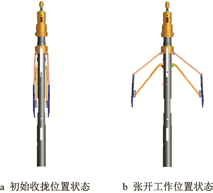 |
| 图1 微球聚焦测井仪推靠系统虚拟样机 Fig. 1 Virtual prototype of push system for microsphere focusing logging instrument |
微球聚焦测井仪推靠系统机械传动组成主要包括:电机、丝杠、传动系统自锁装置、向心球轴承组、丝杠螺母、推力棒、连接杆、推靠上臂、推靠内壁、推靠极板、连接臂、储能弹簧等组成。
2 运动学分析 2.1 建立机构的矢量位置约束方程根据前述运动机理对微球聚焦测井仪推靠系统进行简化,得出其机构运动简图如图 2所示。
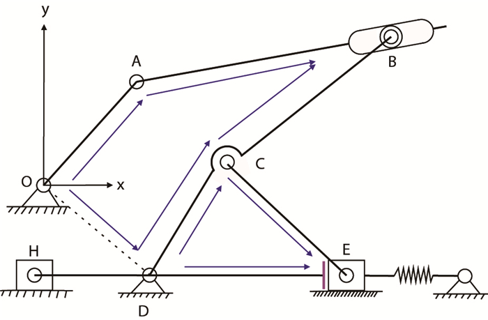 |
| 图2 微球聚焦测井仪推靠系统单臂机构运动简图 Fig. 2 Motion diagram of single arm mechanism of push system with microsphere focusing logging instrument |
在建立机构的矢量位置约束方程时,需将构件用矢量来表示,并作出机构的封闭矢量多边形[11-12]。如图 2所示,以推靠上臂的固定铰接点为坐标原点,建立图示坐标系。机构中推靠上臂
如图 2所示,推靠系统单臂机构在运动时,其传动杆件在平面上构成两个封闭的矢量多边形,即封闭矢量三角形
根据封闭矢量四边形
| $ OA + AB = OD + DC + CB $ | (1) |
| $ {DC} + {CE} = {DE} $ | (2) |
将矢量位置约束方程(1)向坐标方向上投影,即可得如下位移方程组
| $ \left\{ {\begin{array}{*{20}{c}} {x \to }&{{l_1}\cos {\theta _1} + {s_{AB}}\cos {\theta _2} = {x_D} + {l_{DC}}\cos {\theta _4} + {l_{CB}}\cos \gamma }\\ {y \to }&{{l_1}\sin {\theta _1} + {s_{AB}}\sin {\theta _2} = {y_D} + {l_{DC}}\sin {\theta _4} + {l_{CB}}\sin \gamma } \end{array}} \right. $ | (3) |
其中:
式中:
将矢量位置约束方程(2)向坐标方向上投影,即可得如下位移方程组
| $ \left\{ {\begin{array}{*{20}{c}} {x \to }&{{l_{DC}}\cos {\theta _4} + {x_D} + {l_6}\cos {\theta _6} = {x_E}}\\ {y \to }&{{l_{DC}}\sin {\theta _4} + {y_D} + {l_6}\sin {\theta _6} = {y_E}} \end{array}} \right. $ | (4) |
式中:
在三角形
| $ \left\{ {\begin{array}{*{20}{c}} {{\theta _4} = \arccos \left( {\dfrac{{l_{DC}^2 + s_{DE}^2 - l_6^2}}{{2{l_{DC}}{s_{DE}}}}} \right)}\\[11pt] {{\theta _6} = \arccos \left( {\dfrac{{{s_{DE}}^2 + l_6^2 - l_{DC}^2}}{{2{s_{DE}}{l_6}}}} \right)} \end{array}} \right. $ | (5) |
式中:
将式(3)整理变换可得方程组
| $ \left\{ \begin{array}{l} {\Delta _1}\sin {\theta _2} + {\Delta _2}\cos {\theta _2} = 0\\ {\Delta _1} = {x_D} - {x_A} + {l_{DC}}\cos {\theta _4} + {l_{CB}}\cos \gamma \\ {\Delta _2} = - \left( {{y_D} - {y_A} + {l_{DC}}\sin {\theta _4} + {l_{CB}}\sin \gamma } \right) \end{array} \right. $ | (6) |
将式(6)代入到式(3)中求解可得
| $ \left\{ \begin{array}{l} {\theta _2} = 2\arctan \dfrac{{{\Delta _1} - \sqrt {{\Delta _1}^2 + {\Delta _2}^2} }}{{{\Delta _2}}}\\ {s_{AB}} = \dfrac{{{x_D} - {x_A} + {l_{DC}}\cos {\theta _4} + {l_{CB}}\cos \gamma }}{{\cos {\theta _2}}} \end{array} \right. $ | (7) |
根据以上角度求解,可得出推靠系统各杆件机构质心位移方程如下
| $ \left\{ {\begin{array}{l} {{s_1} = \sqrt {{{\left( {{l_{1O}}\cos {\theta _1}} \right)}^2} + {{\left( {{l_{1O}}\sin {\theta _1}} \right)}^2}} }\\ {{s_2} = \sqrt {{{\left( {{l_1}\cos {\theta _1} + {l_{2A}}\cos {\theta _2}} \right)}^2} + {{\left( {{l_1}\sin {\theta _1} + {l_{2A}}\sin {\theta _2}} \right)}^2}} }\\ {{s_B} = \sqrt {{{\left( {{l_1}\cos {\theta _1} + {s_{AB}}\cos {\theta _2}} \right)}^2} + {{\left( {{l_1}\sin {\theta _1} + {s_{AB}}\sin {\theta _2}} \right)}^2}} }\\ {{s_C} = \sqrt {{{\left( {{l_{DC}}\cos {\theta _4} + {x_D}} \right)}^2} + {{\left( {{l_{DC}}\sin {\theta _4} + {y_D}} \right)}^2}} }\\ {{s_6} = \sqrt {{{\left[ {{x_D} + {l_{DC}}\cos {\theta _4} + \left( {{l_6} - {l_{6E}}} \right)\cos {\theta _6}} \right]}^2} + {{\left[ {{y_D} + {l_{DC}}\sin {\theta _4} + \left( {{l_6} - {l_{6E}}} \right)\sin {\theta _6}} \right]}^2}} }\\ {{s_7} = {x_E} - {l_{7H}}}\\ {{s_E} = {x_{E - 0}} + {v_E}t}\\ {{s_H} = {x_H} - {l_7}} \end{array}} \right. $ | (8) |
式中:
通过位移方程式(3)、式(4)对时间
| $ \left[ {\begin{array}{*{20}{c}} {\cos {\theta _2}}&{ - {s_{AB}}\sin {\theta _2}}\\ {\sin {\theta _2}}&{{s_{AB}}\cos {\theta _2}} \end{array}} \right]\left[ {\begin{array}{*{20}{c}} {{{\dot s}_{AB}}}\\ {{\omega _2}} \end{array}} \right] = \left[ {\begin{array}{*{20}{c}} {{l_1}\sin {\theta _1}}&{ - {l_{DC}}\sin {\theta _4} - {l_{CB}}\sin \gamma }\\ {{l_1}\cos {\theta _1}}&{{l_{DC}}\cos {\theta _4} + {l_{CB}}\cos \gamma } \end{array}} \right]\left[ {\begin{array}{*{20}{c}} {{\omega _1}}\\ {{\omega _4}} \end{array}} \right] $ | (9) |
式中:
| $ \left[ {\begin{array}{*{20}{c}} { - {l_{DC}}\sin {\theta _4}}&{ - {l_6}\sin {\theta _6}}\\ {{l_{DC}}\cos {\theta _4}}&{{l_6}\cos {\theta _6}} \end{array}} \right]\left[ {\begin{array}{*{20}{c}} {{\omega _4}}\\ {{\omega _6}} \end{array}} \right] = \left[ {\begin{array}{*{20}{c}} {{v_E}}\\ 0 \end{array}} \right] $ | (10) |
从而解出
| $ \left\{ {\begin{array}{l} {{v_1} = \sqrt {{{\left( { - {l_{1O}}{\omega _1}\sin {\theta _1}} \right)}^2} + {{\left( {{l_{1O}}{\omega _1}\cos {\theta _1}} \right)}^2}} }\\[2pt] {{v_2} = \sqrt {{{\left( { - {l_1}{\omega _1}\sin {\theta _1} - {l_{2A}}{\omega _2}\sin {\theta _2}} \right)}^2} + {{\left( {{l_1}{\omega _1}\cos {\theta _1} + {l_{2A}}{\omega _2}\cos {\theta _2}} \right)}^2}} }\\[2pt] {{v_B} = \sqrt {{{\left( {{{\dot x}_A} + {{\dot s}_{AB}}\cos {\theta _2} - {s_{AB}}{\omega _2}\sin {\theta _2}} \right)}^2} + {{\left( {{{\dot y}_A} + {{\dot s}_{AB}}\sin {\theta _2} + {s_{AB}}{\omega _2}\cos {\theta _2}} \right)}^2}} }\\[2pt] {{v_C} = \sqrt {{{\left( { - {l_{DC}}{\omega _4}\sin {\theta _4}} \right)}^2} + {{\left( {{l_{DC}}{\omega _4}\cos {\theta _4}} \right)}^2}} }\\[2pt] {{v_6} = \sqrt {{{\left[ { - {l_{DC}}{\omega _4}\sin {\theta _4} - \left( {{l_6} - {l_{6E}}} \right){\omega _6}\sin {\theta _6}} \right]}^2} + {{\left[ {{l_{DC}}{\omega _4}\cos {\theta _4} + \left( {{l_6} - {l_{6E}}} \right){\omega _6}\cos {\theta _6}} \right]}^2}} }\\[2pt] {{v _7} = {{\left( {{x_E} - {l_{7H}}} \right)}^\prime } = {v_E}}\\ {{v _E} = {{\left( {{x_{E - 0}} + {v_E}t} \right)}^\prime } = {v_E}}\\ {{v _H} = {{\left( {{x_E} - {l_7}} \right)}^\prime } = {{\dot x}_E} = {v_E}} \end{array}} \right. $ | (11) |
式中:
将速度方程组(9)、(10)对时间取一阶导,得如下加速度、角加速度矩阵方程(12)、(13)
| $ \left[ {\begin{array}{*{20}{c}} {\cos {\theta _2}}&{ - {s_{AB}}\sin {\theta _2}}&{{l_{DC}}\sin {\theta _4} + {l_{CB}}\sin \gamma }\\ {\sin {\theta _2}}&{{s_{AB}}\cos {\theta _2}}&{ - {l_{DC}}\cos {\theta _4} - {l_{CB}}\cos \gamma } \end{array}} \right]\left[ {\begin{array}{*{20}{c}} {{{\ddot s}_{AB}}}\\ {{\alpha _2}}\\ {{\alpha _4}} \end{array}} \right] =\\ \left[ {\begin{array}{*{20}{c}} {{l_1}{\omega _1}\cos {\theta _1}}&{2{{\dot s}_{AB}}\sin {\theta _2} + {s_{AB}}{\omega _2}\cos {\theta _2}}&{ - \left( {{l_{DC}}\cos {\theta _4} + {l_{CB}}\cos \gamma } \right){\omega _4}}\\ {{l_1}{\omega _1}\sin {\theta _1}}&{ - 2{{\dot s}_{AB}}\cos {\theta _2} + {s_{AB}}{\omega _2}\sin {\theta _2}}&{ - \left( {{l_{DC}}\sin {\theta _4} + {l_{CB}}\sin \gamma } \right){\omega _4}} \end{array}} \right]\left[ {\begin{array}{*{20}{c}} {{\omega _1}}\\ {{\omega _2}}\\ {{\omega _4}} \end{array}} \right] $ | (12) |
| $ \left[ {\begin{array}{*{20}{c}} { - {l_{DC}}\sin {\theta _4}}&{ - {l_6}\sin {\theta _6}}\\ {{l_{DC}}\cos {\theta _4}}&{{l_6}\cos {\theta _6}} \end{array}} \right]\left[ {\begin{array}{*{20}{c}} {{\alpha _4}}\\ {{\alpha _6}} \end{array}} \right] = \left[ {\begin{array}{*{20}{c}} {{l_{DC}}{\omega _4}\cos {\theta _4}}&{{l_6}{\omega _6}\cos {\theta _6}}\\ {{l_{DC}}{\omega _4}\sin {\theta _4}}&{{l_6}{\omega _6}\sin {\theta _6}} \end{array}} \right]\left[ {\begin{array}{*{20}{c}} {{\omega _4}}\\ {{\omega _6}} \end{array}} \right] $ | (13) |
式中:
可得以下参量:
| $ \left\{ {\begin{array}{l} {{a_1} = \sqrt {{\varPhi _{1 - 1}} + {\varPhi _{1 - 2}}} }\\ {{a_2} = \sqrt {{\varPhi _{2 - 1}} + {\varPhi _{2 - 2}}} }\\ {{a_B} = \sqrt {{\varPhi _{B - 1}} + {\varPhi _{B - 2}}} }\\ {{a_C} = \sqrt {{\varPhi _{C - 1}} + {\varPhi _{C - 2}}} }\\ {{a_6} = \sqrt {{\varPhi _{6 - 1}} + {\varPhi _{6 - 2}}} }\\ {{a_7} = {{\left( {{x_E} - {l_{7H}}} \right)}^{\prime \prime }} = {{\dot v}_E} = 0}\\ {{a_E} = {{\left( {{x_{E - 0}} + {v_E}t} \right)}^{\prime \prime }} = {{\dot v}_E} = 0}\\ {{a_H} = {{\left( {{x_E} - {l_7}} \right)}^{\prime \prime }} = {{\dot v}_E} = 0} \end{array}} \right. $ | (14) |
式中:
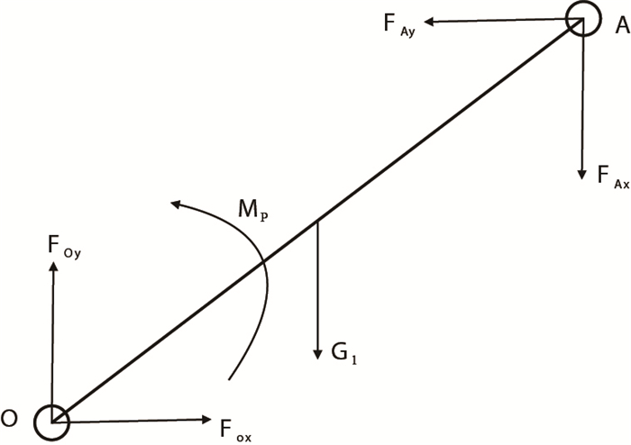
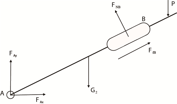
推靠系统各杆件受力情况如图 3
 |
|
图3
推靠上臂 |
 |
|
图4
推靠极板 |
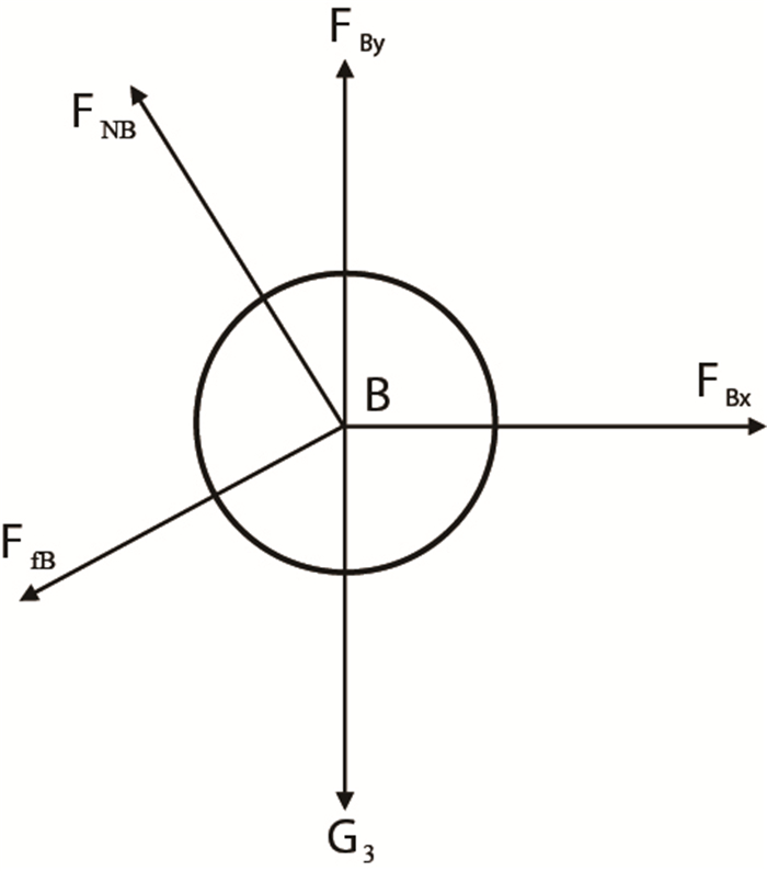 |
|
图5
圆柱销 |
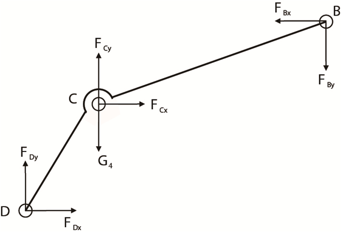 |
|
图6
推靠内臂 |
(1) 取推靠上臂
式中:
(2) 取推靠极板AB为研究对象。
式中:
(3) 取推靠极板滑槽内圆柱销
式中:
(4) 取推靠内臂
式中:
3106微球聚焦测井仪推靠系统中各杆件尺寸参数如下。
链接臂
运用MATLAB,通过数值计算分析[15],可以得出推靠系统中主要部件的运动曲线如图 7,图 8所示。
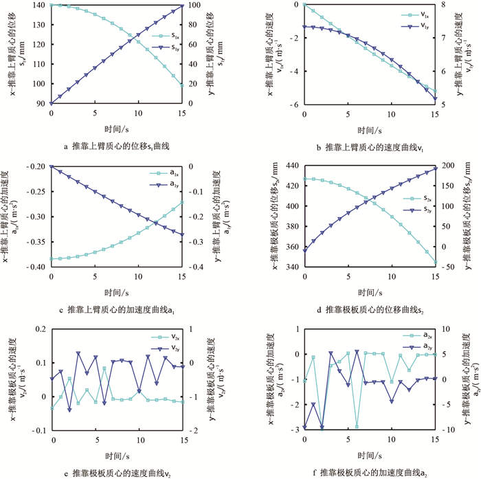 |
| 图7 推靠上臂与推靠极板的运动曲线 Fig. 7 Kinematic curve between push arm and push plate |
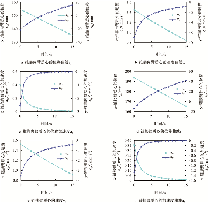 |
| 图8 推靠内臂与链接臂的运动曲线 Fig. 8 Kinematic curve between the inner arm and the link arm |
从图 7可以看出,原动件推靠上臂的质心位移、速度、加速度曲线十分平滑,而推靠极板仅仅只有质心位移能够保持平滑,而其质心速度、加速度则在整个运动过程中会出现持续的跳动。造成该跳动的原因有以下几点:首先,由于在运动分析过程中进行了模型简化,从而给推靠系统的整体运动带来了微小的结构冲击。其次,在推靠极板的运动过程中受到推靠上臂以及丝杠螺母传递过来的运动驱动的同时,还要受到裸眼井井壁的坑洼情况的约束,因此,在推靠系统的整个运动过程中,推靠极板的质心速度,加速度会出现跳动,但保持在较小的范围内,参照工程经验,从整体运动来说其运动规律符合实际的工程运动状态。
5 仿真 5.1 测井仪推靠系统动力学仿真模型在ADAMS中根据相应简化规则,建立微球推靠系统的简化刚体模型;对所建立的推靠系统的刚体模型进行材料属性添加;在添加完材料属性并验证确保无误后,根据各部件间的连接关系对各刚体连接件之间进行相应的约束添加,运动副、驱动加载,从而完成动力学模型的建立[18-19]。图 9为简化微球推靠系统动力学分析模型。
 |
| 图9 微球聚焦测井仪推靠系统动力学分析模型 Fig. 9 Dynamic analysis model of push-system for microsphere focusing logging instrument |
经过虚拟仿真求解,微球推靠系统各杆件机构的运动曲线如图 10
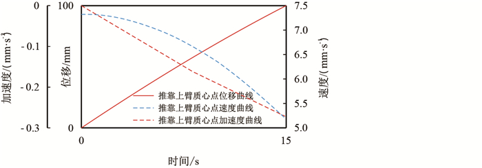 |
| 图10 推靠上臂质心运动曲线 Fig. 10 Curve of cent roid motion of push arm |
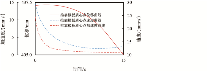 |
| 图11 推靠极板质心运动曲线 Fig. 11 Curve of cent roid motion of push plate |
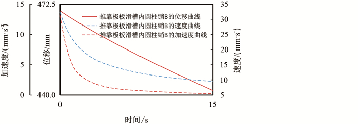 |
| 图12 推靠极板滑槽内圆柱销 Fig. 12 Motion curve of cylindrical pin B in pushing slot by push plate |
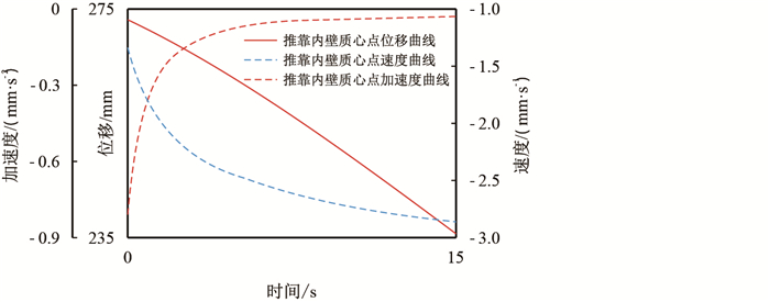 |
| 图13 推靠内臂质心运动曲线 Fig. 13 Moving curve of cent roid of inner arm |
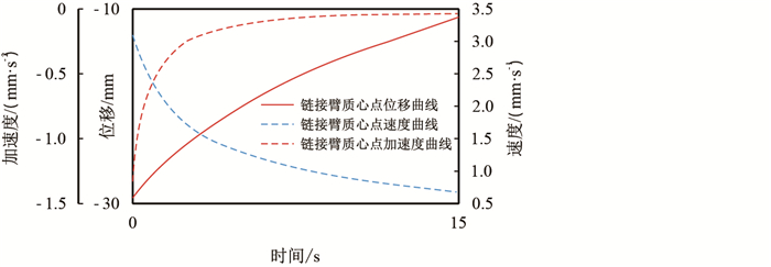 |
| 图14 链接臂质心运动曲线 Fig. 14 Link arm cent roid motion curve |
图 15
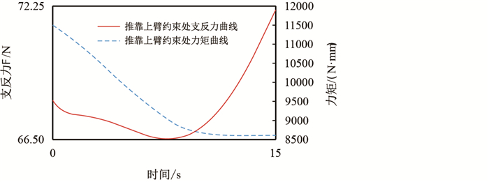 |
| 图15 推靠上臂约束副处支反力、力矩曲线 Fig. 15 Support force and torque curve of restraint pair |
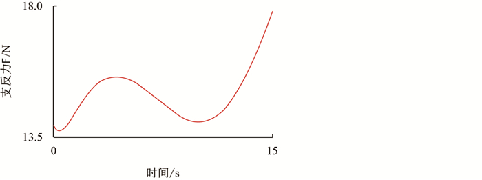 |
| 图16 推靠极板约束副处支反力曲线 Fig. 16 Support force curve at the side of push plate restraint |
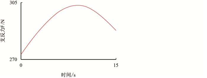 |
| 图17 推靠内臂约束副处支反力曲线 Fig. 17 Support force at the side of the inner arm restraint pair |
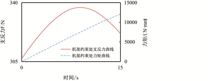 |
| 图18 机架约束副处的支反力、力矩曲线 Fig. 18 Support force and torque curve of frame restraint pair |
(1) 根据仿真结果中位移,速度,加速度曲线图像图 10中可以看出,推靠上臂在驱动力作用下以匀角速度开始转动,质心速度,加速度保持恒定。图 11中推靠极板在推靠上臂的牵连下开始运动,在0
(2) 图 12中滑块
(3) 通过对推靠系统的运动仿真分析,得出各部件的运动规律与约束副处支反力,力矩之间的关系。特别指出滑块
(1) 基于闭环矢量链法建立了微球推靠系统的运动、动力学分析数学模型。利用数值计算方法对微球推靠系统的运动、动力学数学模型进行计算分析,得出推靠系统中各部件的位移,速度,加速度曲线图像以及构件间动力学参数,揭示了微球推靠系统的运动规律与动力特性,校验了所建立的数理模型的合理性。
(2) 通过ADAMS平台进行了微球推靠系统样机模型的运动分析以及动力仿真,通过将仿真结果与数值分析结果比对分析,进一步验证了所建立的微球推靠系统运动及动力学模型的正确性。
(3) 通过仿真计算获取了推靠系统极板处柱销滑槽高副机构的运动规律以及机构中输出构件推靠极板等核心运动部件的运动及动力曲线,为推靠系统的结构参数优化设计提供参数支撑。为后续的柱销滑槽副的优化设计以及微球极板贴合井壁的情况建立了理论分析平台。
| [1] |
鲍忠利, 于会媛, 侯洪为. 常见测井仪器推靠器结构综述[J]. 石油矿场机械, 2010, 39(5): 84-88. BAO Zhongli, YU Huiyuan, HOU Hongwei. Sidewall contact device summary of common logging tool[J]. Oil Field Equipment, 2010, 39(5): 84-88. doi: 10.3969/j.issn.-1001-3482.2010.05.024 |
| [2] |
王利宁, 陈草棠, 包德洲, 等. 微电阻率井径组合仪单电机双驱动推靠器设计[J]. 测井技术, 2013, 37(6): 667-670. WANG Lining, CHEN Caotang, BAO Dezhou, et al. Design of pushing device for single motor double drive of micro-electrode caliper logging tool[J]. Well Logging Technology, 2013, 37(6): 667-670. doi: 10.3969/j.issn.1004-1338.2013.06.017 |
| [3] |
杨柏青. 单臂推靠器的力学探讨[J]. 测井技术, 1988, 12(5): 41-46. YANG Boqing. Mechanics in single-arm anchoring system[J]. Well Logging Technology, 1988, 12(5): 41-46. doi: 10.16489/j.issn.1004-1338.1988.05.008 |
| [4] |
石丽云, 王丽蓉, 柳志翔, 等. MSA6240机械推靠器的设计[J]. 石油仪器, 2008, 22(4): 10-12. SHI Liyun, WANG Lirong, LIU Zhixiang, et al. Design of MSA6240 mechanical sidewall contact devicec[J]. Petroleum Instruments, 2008, 22(4): 10-12. doi: 10.3969/j.issn.1004-9134.2008.04.004 |
| [5] |
王会来, 杨建玺, 崔凤奎, 等. 新型测井仪推靠装置的设计和分析[J]. 西安科技大学学报, 2009, 29(2): 209-213. WANG Huilai, YANG Jianxi, CUI Fengkui, et al. Design and analysis of pushing device of a new logging instrument[J]. Journal of Xi'an University of Science & Technology, 2009, 29(2): 209-213. doi: 10.3969/j.issn.1672-9315.2009.02.018 |
| [6] |
邢家乐, 刘立. 新型VSP仪器推靠装置结构设计[J]. 煤矿机械, 2009, 30(4): 17-18. XING Jiale, LIU Li. Design of new type VSP jogging tool eccentering machinery[J]. Coal Mine Machinery, 2009, 30(4): 17-18. doi: 10.3969/j.issn.1003-0794.2009.04.008 |
| [7] |
纪新福. 推靠器中多功能连杆机构的设计及应用[J]. 河南师范大学学报(自然科学版), 2001, 29(4): 46-48. JI Xinfu. Design and practice of multifunctional linkage in propeller[J]. Journal of Henan Normal University (Natural Science), 2001, 29(4): 46-48. doi: 10.3969/j.issn.1000-2367.2001.04.011 |
| [8] |
邢家乐, 刘立. 基于ADAMS的新型VSP仪器推靠机构仿真与优化[J]. 石油化工高等学校学报, 2009, 22(3): 75-78, 82. XING Jiale, LIU Li. Simulation and optimization for new type VSP logging tool eccentering machinery based on ADAMS[J]. Journal of Petrochemical Universities, 2009, 22(3): 75-78, 82. doi: 10.3969/j.issn.1006-396X.2009.-03.018 |
| [9] |
赵斌. 基于MATLAB的VSP测井仪推靠机构的优化设计[J]. 石油矿场机械, 2008, 37(6): 42-45. ZHAO Bin. Optimization design for VSP jogging tool of eccentering machinery based on MATLAB[J]. Oil Field Equipment, 2008, 37(6): 42-45. doi: 10.3969/j.issn.1001-3482.2008.06.012 |
| [10] |
廖启征. 连杆机构运动学几何代数求解综述[J]. 北京邮电大学学报, 2010, 33(4): 1-11. LIAO Qizheng. Geometry algebra method for solving the kinematics of linkage mechanisms[J]. Journal of Beijing University of Posts and Telecommunications, 2010, 33(4): 1-11. doi: 10.3969/j.issn.1007-5321.2010.04.001 |
| [11] |
拓耀飞, 李少宏. 弹性连杆机构的动力学分析及其仿真[J]. 机械设计, 2016, 33(2): 35-38. TUO Yaofei, LI Shaohong. Research on the dynamic analysis and simulation of elastic linkage mechanism[J]. Journal of Machine Design, 2016, 33(2): 35-38. |
| [12] |
PENNOCK G R, ISRAR A. Kinematic analysis and synthesis of an adjustable six-bar linkage[J]. Mechanism & Machine Theory, 2009, 44(2): 306-323. doi: 10.1016/j.-mechmachtheory.2008.04.007 |
| [13] |
杨开平, 史耀耀, 王丽平. 平面六杆机构运动学仿真系统研究[J]. 计算机仿真, 2011, 28(5): 367-370, 383. YANG Kaiping, SHI Yaoyao, WANG Liping. Research on planar six-bar mechanism's Kinematics simulation system[J]. Computer Simulation, 2011, 28(5): 367-370, 383. doi: 10.3969/j.issn.1006-9348.2011.05.089 |
| [14] |
苏有良. 偏置摆动导杆机构的解析设计与运动仿真[J]. 机械设计, 2013, 30(10): 21-24. SU Youliang. Bias swing guide rod institutions analytic design and motion simulation[J]. Journal of Machine Design, 2013, 30(10): 21-24. doi: 10.3969/j.issn.1001-2354.-2013.10.005 |
| [15] |
龚小平. 平面六杆机构优化设计与运动仿真[J]. 空军工程大学学报(自然科学版), 2012, 13(6): 71-74. GONG Xiaoping. Optimization design of planar six-bar linkage and motion simulation[J]. Journal of Air Force Engineering University (Natural Science Edition), 2012, 13(6): 71-74. doi: 10.3969/j.issn.1009-3516.2012.06.015 |
| [16] |
吴庆鸣, 贾飞, 杨威. 砌块机振动装置动力学仿真分析[J]. 中国机械工程, 2008, 19(18): 2185-2188. WU Qingming, JIA Fei, YANG Wei. Dynamics simulation analysis of the vibration device of block forming machine[J]. China Mechanical Engineering, 2008, 19(18): 2185-2188. doi: 10.3321/j.issn:1004-132X.2008.18.011 |
| [17] |
金国光, 秦凯旋, 魏展, 等. 剑杆织机柔性从动件共轭凸轮打纬机构动力学分析[J]. 纺织学报, 2016, 37(5): 137-142. JIN Guoguang, QIN Kaixuan, WEI Zhan, et al. Dynamic analysis of flexible follower conjugate cam beating-up mechanism in rapier loom[J]. Journal of Textile Research, 2016, 37(5): 137-142. doi: 10.13475/j.fzxb.20150401206 |
| [18] |
任涛, 孙文. 变参数四连杆机构运动及动力性能研究[J]. 机械设计与制造, 2016(6): 96-99. REN Tao, SUN Wen. Study on the Kinematic and dynamic performance of variable parameter four-bar linkage mechanism[J]. Machinery Design & Manufacture, 2016(6): 96-99. doi: 10.3969/j.issn.1001-3997.2016.06.-027 |
| [19] |
MEHDIGHOLI H, AKBARNEJAD S. Optimization of watt's six-bar linkage to generate straight and parallel leg motion[J]. International Journal of Advanced Robotic Systems, 2008, 5(5): 1515-1521. doi: 10.5772/50917 |
| [20] |
SODHI R S, RUSSELL K. Kinematic synthesis of planar four-bar mechanisms for multi-phase motion generation with tolerances[J]. Mechanics Based Design of Structures & Machines, 2004, 32(2): 215-233. |
 2019, Vol. 41


