2. 中国石油大学(北京)石油工程学院, 北京 昌平 102249
2. College of Petroleum Engineering, China University of Petroleum(Bejing), Changping, Beijing 102249, China
随着油田注水开发技术的日益发展和完善,如何准确计算不同注采方式内部流场分布,探明不同注采方式内部等势线和流线分布规律对于完善注采井网、合理部署加密井位具有重要意义[1-4]。前人关于注采井网的理论研究主要集中在产能计算和井网形式优化方面[5-9]。本文以工程实际需求为导向,基于直井水平井一注一采、水平井一注一采、水平井两注一采3种注采方式,采用保角变换和镜像反映方法,建立并求解不同注采方式流场数学模型,通过绘制不同注采方式等势线和流线分布图明确各注采方式内部流场分布规律。以此为基础,通过开展不同注采方式下水驱油物理模拟实验研究,观测不同平板模型注采井间流场分布形态特征,并与不同注采方式流场计算模型计算结果进行相互验证。
1 不同注采方式流场计算模型 1.1 直井水平井一注一采注采方式流场计算模型如图 1所示,
| $ \left\{ \begin{array}{l} x=L{\rm ch}~\xi \cos\eta \\ y=L{\rm sh}~\xi \sin\eta \end{array} \right. $ |
 |
| 图1 直井水平井一注一采示意图 Fig. 1 A schematic map of one vertical injector and one horizontal producer |
将
根据镜像反映原理,将
镜像反映所得到的井点坐标为:
| $ {{\varPhi }_{1}}={{q}_1}({{A}_{1}}+{{A}_{2}}+{{A}_{3}})+{{\rm C}_{1}} $ | (1) |
| $ {{A}_{1}}=\sum\limits_{n=1}^{+\infty }{\ln \left[\left( \xi +{{\xi }_{0}} \right)+{\rm i}\left( \eta +{{\eta }_{0}} \right)-{\rm i}n\pi \right]}+\\ {\kern 40pt } \sum\limits_{n=1}^{+\infty }{\ln \left[\left( \xi +{{\xi }_{0}} \right)+{\rm i}\left( \eta-{{\eta }_{0}} \right)+{\rm i}n\pi \right]} $ | (2) |
| $ {{A}_{2}}=\ln \left[\left( \xi +{{\xi }_{0}} \right)+{\rm i}\left( \eta-{{\eta }_{0}} \right) \right]- \\ {\kern 40pt } \sum\limits_{n=1}^{+\infty }{\ln \left[\left( \xi-{{\xi }_{0}} \right)+{\rm i}\left( \eta +{{\eta }_{0}} \right)-{\rm i}n\pi \right]} $ | (3) |
| $ {{A}_{3}}=-\sum\limits_{n=1}^{+\infty }{\ln \left[\left( \xi-{{\xi }_{0}} \right)+{\rm i}\left( \eta-{{\eta }_{0}} \right)+{\rm i}n\pi \right]}-\\ {\kern 40pt } \sum\limits_{n=1}^{+\infty } {\ln \left[\left( \xi +{{\xi }_{0}} \right)+{\rm i}\left( \eta-{{\eta }_{0}} \right) \right]} $ | (4) |
式中:
根据势函数与复势函数的关系,得到势函数的表达式
| $ {\phi _1}{\rm{ = }}\frac{{{q_1}}}{2}\ln \frac{{{\rm{ch}}\;{\rm{2}}\left( {\xi + {\xi _0}} \right)-\cos \;2\left( {\eta + {\eta _0}} \right)}}{{{\rm{ch}}\;{\rm{2}}\left( {\xi-{\xi _0}} \right)-\cos \;2\left( {\eta + {\eta _0}} \right)}}+{{\rm{C}}_2}$ | (5) |
式中:
C2——常数。
根据式(2),绘制直井水平井一注一采井网等势线分布图(图 2)。
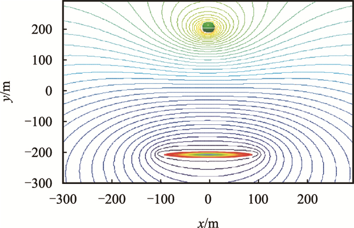 |
| 图2 直井水平井一注一采等势线分布图 Fig. 2 Equipotential line pattern for one vertical well injection and one horizontal well production |
根据流函数与势函数的关系
| $ \left\{ \begin{array}{l} \dfrac{\partial {{\phi }_{1}}}{\partial \xi }=\dfrac{\partial {{\varphi }_{1}}}{\partial \eta } \\ \dfrac{\partial {{\varphi }_{1}}}{\partial \xi }=-\dfrac{\partial {{\phi }_{1}}}{\partial \eta } \end{array} \right. $ | (6) |
得到流函数表达式
| $ {{\varphi }_{1}}={{q}} \operatorname{arctan}\dfrac{\operatorname{sh}(\mathop{\xi }_{1}+\xi )\operatorname{tan}\eta }{\mathop{\operatorname{{\rm ch}}(\mathop{\xi }_{1}+\xi )}^{{}}}-\\{\kern 40pt}{{q}}\operatorname{arctan}\dfrac{\left| \operatorname{sh}(\mathop{\xi }_{1}-\xi )\operatorname{tan}\eta \right|}{\mathop{\operatorname{{\rm ch}}(\mathop{\xi }_{1}-\xi )}^{{}}} +{\rm C} $ | (7) |
式中:
C——常数。
根据式(4)绘制直井水平井一注一采流线分布图见图 3。流线在直井与水平井中心连线区域较为密集,该区域驱替效果相对较好。
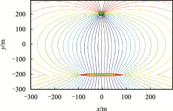 |
| 图3 直井水平井一注一采流线分布图 Fig. 3 Stream line pattern for one vertical well injection and one horizontal well production |
由于水平注入井(水平生产井)可以看作是有一系列均匀分布的点源(汇)所组成的线源(汇)[12],因此,其势函数分布和流函数分布可以通过对直井的势函数和流函数进行积分得到。图 4为水平井一注一采井网分布图,注入井和生产井平行正对,两井中心位置在一条直线上,其中心坐标分别为
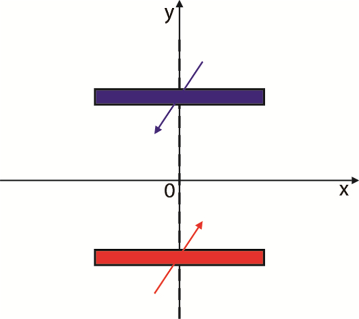 |
| 图4 水平井一注一采示意图 Fig. 4 A schematic map of one vertical well injection and one horizontal well production |
根据叠加原理,水平井一注一采注采方式势函数为
| $ {{\phi }_{2}}=\dfrac{1}{4\pi L} \sum\limits_{i=1}^{2}{q_{i}{'}}({{A}_{4}}+{{A}_{5}}+{{A}_{6}}) $ | (8) |
| $ {{A}_{4}}=\left[{\rm arccot} \dfrac{x-\left( {{x}_{{\rm w}i}}+L \right)}{ y-{{y}_{{\rm w}i}} }-{\rm arccot} \dfrac{x-\left( {{x}_{{\rm w}i}}-L \right)}{ y-{{y}_{{\rm w}i}} } \right]\cdot \\ {\kern 40pt} \dfrac{y-{{y}_{{\rm w}i}}}{L} $ | (9) |
| $ {{A}_{5}}= \dfrac{x-{{x}_{{\rm w}i}}}{2L} \ln \dfrac{{{\left[x-\left( {{x}_{{\rm w}i}}-L \right) \right]}^{2}}+{{\left( y-{{y}_{{\rm w}i}} \right)}^{2}}}{{{\left[x-\left( {{x}_{{\rm w}i}}+L \right) \right]}^{2}}+{{\left( y-{{y}_{{\rm w}i}} \right)}^{2}}} $ | (10) |
| $ {A_6} = \dfrac{1}{2}\ln \left[{{{\left( {x-{x_{{\rm{w}}i}}{\rm{ + }}L} \right)}^2} + {{\left( {y-{y_{{\rm{w}}i}}} \right)}^2}} \right] +\\ {\kern 40pt} \dfrac{1}{2}\ln \left[{{{\left( {x-{x_{{\rm{w}}i}}-L} \right)}^2} + {{\left( {y-{y_{{\rm{w}}i}}} \right)}^2}} \right] $ | (11) |
式中:
下标
利用流函数与势函数的关系,可以得到水平井的流函数
| $ {{\varphi }_{2}}=\dfrac{1}{2\pi L} \sum\limits_{i=1}^{2}{{{q}_{i}{'}}}({{B}_{1}}+{{B}_{2}}+{{B}_{3}}) $ | (12) |
| $ {{B}_{1}}=\left[x-\left( {{x}_{{\rm w}i}}+L \right) \right]{\rm arccot} \dfrac{\left[x-\left( {{x}_{{\rm w}i}}+L \right) \right]}{y-{{y}_{{\rm w}i}}} $ | (13) |
| $ {{B}_{2}}=-\left[x-\left( {{x}_{{\rm w}i}}-L \right) \right]{\rm arccot} \dfrac{\left[x-\left( {{x}_{{\rm w}i}}-L \right) \right]}{y-{{y}_{{\rm w}i}}} $ | (14) |
| $ {{B}_{3}}=\dfrac{ y-{{y}_{{\rm w}i}} }{2}\ln \dfrac{{{\left[x-\left( {{x}_{{\rm w}i}}+L \right) \right]}^{2}}+{{\left( y-{{y}_{{\rm w}i}} \right)}^{2}}}{\left[x-\left( {{x}_{{\rm w}i}}-L \right) \right]+{{\left( y-{{y}_{{\rm w}i}} \right)}^{2}}} $ | (15) |
根据式(5)和式(8)分别绘制水平井一注一采注采方式内部等势线和流线分布图(图 5,图 6)。
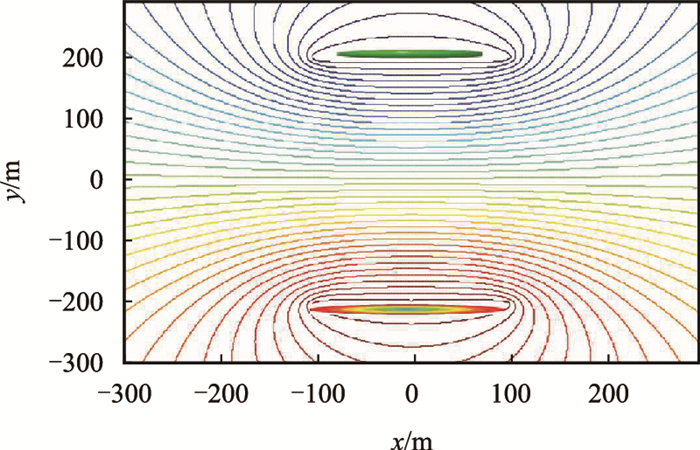 |
| 图5 水平井一注一采等势线 Fig. 5 Equipotential line pattern for one horizontal injection and one horizontal well production |
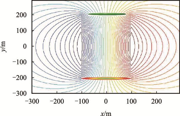 |
| 图6 水平井一注一采流线分布图 Fig. 6 Stream line pattern for one horizontal injection and one horizontal well production |
与直井注水平井采注采方式的流线分布特征对比发现,水平井注采方式流线在水平注采井间密集分布,水驱波及效率明显高于直井注水平井采。
1.3 水平井两注一采注采方式流场计算模型水平井两注一采井网分布如图 7所示,注入井和生产井平行,两注入井井中心位置在一条直线上,且水平井长度相同,均为2L,中心坐标分别为
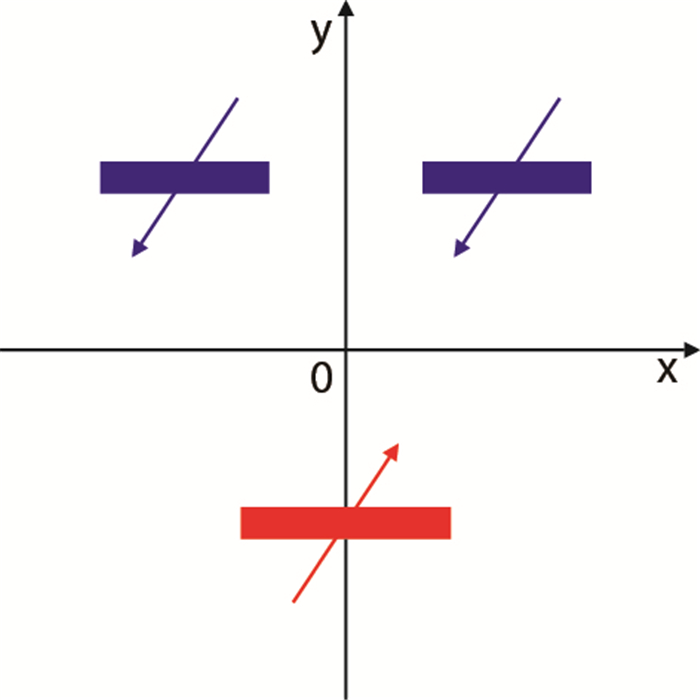 |
| 图7 水平井两注一采示意图 Fig. 7 A schematic map of two horizontal injection and one horizontal production |
采用与水平井一注一采注采方式相同的方法,得到水平井两注一采注采方式的势函数和流函数
| $ {{\phi }_{3}}=\dfrac{1}{4\pi L}\times \sum\limits_{i=1}^{3}{{q_{i}{''}}}({{A}_{4}}+{{A}_{5}}+{{A}_{6}}) $ | (16) |
| $ {{\varphi }_{3}}=\dfrac{1}{2\pi L}\times \sum\limits_{i=1}^{3}{{q_{i}{''}}}({{B}_{1}}+{{B}_{2}}+{{B}_{3}}) $ | (17) |
式中:
基于式(11)和式(12),得到水平井两注一采情况下的等势线(图 8)和流线(图 9)分布图。
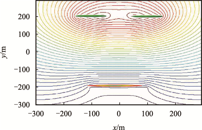 |
| 图8 水平井两注一采等势线 Fig. 8 Equipotential line pattern for two horizontal injection and one horizontal well production |
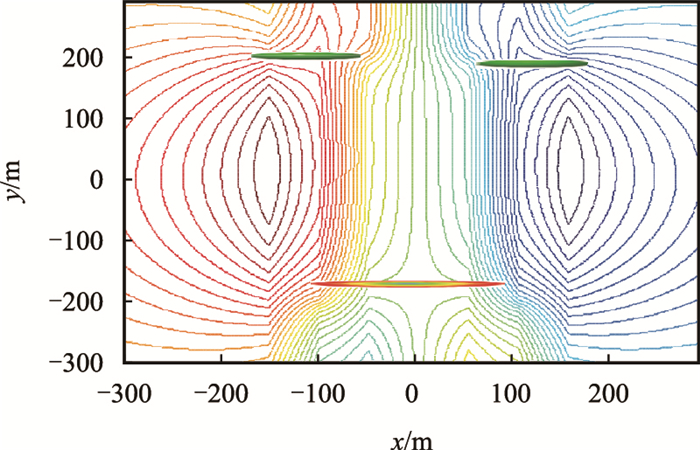 |
| 图9 水平井两注一采流线分布图 Fig. 9 Stream line pattern for two horizontal injection and one horizontal well production |
水平井两注一采内部流线集中分布在水平生产井跟端和趾端与两口注入井正对区域。在两口注入井中间区域流线分布稀疏,注入水难以波及该区域,容易形成滞油区。
2 不同注采方式流场计算模型物理模拟验证为验证不同注采方式流场计算模型的可靠性,开展了不同注采方式流场平板模型物理模拟实验,直观反映不同注采方式内部流场分布特征。
2.1 三维平板模型实验方法针对直井水平井一注一采、水平井一注一采、水平井两注一采3种注采方式分别制备相应的平板模型,三维平板模型尺寸为40 cm×40 cm×3 cm,均质填砂(渗透率3 000 mD),实验前将模型抽真空,并将模型充分饱和模拟地层水后饱和模拟油[13-15],实验过程中控制注入端注入速度1 mL/min,当模型含水率达到90%时,驱替结束,观察不同注采系统内部流场分布规律。实验流程见图 10。
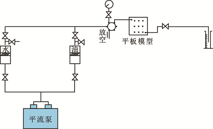 |
| 图10 不同注采方式流场物理模拟实验流程 Fig. 10 Flow chart of different injection production well pattern flow field experiment |
不同注采方式平板模型物理模拟流场分布特征与基于计算模型绘制的各流场分布特征具有很好的一致性(图 11)。
 |
| 图11 不同注采方式物理模拟流场分布图 Fig. 11 Flow field of different injection production well pattern by experiment |
物理模拟流场分布特征与基于计算模型绘制的各流场分布特征均表现出以下共性特征:直井水平井一注一采内部流场表现出一定的线性流,水驱波及面积较常规直井注采方式有所增大。水平井一注一采内部注采井间流线呈线性流,与直井水平井一注一采相比,流线控制的面积进一步增大,驱替效果更好。水平井两注一采内部水平生产井跟端和趾端附近流线较为密集,水平生产井中部位置附近流线相对稀疏易形成滞油区。直井注水平井采、水平井一注一采、水平井两注一采3种注采方式在含水达到90%时的水驱波及系数分别为46%、65%和73%,水平井两注一采水驱效果好于水平井一注一采注采方式,直井注水平井采波及效率相对较低。
3 结论(1) 基于保角变换和镜像反映原理,建立并求解了不同注采方式流场计算数学模型,绘制了不同注采方式内部等势线和流线分布图。
(2) 不同注采方式内部流场平板模型物理模拟实验,直观反映了不同注采方式内部流场分布形态,此验证了流场计算模型的正确性。
(3) 直井水平井一注一采内部流场表现出一定的线性流,水驱波及面积较常规直井注采方式有所增大。水平井一注一采内部注采井间流线呈线性流,与直井水平井一注一采相比,流线控制的面积进一步增大,驱替效果更好。水平井两注一采内部水平生产井跟端和趾端附近流线较为密集,水平生产井中部位置附近流线相对稀疏易形成滞油区。
| [1] |
叶双江, 姜汉桥, 李俊键, 等. 混合井网条件下加密井产能计算模型及应用[J].
计算物理, 2011, 28(5): 693–697.
YE Shuangjiang, JIANG Hanqiao, LI Junjian, et al. Productivity calculation of infill horizontal wells in mixed well pattern[J]. Chinese Journal of Computational Physics, 2011, 28(5): 693–697. doi: 10.3969/j.issn.1001-246X.2011.05.008 |
| [2] |
宋文玲, 冯凤萍, 赵春森, 等. 水平井和分支水平井与直井混合井网产能计算方法[J].
大庆石油学院学报, 2004, 28(2): 107–109.
SONG Wenling, FENG Fengping, ZHAO Chunsen, et al. Productivity calculation method for horizontal well and branch horizontal well and vertical well mixed well pattern[J]. Journal of Daqing Petroleum Institute, 2004, 28(2): 107–109. doi: 10.3969/j.issn.2095-4107.2004.02.036 |
| [3] |
郑伟, 姜汉桥, 陈民锋, 等. 低渗透油藏混合井网系统合理注采井距确定[J].
新疆石油地质, 2010, 31(6): 637–639.
ZHENG Wei, JIANG Hanqiao, CHEN Minfeng, et al. Study on proper well spacing of hybrid pattern of vertical injector and horizontal producer in low permeability reservoir[J]. Xinjiang Petroleum Geology, 2010, 31(6): 637–639. |
| [4] |
赵继勇, 何永宏, 樊建明, 等. 超低渗透致密油藏水平井井网优化技术研究[J].
西南石油大学学报(自然科学版), 2014, 36(2): 91–97.
ZHAO Jiyong, HE Yonghong, FAN Jianming, et al. Optimization technology for horizontal well pattern in ultra-low permeable tight reservoirs[J]. Journal of Southwest Petroleum University (Science & Technology Edition), 2014, 36(2): 91–97. doi: 10.11885/j.issn.1674-5086.2012.05.03.01 |
| [5] |
周瀛, 唐海, 吕栋梁, 等. 排状交错水平井井网面积波及效率研究[J].
岩性油气藏, 2012, 24(5): 124–128.
ZHOU Ying, TANG Hai, LÜ Dongliang, et al. Areal sweep efficiency of staggered well pattern of horizontal wells in low permeability reservoirs[J]. Lithologic Reservoirs, 2012, 24(5): 124–128. doi: 10.3969/j.issn.1673-8926.2012.05.028 |
| [6] |
张枫, 李治平, 董萍, 等. 水平井整体开发井网研究[J].
天然气地球科学, 2007, 18(4): 621–625.
ZHANG Feng, LI Zhiping, DONG Ping, et al. Horizontal well pattern research[J]. Natural Gas Geoscience, 2007, 18(4): 621–625. doi: 10.3969/j.issn.1672-1926.-2007.04.029 |
| [7] | CHARLES D D, STARTZMAN R A. Streamtube modeling of horizontal wells in mixed pattern waterfloods[C]. SPE 23451-MS, 1991. doi: 10.2118/23451-MS http://www.researchgate.net/publication/241786938_streamtube_modeling_of_horizontal_wells_in_mixed_pattern_waterfloods |
| [8] | ALGHARAIB M, ERTEKIN T. The efficiency of horizontal and vertical well patterns in waterflooding: A numerical study[C]. SPE 52196-MS, 1999. doi: 10.2118/52196-MS https://www.researchgate.net/publication/266668490_The_Efficiency_of_Horizontal_and_Vertical_Well_Patterns_in_Waterflooding_A_Numerical_Study |
| [9] | ABDELGAWAD A, MALEKZADEH D. Determination of the drainage area of horizontal wells in the presence of vertical wells:Effect of reservoir and well parameters[J]. JCPT, 2001, 40(10): 45–54. doi: 10.2118/01-10-02 |
| [10] |
王锦森.
复变函数[M]. 北京: 高等教育出版社, 2013.
WANG Jinsen. Complex function[M]. Beijing: High Education Press, 2013. |
| [11] |
张建国, 雷光伦, 张艳玉.
油气层渗流力学[M]. 东营: 石油大学出版社, 1998.
ZHANG Jianguo, LEI Guanglun, ZHANG Yanyu. Fluid mechanics in oil and gas reservoirs[M]. Dongying: Petroleum University Press, 1998. |
| [12] |
程林松.
渗流力学[M]. 北京: 石油工业出版社, 2011.
CHENG Linsong. Fluid mechanics in porous medium[M]. Beijing: Petroleum Industry Press, 2011. |
| [13] |
汤勇, 孙雷, 戚志林, 等. 反凝析油临界流动饱和度的长岩心实验测定方法[J].
天然气工业, 2006, 26(7): 100–102.
TANG Yong, SUN Lei, QI Zhilin, et al. Measurement on critical condensate saturation using long core flooding experiment[J]. Natural Gas Industry, 2006, 26(7): 100–102. doi: 10.3321/j.issn:1000-0976.2006.07.033 |
| [14] |
肖康, 姜汉桥, 李俊键, 等. 应用水平井动用储层顶部剩余油物理模拟[J].
特种油气藏, 2013, 20(3): 127–131.
XIAO Kang, JIANG Hanqiao, LI Junjian, et al. Physical model of producing remaining oil from top reservoir by horizontal well[J]. Special Oil & Gas Reservoirs, 2013, 20(3): 127–131. doi: 10.3969/j.issn.1006-6535.2013.03.031 |
| [15] |
唐洪明, 文鑫, 张旭阳, 等. 层间非均质砾岩油藏水驱油模拟实验[J].
西南石油大学学报(自然科学版), 2014, 36(5): 129–135.
TANG Hongming, WEN Xin, ZHANG Xuyang, et al. Water-oil displacing modeling experiment of interlayer heterogeneous conglomerate reservoir[J]. Journal of Southwest Petroleum University (Science & Technology Edition), 2014, 36(5): 129–135. doi: 10.11885/j.issn.1674-5086.2012.06.06.02 |
 2018, Vol. 40


