2. 西南石油大学理学院, 四川 成都 610500
2. School of Sciences, Southwest Petroleum University, Chengdu, Sichuan 610500, China
在油田开发中后期,油藏压力降低,通常采用注水来维持地层压力并且提高采收率[1-3]。然而,由于注入水和地层水不相容,会产生结垢沉淀,例如:CaSO
油田结垢预测模型主要有3类:(1) 定性结垢预测公式,以饱和指数为基础,主要有Rynar稳定指数法[7]、D-S饱和指数法和Oddo-Tomson指数法[8-9];(2) 以热力学平衡原理为基础的热力学结垢模型,如pitzer离子相互作用模型[10]、UNIQUAC通用似化学模型[11];(3) 基于动力学原理的结垢预测模型,Bedrikovetsky[12-16]根据化学反应速率方程和物质的对流扩散方程建立了预测硫酸钡结垢的动力学模型。
以饱和指数为基础的定性结垢预测公式是经验公式,准确性不高;以热力学平衡原理建立的模型,没有考虑注水驱替时的动力学因素。本文以Bedrikovetsky的动力学模型为基础,在瞬态模型中考虑了扩散项,优化了求解模型参数的方法,并采用数值方法求解,得出驱替至不同PV时岩芯中结垢量的分布。
1 模型假设(1) 注入水中的SO
(2) 硫酸钡瞬时沉积,且生成的沉淀不随水流运移。
(3) 注入水与地层水不可压缩。
(4) 化学反应速率常数
(5) 岩芯的孔隙度ϕ和渗透率
影响硫酸钡结垢的因素主要有:对流、扩散和沉淀反应[17],因此在建立的控制方程中应该包括对流项、扩散项和反应项。注入水与地层水混合产生沉淀的流动控制方程应包括SO
| $ \left\{ \begin{array}{l} \phi \dfrac{{\partial c_{{\rm{Ba}}^{2 + } } }}{{\partial t}} + U\dfrac{{\partial c_{{\rm{Ba}}^{2 + } } }}{{\partial x}} = D\dfrac{{\partial ^2 c_{{\rm{Ba}}^{2 + } } }}{{\partial x^2 }} - K_{\rm{a}} c_{{\rm{Ba}}^{2 + } } c_{{\rm{SO}}_4^{2 - } } \\[8pt] \phi \dfrac{{\partial c_{{\rm{SO}}_4^{2 - } } }}{{\partial t}} + U\dfrac{{\partial c_{{\rm{SO}}_4^{2 - } } }}{{\partial x}} = D\dfrac{{\partial ^2 c_{{\rm{SO}}_4^{2 - } } }}{{\partial x^2 }} - K_{\rm{a}} c_{{\rm{Ba}}^{2 + } } c_{{\rm{SO}}_4^{2 - } } \\[8pt] \phi \dfrac{{\rho _{_{\rm{BaSO_4}} } }}{{M_{_{{\rm{BaSO}}_4 } } }}\dfrac{{\partial \sigma }}{{\partial t}} = K_{\rm{a}} c_{{\rm{Ba}}^{2 + } } c_{{\rm{SO}}_4^{2 - } } \\ \end{array} \right. $ | (1) |
驱替开始时岩芯中已饱和富含Ba
| $ c_{{\rm{Ba}}^{2 + } } = c_{{\rm{Ba}}^{2 + } }^0 {\rm{, }}~~~c_{{\rm{SO}}_4^{2 - } } = 0 $ |
当富含SO
| $ c_{{\rm{Ba}}^{2 + } } = 0{\rm{, }}~~~c_{{\rm{SO}}_4^{2 - } } = c_{{\rm{SO}}_4^{2 - } }^0 $ |
假设流体在岩芯出口流出,无倒流发生,则岩芯出口端的边界条件为
为了消除模型中不同参数之间数量级的差异,需要首先定义无因次参数
| $ c_{{\rm{Ba}}^{2+}}^{*}=\dfrac{{c_{{\rm{Ba}}^{{\rm{2 + }}} } }}{{c_{{\rm{Ba}}^{{\rm{2 + }}} }^0 }};{\rm{ }}c_{{\rm{SO}}_{\rm{4}}^{{\rm{2 - }}} }^{*} = \dfrac{{c_{{\rm{SO}}_{\rm{4}}^{{\rm{2 - }}} } }}{{c_{{\rm{SO}}_{\rm{4}}^{{\rm{2 - }}} }^0 }}{\rm{ }}\\ {{S}} = \dfrac{{\rho_{_{\rm{BaSO_{\rm{4}}}} } }}{{M_{_{{\rm{BaSO}}_{\rm{4}} } } }}\dfrac{\sigma }{{c_{{\rm{Ba}}^{{\rm{2 + }}} }^0 }};{\rm{ }}c^0 = \dfrac{{c_{{\rm{Ba}}^{{\rm{2 + }}} }^0 }}{{c_{{\rm{SO}}_{\rm{4}}^{{\rm{2 - }}} }^0 }};x_{\rm{d}} = \dfrac{x}{L}{\rm{ }};$ |
将定义的无因次参数代入式(1),得到的无因次控制方程如式(2) 所示
| $ \left\{ \begin{array}{l} \dfrac{{\partial c_{{\rm{Ba}}^{{\rm{2 + }}} }^* }}{{\partial t_{\rm{d}} }} + \dfrac{{\partial c_{{\rm{Ba}}^{{\rm{2 + }}} }^* }}{{\partial x_{\rm{d}} }} = \varepsilon _{\rm{D}} \dfrac{{\partial ^2 c_{{\rm{Ba}}^{{\rm{2 + }}} }^* }}{{\partial x_{\rm{d}} ^2 }} - \varepsilon _{\rm{k}} c_{{\rm{Ba}}^{{\rm{2 + }}} }^* c_{{\rm{SO}}_{\rm{4}}^{{\rm{2 - }}} }^* \\[8pt] \dfrac{{\partial c_{{\rm{SO}}_{\rm{4}}^{{\rm{2 - }}} }^* }}{{\partial t_{\rm{d}} }} + \dfrac{{\partial c_{{\rm{SO}}_{\rm{4}}^{{\rm{2 - }}} }^* }}{{\partial x_{\rm{d}} }} = \varepsilon _{\rm{D}} \dfrac{{\partial ^2 c_{{\rm{SO}}_{\rm{4}}^{{\rm{2 - }}} }^* }}{{\partial x_{\rm{d}} ^2 }} - \varepsilon _{\rm{k}} c^0 c_{{\rm{Ba}}^{{\rm{2 + }}} }^* c_{{\rm{SO}}_{\rm{4}}^{{\rm{2 - }}} }^* \\[8pt] \dfrac{{\partial S}}{{\partial t_{\rm{d}} }} = \varepsilon _{\rm{k}} c_{{\rm{Ba}}^{{\rm{2 + }}} }^* c_{{\rm{SO}}_{\rm{4}}^{{\rm{2 - }}} }^* \\[8pt] t_{\rm{d}} = 0:{\rm{ }}c_{{\rm{Ba}}^{{\rm{2 + }}} }^* = 1, {\rm{ }}c_{{\rm{SO}}_{\rm{4}}^{{\rm{2 - }}} }^* = 0 \\[8pt] t_{\rm{d}} > 0, {\rm{ }}x_{\rm{d}} = 0:{\rm{ }}c_{{\rm{Ba}}^{{\rm{2 + }}} }^* = 0, {\rm{ }}c_{{\rm{SO}}_{\rm{4}}^{{\rm{2 - }}} }^* = 1 \\[8pt] t_{\rm{d}} > 0, x_{\rm{d}} = L:\dfrac{{\partial c_{{\rm{Ba}}^{{\rm{2 + }}} }^* }}{{\partial x_{\rm{d}} }} = \dfrac{{\partial c_{{\rm{SO}}_{\rm{4}}^{{\rm{2 - }}} }^* }}{{\partial x_{\rm{d}} }} = 0 \\ \end{array} \right. $ | (2) |
通过以上的控制方程、初始条件和边界条件,可以求出SO
选取2块长庆油田的岩芯,岩芯物性见表 1。
| 表1 岩芯物性数据 Table 1 Physical properties of core samples |
实验使用的注入水和地层水分别为洛河水和H51-20井地层水,注入水中含有较多的SO
| 表2 水样离子成分组成 Table 2 The concentration of the synthetic formation and injection brines |
由表 2可知,地层水中的Ba
岩芯驱替实验的设备和流程如图 1所示。
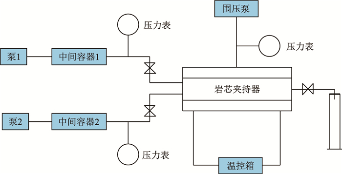 |
| 图1 岩芯驱替实验流程图 Fig. 1 The core-flooding experiment flowchart |
设计岩芯驱替实验,用去除SO
| $ \left\{ \begin{array}{l} \phi \dfrac{{\partial c_{{\rm{Ba}}^{{\rm{2 + }}} } }}{{\partial t}} + U\dfrac{{\partial c_{{\rm{Ba}}^{{\rm{2 + }}} } }}{{\partial x}} = D\dfrac{{\partial ^2 c_{{\rm{Ba}}^{{\rm{2 + }}} } }}{{\partial x^2 }} \\ t = 0:{\rm{ }}c_{{\rm{Ba}}^{{\rm{2 + }}} } = \left\{ \begin{array}{l} 0, {\rm{ }}x \leqslant 0 \\ c_{{\rm{Ba}}^{{\rm{2 + }}} }^0, {\rm{ }}x > 0 \\ \end{array} \right. \\ c_{{\rm{Ba}}^{{\rm{2 + }}} } (x \to - \infty, t) = 0 \\ c_{{\rm{Ba}}^{{\rm{2 + }}} } (x \to + \infty, t) = c_{{\rm{Ba}}^{{\rm{2 + }}} }^0 \\ \end{array} \right. $ | (3) |
微分方程(3) 的解析解如式(4) 所示
| $ c_{{\rm{Ba}}^{{\rm{2 + }}} } (x, t) = c_{{\rm{Ba}}^{{\rm{2 + }}} }^0 - \dfrac{{c_{{\rm{Ba}}^{{\rm{2 + }}} }^0 }}{2}{\rm{erfc}}\left( {\dfrac{{x - Ut/\phi }}{{2\sqrt {Dt/\phi } }}} \right) $ | (4) |
式(4) 的无因次形式可以表示为
| $ c_{{\rm{Ba}}^{{\rm{2 + }}} }^* (x_{\rm{d}}, t_{\rm{d}} ) = 1 - \dfrac{1}{2}{\rm{erfc}}\left( {\dfrac{{x_{\rm{d}} - t_{\rm{d}} }}{{2\sqrt {\varepsilon _{\rm{D}} t_{\rm{d}} } }}} \right) $ | (5) |
式(5) 在
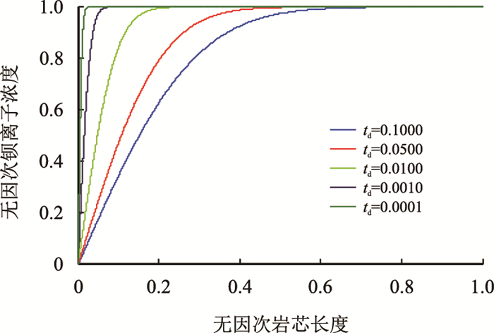 |
|
图2
|
因此,驱替实验中岩芯出口端的无因次Ba
| $ c_{{\rm{Ba}}^{{\rm{2 + }}} }^* (x_{\rm{d}}, t_{\rm{d}} ) = 1 - \dfrac{1}{2}{\rm{erfc}}\left( {\dfrac{{x_{\rm{d}} - t_{\rm{d}} }}{{2\sqrt {\varepsilon _{\rm{D}} t_{\rm{d}} } }}} \right) $ | (6) |
设定驱替流速为0.5 mL/min,在驱替至不同PV时记录岩芯出口端的Ba
|
表3 测定扩散系数时岩芯出口端无因次Ba |
由表 3中的岩芯出口端无因次Ba
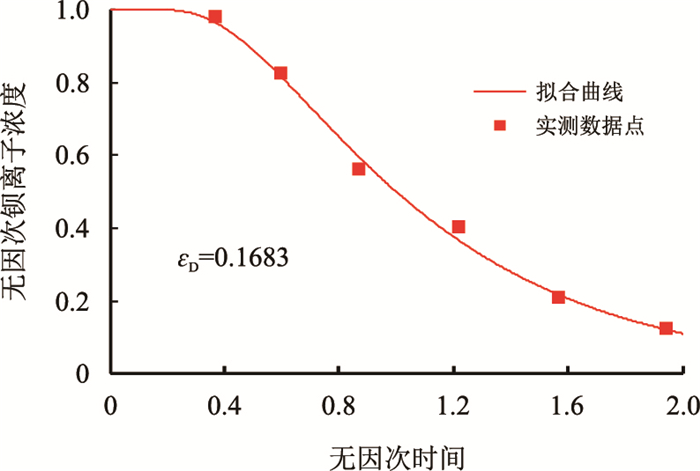 |
| 图3 岩芯1无因次扩散系数拟合结果 Fig. 3 The fitting result of dimensionless diffusion coefficient for No.1 core |
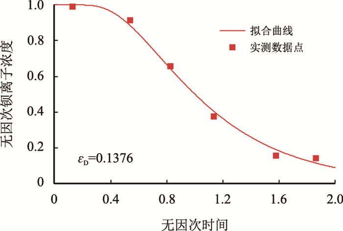 |
| 图4 岩芯2无因次扩散系数拟合结果 Fig. 4 The fitting result of dimensionless diffusion coefficient for No.2 core |
由图 3和图 4可知,当不发生结垢反应时,随着无因次驱替时间
由式(2) 可得1号岩芯和2号岩芯的扩散系数,见表 4。
| 表4 岩芯的扩散系数 Table 4 Diffusion coefficient of the cores |
求取反应速率常数的一种方法是直接对式(2) 求解析解,得出稳态条件下Ba
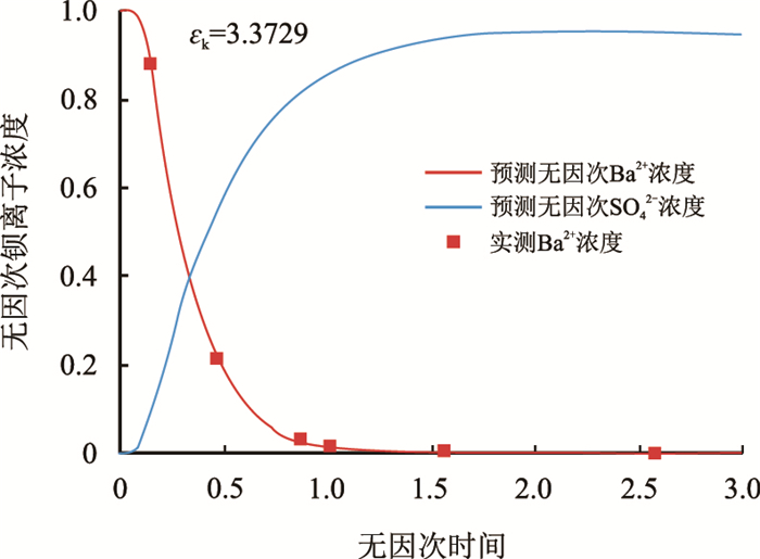
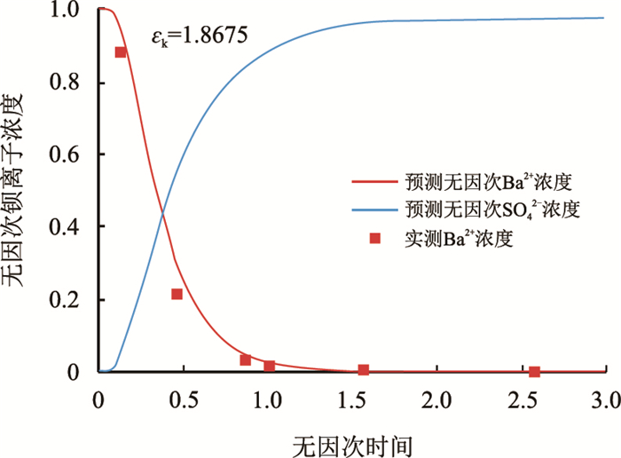
在求取扩散系数时驱替实验中的注入水中不含成垢阴离子,因此岩芯中无结垢发生。将岩芯1和岩芯2再次饱和模拟地层水,利用含有SO
|
表5 测定反应速率常数时岩芯出口端无因次Ba |
定义
| $ \left\{ \begin{array}{l} \dfrac{{{\rm{d}}X_j }}{{{\rm{d}}t_{\rm{d}} }} = \varepsilon _{\rm{D}} \dfrac{{X_{j - 1} - 2X_j + X_{j + 1} }}{{(\Delta x_{\rm{d}} )^2 }} - \dfrac{{X_{j + 1} - X_j }}{{\Delta x_{\rm{d}} }} - \varepsilon _k X_j Y_j {\rm{ }}~~~~~j{\rm{ = 2, 3, }}...N \\[10pt] \dfrac{{{\rm{d}}Y_j }}{{{\rm{d}}t_{\rm{d}} }} = \varepsilon _D \dfrac{{Y_{j - 1} - 2Y_j + Y_{j + 1} }}{{(\Delta x_{\rm{d}} )^2 }} - \dfrac{{Y_{j + 1} - Y_j }}{{\Delta x_{\rm{d}} }} - \varepsilon _k c^0 Y_j X_j {\rm{ }}~~~~~j{\rm{ = 2, 3, }}...N \\ \dfrac{{\partial S}}{{\partial t_{\rm{d}} }} = \varepsilon _k X_j Y_j \\ t_{\rm{d}} = 0, {\rm{ }}X_j = 1, Y_j = 0 \\ j = 1, {\rm{ }}X_1 = 0, Y_1 = 1 \\ j = N + 1, {\rm{ }}X_{N + 1} = X_N, Y_{N + 1} = Y_N \\ \end{array} \right. $ | (7) |
最后,这一初值问题的方程组在
 |
| 图5 岩芯1无因次反应速率常数拟合结果 Fig. 5 The fitting result of dimensionless reaction rate constant for No.1 core |
 |
| 图6 岩芯2无因次反应速率常数拟合结果 Fig. 6 The fitting result of dimensionless reaction rate constant for No.2 core |
由图 5和图 6可知,当含有SO
把无因次反应速率常数代入定义的无因次量中,即可求出岩芯1和岩芯2的反应速率常数,见表 6。
| 表6 岩芯的反应速率常数 Table 6 Reaction rate constant of the cores |
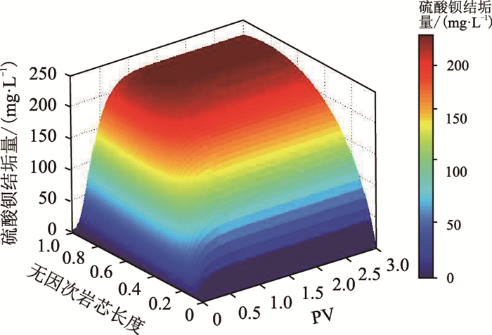
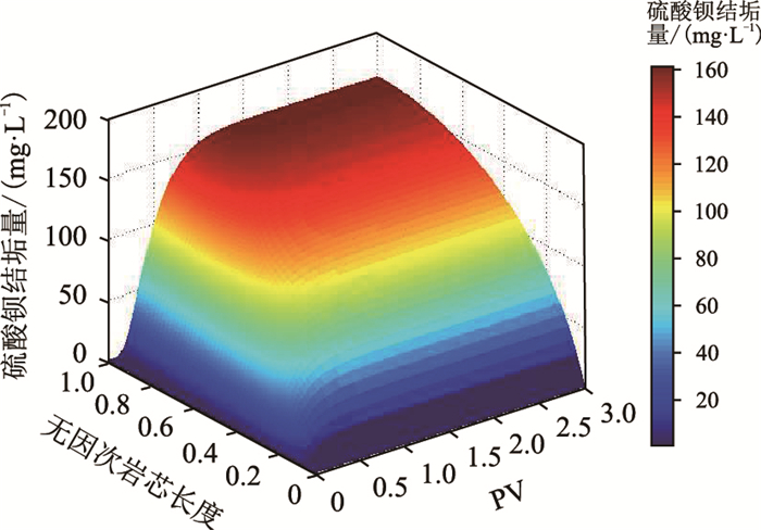
在得出模型的无因次反应速率常数和无因次扩散系数之后,对式(1) 在
 |
| 图7 不同驱替PV下岩芯1中硫酸钡沉淀分布 Fig. 7 Distribution of barium sulfate precipitation in the No. 1 core at different displacement PV |
 |
| 图8 不同驱替PV下岩芯2中硫酸钡沉淀分布 Fig. 8 Distribution of barium sulfate precipitation in the No. 2 core at different displacement PV |
由图 7和图 8可知,当含有SO
(1) 通过测定驱替实验中岩芯出口端Ba
(2) 对含扩散项的硫酸钡结垢动力学模型有限差分并采用第四阶和第五阶Runge-Kutta方程求解,可以避免求解解析解时岩芯入口端Ba
(3) 岩芯出口端的Ba
(4) 岩芯中的硫酸钡结垢量随模拟注入水注入量的增大而增大。
(5) 随着模拟注入水注入体积的增加,最大结垢量的位置逐步向岩芯中部转移。
(6) 在沿岩芯长度方向上,结垢量呈现出先增加后减小的趋势。
符号说明
ϕ—岩芯孔隙度,无因次;
| [1] | MOGHADASI J, MÜLLER-STEINHAGEN H, JAMIALAHMADI M, et al. Model study on the kinetics of oil field formation damage due to salt precipitation from injection[J]. Journal of Petroleum Science & Engineering, 2004, 43(3-4): 201–217. doi: 10.1016/j.petrol.2004.02.-014 |
| [2] | 李雪娇. 硫酸钡结垢影响因素及化学阻垢实验研究[D]. 成都: 西南石油大学, 2015. http://cdmd.cnki.com.cn/Article/CDMD-10615-1015599056.htm |
| [3] |
李洪建, 孟雪, 李然, 等. 影响硫酸钡阻垢效果因素实验研究[J].
西南石油大学学报(自然科学版), 2014, 36(1): 139–144.
LI Hongjian, MENG Xue, LI Ran, et al. Experimental study on factors affecting the effect of barium sulfate scale inhibition[J]. Journal of Southwest Petroleum University (Science & Technology Edition), 2014, 36(1): 139–144. doi: 10.11885/j.issn.1674-5086.2013.06.23.01 |
| [4] |
陈满. 基于化学动力学原理的硫酸钡结垢模型研究[D]. 成都: 西南石油大学, 2014.
CHEN Man. A study on barium sulfate scaling prediction model based on chemical kinetics[D]. Chengdu:Southwest Petroleum University, 2014. http://kns.cnki.net/KCMS/detail/detail.aspx?filename=xnsy201604019&dbname=CJFD&dbcode=CJFQ |
| [5] | 孙建波. 姬塬油田结垢对储层损害影响及解堵实验研究[D]. 成都: 西南石油大学, 2015. http://cdmd.cnki.com.cn/Article/CDMD-10615-1015599055.htm |
| [6] |
李洪建, 李振志, 陈宗林, 等. 高矿化度产出水集输中的阻垢实验研究[J].
西南石油大学学报(自然科学版), 2008, 30(5): 133–136.
LI Hongjian, LI Zhenzhi, CHEN Zonglin, et al. Scale prevention experiment research in gathering about highly mineralized production water[J]. Journal of Southwest Petroleum University (Science & Technology Edition), 2008, 30(5): 133–136. doi: 10.3863/j.issn.1000-2634.2008.05.-031 |
| [7] | RYZNAR J W, LANGELIER W F. A new index for determining amount of calcium carbonate scale formed by a water[J]. Journal(American Water Works Association), 1944, 36(4): 472–486. |
| [8] | ODDO J E, TOMSON M B. Why scale forms in the oil field and methods to predict it[J]. SPE Production and Facilities, 1994, 9(1): 47–54. doi: 10.2118/21710-PA |
| [9] | OD DO, J E, TOMSON, M B. Simplified calculation of CaCO3 saturation at high temperatures and pressures in brine solutions[J]. Journal of Petroleum Technology, 1982, 34(7): 1583–1590. doi: 10.2118/10352-PA |
| [10] | PITZER K S, PEIPER J C, BUSEY R H. Thermodynamic properties of aqueous sodium chloride solutions[J]. Journal of Physical and Chemical Reference Data, 1984, 13(1): 1–102. doi: 10.1063/1.555709 |
| [11] | WANG Peiming, ANDERKO A, YOUNG R D. A speciation-based model for mixed-solvent electrolyte systems[J]. Fluid Phase Equilibria, 2002, 203(1): 141–176. doi: 10.1016/S0378-3812(02)00178-4 |
| [12] | BEDRIKOVETSKY P G, LOPES Jr R P, ROSARIO F F, et al. Oilfield scaling-Part Ⅰ:Mathematical and laboratory modeling[C]. SPE 81127, 2003. doi:10.2118/81127-MS |
| [13] | BEDRIKOVETSKY P G, GLADSTONE P M, LOPES Jr R P, et al. Oilfield scaling-part Ⅱ:Productivity index theory[C]. SPE 81128, 2003. doi:10.2118/81128-MS |
| [14] | BEDRIKOVETSKI P, SILVA R, DAHER J, et al. Welldata-based prediction of productivity decline due to sulphate scaling[J]. Journal of Petroleum Science & Engineering, 2007, 68(1-2): 60–70. doi: 10.1016/j.petrol.-2009.06.006 |
| [15] | BEDRIKOVETSKY P G, MORAES G P, MONTEIRO R, et al. Characterization of sulphate scaling formation damage from laboratory measurements (to predict wellproductivity decline)[C]. SPE 93121, 2005. doi:10.2118/-93121-MS |
| [16] | BEDRIKOVETSKY P G, LOPES Jr R P, GLADSTONE P M, et al. Barium sulfate oilfield scaling:Mathematical and laboratory modeling[C]. SPE 87457, 2004. doi:10.-2118/87457-MS |
| [17] | MACKAY E. Predicting in situ sulphate scale deposition and the impact on produced ion concentrations[J]. Chemical Engineering Research and Design, 2003, 81(3): 326–332. doi: 10.1205/02638760360596874 |
| [18] | GRAHAM G M, COLLINS I R. Assessing scale risks and uncertainties for subsea marginal field developments[C]. SPE 87460, 2004. doi:10.2118/87460-MS |
| [19] | CIVAN F. Reservoir formation damage:Fundamentals, modeling, assessment, and mitigation[M]. Burlington MA: Gulf Professional Publishing, 2007. |
| [20] | BINMERDHAH A B, YASSIN A A M, MUHEREI M A. Laboratory and prediction of barium sulfate scaling at high-barium formation water[J]. Journal of Petroleum Science & Engineering, 2010, 70(1-2): 79–88. doi: 10.1016/-j.petrol.2009.10.001 |
 2017, Vol. 39


