2. 中国石化华北石油工程有限公司, 河南 郑州 450006;
3. 中国石化华北分公司工程技术研究院, 河南 郑州 450006
2. Petroleum Engineering Company of North China, SINOPEC, Zhengzhou, Henan 450006, China;
3. Engineering Technology Research Institute of North China, SINOPEC, Zhengzhou, Henan 450006, China
大牛地气田储集类型为中国典型的特低渗砂岩气层,其地质特征为“三低、两高、一多、一强”,即:低孔低压特低渗,高毛管力、高基岩应力,储层多(纵向发育8套储层),非均质性强(辫状河道沉积)。为了实现气化山东,年产天然气30×108 m3,稳定供气20年的目标,在大牛地气田试验了水平井钻井技术,并经历了以下几个阶段[1-6]:探索试验阶段(2002-2007年),φ215.9 mm的水平井眼,实现一类储层近平衡自然建产;推广应用阶段(2008-2009年),实现二、三类储层欠平衡建产;提速提效阶段(2010年至今),采用长水平段水平井(φ152.4 mm井眼)+分段压裂。
目前大牛地气田小井眼长水平井水平段长度普遍在1 000~1 500 m,在水平段的后期钻井过程中,随着水平段长度的增加,钻具摩阻大、钻头加压困难、钻速低、井眼轨迹调控困难,本文针对大牛地气田小井眼长水平段水平井的摩阻扭矩控制难题开展了相关方面的理论研究,并在此基础上提出了一套行之有效的摩阻扭矩控制技术。
1 摩阻扭矩计算模型 1.1 假设条件摩阻扭矩的预测是小井眼长水平段水平井能否顺利钻成的关键因素之一,考虑到前人在摩阻扭矩方面所做的相关研究以及大牛地气田小井眼水平井的实钻情况,本文对摩阻扭矩计算模型做如下假设[7-13]:
(1) 在钻具组合段采用连系梁的方法进行分析,且不发生屈曲;
(2) 钻具组合的上部钻杆采用软杆模型,且受压段钻杆为正弦屈曲;
(3) 考虑钻井液黏滞性对摩阻扭矩的影响,钻井液为宾汉塑性流体;
(4) 井眼曲率以实钻为准。
1.2 模型建立 1.2.1 钻具组合段摩阻扭矩图 1为轴向载荷和横向载荷共同作用下梁的变形示意图,横向集中载荷
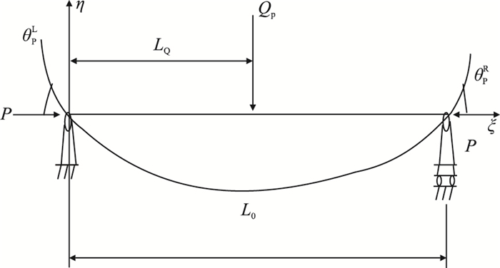 |
| 图1 轴向载荷与横向载荷作用下梁的变形示意图 Fig. 1 Deformation diagram of beam under the axial and lateral loads |
| $ \eta = \left\{ {\begin{array}{*{20}{l}} {\dfrac{{{Q_{\rm{P}}}\sin \left( {k{L_0} -k {L_{\rm{Q}}}} \right)}}{{P k \sin \left( {k {L_0}} \right)}}\sin \left( {k\xi } \right) -\dfrac{{{Q_{\rm{P}}}({L_0} -{L_{\rm{Q}}})\xi }}{{P {L_0}}}} & {\left( {0 \leqslant \xi < {L_{\rm{Q}}}} \right)}\\[10pt] {\dfrac{{{Q_{\rm{P}}}\sin \left( {k {L_{\rm{Q}}}} \right)}}{{P k \sin \left( {k {L_0}} \right)}}\sin \left[{k({L_0}-\xi )} \right] -\dfrac{{{Q_{\rm{P}}} {L_{\rm{Q}}}({L_0} -\xi )}}{{P {L_0}}}} & {\left( {{L_{\rm{Q}}} \leqslant \xi < {L_0}} \right)} \end{array}} \right. $ | (1) |
式中:
k-管材物理参数,
E-梁的弹性模量,Pa;
I-梁的惯性矩,m4;
P-轴向载荷,N。
对式(1)求导,并令
| $ \left\{ \begin{array}{l} \theta_{\rm{P}}^{\rm{L}} = {\eta ^{'}}\left| {_{\xi = 0}} \right. = \dfrac{{{Q_{\rm{P}}}\sin \left( {k \cdot {L_0} -k \cdot {L_{\rm{Q}}}} \right)}}{{P\sin \left( {k \cdot {L_0}} \right)}} -\dfrac{{{Q_{\rm{P}}}\left( {{L_0} -{L_{\rm{Q}}}} \right)}}{{P \cdot {L_0}}}\\[10pt] \theta_{\rm{P}}^{\rm{R}} = {\eta^{'}}\left| {_{\xi = {L_0}}} \right. = -\dfrac{{{Q_{\rm{P}}}\sin \left( {k \cdot {L_{\rm{Q}}}} \right)}}{{P\sin \left( {k \cdot {L_0}} \right)}} + \dfrac{{{Q_{\rm{P}}} \cdot {L_{\rm{Q}}}}}{{P \cdot {L_0}}} \end{array} \right. $ | (2) |
以上两式结合管柱的三弯矩方程和相应的边界条件得到约束点的支撑力
| $ \left\{ \begin{array}{l} N_{i, {\rm{P}}} = \dfrac{{M_{i -1, {\rm{P}}} -M_{i, {\rm{P}}} }}{{\Delta L_i }} + \dfrac{{q_{i, {\rm{P}}} \Delta L_i }}{2} + \dfrac{{M_{i + 1, {\rm{P}}} -M_{i, {\rm{P}}} }}{{\Delta L_{i + 1} }} + \dfrac{{q_{i + 1, {\rm{P}}} \Delta L_{i + 1} }}{2} \\[10pt] N_{i, {\rm{Q}}} = \dfrac{{M_{i -1, {\rm{Q}}} -M_{i, {\rm{Q}}} }}{{\Delta L_i }} + \dfrac{{M_{i + 1, {\rm{Q}}} -M_{i, {\rm{Q}}} }}{{\Delta L_{i + 1} }} \\ \end{array} \right.\left( {i = 1, 2, \cdots, n -1} \right) $ | (3) |
式中:
从而得到约束点的正压力
| $ N = \sqrt {{N_{i, {\rm{P}}}}^2 + {N_{i, {\rm{Q}}}}^2} $ | (4) |
式中:
N-微元段正压力,N。
最后叠代求解得到整个钻具组合段的摩阻扭矩。
1.2.2 钻杆段摩阻扭矩图 2为钻杆微元段受力示意图,根据静力学平衡方程得到微元段载荷为
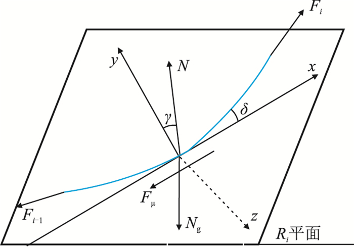 |
| 图2 微元段受力示意图 Fig. 2 Force analysis of infinitesimal section |
| $ \left\{ {\begin{array}{*{20}{l}} {{F_i}\cos \delta = {F_{i - 1}}\cos \delta + {N_{\rm{g}}}\cos \alpha + {F_{\mu }}}\\ {{F_i}\sin \delta + {F_{i - 1}}\sin \delta - {N_{\rm{g}}}\sin \theta \sin \beta + \sqrt {{N^2} - N_{\rm{g}}^2\cos {^2}\theta } = 0}\\ {{F_\mu } = \pm \mu N}\\ {{N_{\rm{g}}} = {W_{\rm{e}}}\Delta L\left( {1 - {\rho _{\rm{m}}}/7.85} \right)} \end{array}} \right. $ | (5) |
式中:
扭矩载荷
| $ {T_i} = {T_{i -1}} + {\mu _{\rm{t}}}{r_{\rm{w}}}N $ | (6) |
式中:
| $ {F_{\rm{a}}} = 0.5{\beta ^2}{N_{\rm{g}}}\sin \alpha $ | (7) |
式中:
| $ \tau \left( r \right) = \tau _0 + \mu _0 \left[{\dfrac{1}{{2\mu _{\rm{v}} }}\dfrac{{{\rm{d}}p}}{{{\rm{d}}x}}(R_{{\rm{bit}}}-r) + \dfrac{{v_{\rm{p}} }}{{R_{{\rm{bit}}}-r}}} \right] $ | (8) |
(2) 起下钻时管内附加应力
| $ \tau \left( r \right) = \tau _0 + \mu _0 \dfrac{1}{{2\mu _{\rm{v}} }}\dfrac{{{\rm{d}}p}}{{{\rm{d}}x}}r $ | (9) |
(3) 钻柱旋转时环空附加应力
| $ \tau \left( r \right) = \tau _0 + \mu _0 \Omega \dfrac{{R_{{\rm{bit}}}^2 + r}}{{R_{{\rm{bit}}}^2 -r}} $ | (10) |
(4) 钻柱旋转时管内附加应力
| $ \tau \left( r \right) = \tau _0 + \mu _0 \Omega $ | (11) |
式中:
r-距钻具中心的距离,m;
dp/dx-流动压降梯度,Pa/m;
摩擦系数获取的方法主要有两种方法:第一种,也是最直接的方法便是通过室内实验进行测定;第二种,利用现场的实钻数据,然后利用模型进行反算获取。本文采用第二种方法来获取摩擦系数,以DP29H、DP39S、DP41S、DP30H、DP26T和DPS3井水平段钻进过程中实测的扭矩和大钩载荷,利用摩阻扭矩模型对管内和裸眼段的摩擦系数进行了反算,反算过程中所需的其他参数以实钻参数为准。大牛地气田水平井段实际扭矩及钩载如表 1所示。
| 表1 大牛地气田水平井段实际扭矩及钩载 Table 1 Actual torque and hook load of the Daniudi Gas Field |
从表中的分析结果可知:管内的平均摩擦系数为0.220,裸眼段的平均摩擦系数为0.325。
3 影响因素敏感性分析 3.1 水平段长度对摩阻扭矩的影响图 3和图 4分别给出了以DPS3井和DP34H井为例计算得到的扭矩与水平段长度的关系。在计算过程中超出实钻的水平段长度按直线延伸,无狗腿,且所有的钻具组合及其他计算所需参数均不变(如:钻压、转速、BHA、管内和裸眼段摩擦系数等)。
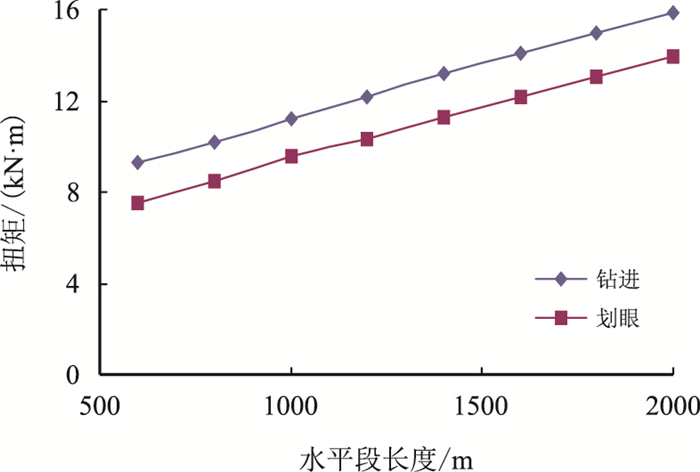 |
| 图3 水平段长度与扭矩的变化关系(DPS3井) Fig. 3 Relationship between horizontal length and torque (Well DPS3) |
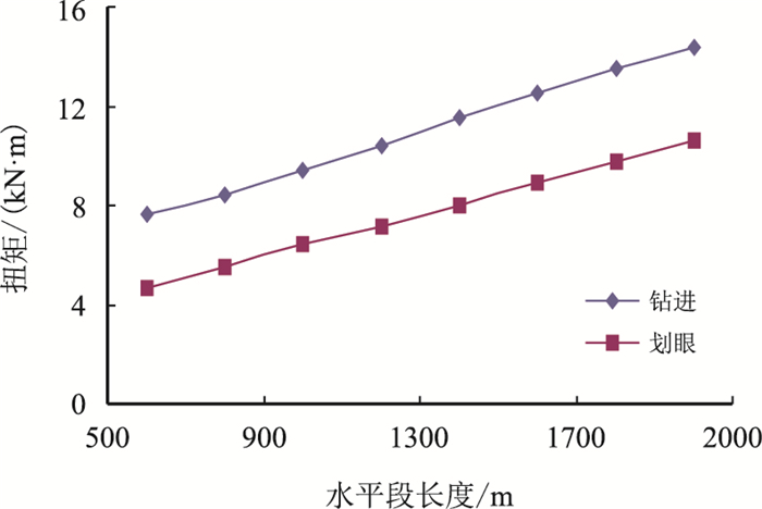 |
| 图4 水平段长度与扭矩的变化关系(DP34H井) Fig. 4 Relationship between horizontal length and torque (Well DP34H) |
从图 3和图 4可以看出:随着水平段长度的增加,钻进和起钻的扭矩均在增加,当水平段长度增加到2 000 m时,转盘处钻杆的扭矩值几乎接近G105钻杆所能承受的扭矩的极限值(16 kN·m),建议:在进行长水平段水平井中选用高钢级的钻杆,如S135钻杆。
图 5和图 6分别给出了DPS3井、DP34H井大钩载荷随水平段长度的变化关系,从图中可以看出:随着水平段长度的增加,大钩载荷降低,表明:随着水平段长度的增加,钻具在水平段受到的摩阻越来越大,当钻具摩阻达到一定值以后(即:水平段长度达到一定值),便很难施加钻压,此时的长度便是水平段的极限延伸长度。
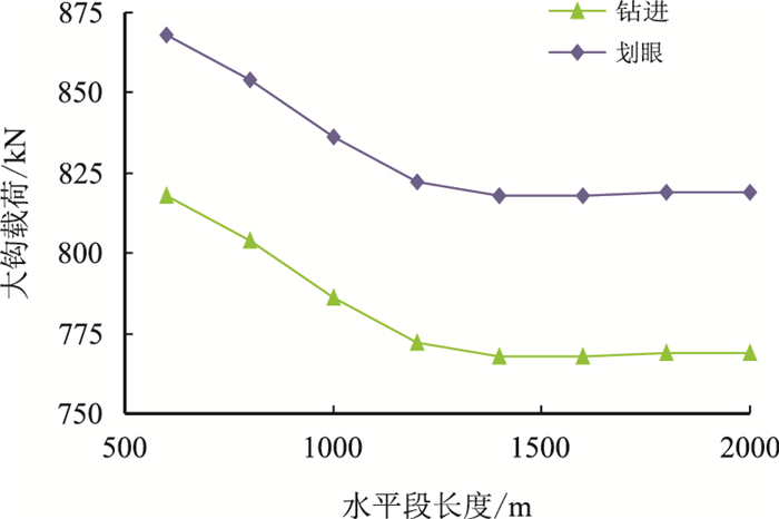 |
| 图5 水平段长度与钩载的变化关系(DPS3井) Fig. 5 Relationship between horizontal length and hook load (Well DPS3) |
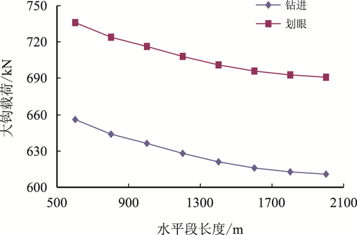 |
| 图6 水平段长度与大钩载荷的变化关系(DP34H井) Fig. 6 Relationship between horizontal length and hook load (Well DP34H) |
以DPH66井为例分析了单增剖面不同靶前位移与扭矩的关系,DPH66井水平段长度1 200 m,设计靶前位移350 m,单增剖面靶前位移与扭矩和钩载计算结果分别如图 7和图 8所示。
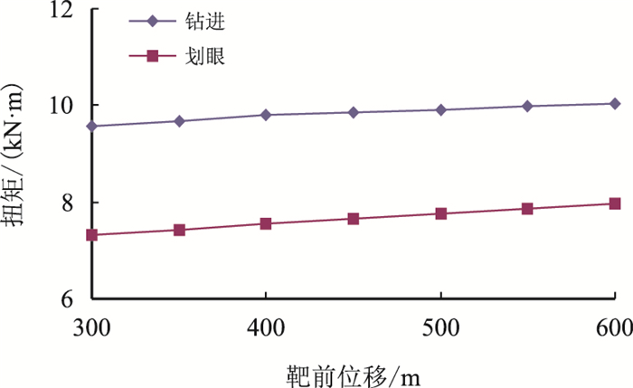 |
| 图7 单增剖面靶前位移与扭矩关系(DPH66井) Fig. 7 Relationship between torque and displacement of single gain profile (Well DPH66) |
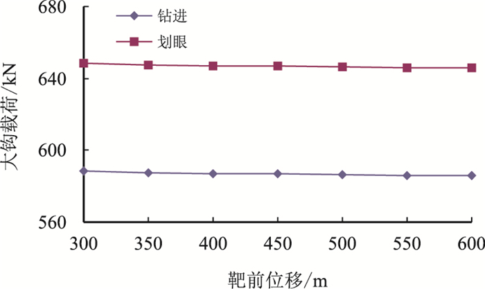 |
| 图8 单增剖面靶前位移与大钩载荷关系(DPH66井) Fig. 8 Relationship between hook load and displacement of single gain profile (Well DPH66) |
由图 7和图 8可知:随着靶前位移的增加,扭矩增加,但增加幅度较小;随着靶前位移的增加,钩载减小,但减小幅度较小。扭矩和钩载随靶前位移变化程度较小原因为:设计的造斜段轨迹为规则的圆弧轨迹,设计水平段轨迹狗腿度为零,从而导致扭矩和钩载随靶前位移的变化幅度较小。
3.3 钻具组合对摩阻扭矩的影响在φ152.4 mm的小井眼水平井中,可用的钻杆尺寸有φ88.9,φ101.6,φ114.3 mm,下面分析在使用不同尺寸钻杆情况时的摩阻扭矩。以DP26T井为例,在其他条件不变的情况下,分别计算使用φ88.9,φ101.6,φ114.3 mm钻杆时的扭矩,计算结果见图 9。
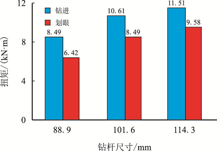 |
| 图9 不同尺寸钻杆对扭矩的影响(DP26T井) Fig. 9 The influence of different size of drill pipe on the torque (Well DP26T) |
从图 9中可以看出:在其他条件一定时,使用的钻杆尺寸越大扭矩也就越大;使用φ101.6 mm和φ114.3 mm钻杆的扭矩基本相当,但其与使用φ88.9 mm钻杆的扭矩相差较大。
图 10中给出了使用组合钻杆时的扭矩,从图中可以看出:组合钻杆较常规φ88.9 mm钻杆相比,扭矩变化不大。对比分析图 9和图 10可知:使用组合钻杆与使用单一尺寸钻杆相比,使用组合钻杆更能有效地控制扭矩。
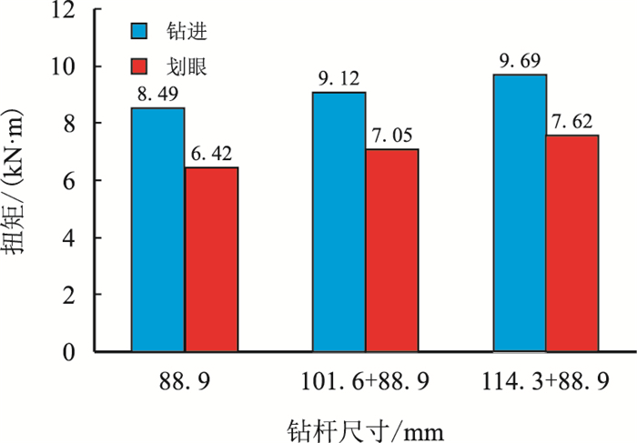 |
| 图10 组合钻杆对扭矩的影响(DP26T井) Fig. 10 The influence of assembly drill pipe on the torque (Well DP26T) |
以DP29H井为例来分析钻井液流变性对摩阻扭矩的影响规律。图 11和图 12分别给出了以DP29H}井实例分析的钻井液的屈服值和塑性黏度对扭矩的影响结果。
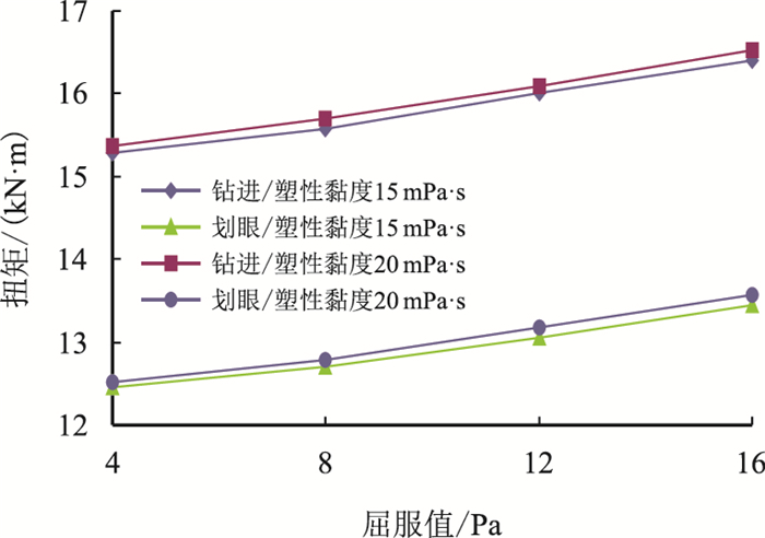 |
| 图11 钻井液的屈服值对扭矩的影响(DP29H井) Fig. 11 The influence of yield point on the torque (Well DP29H) |
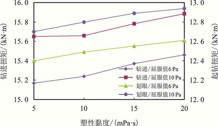 |
| 图12 钻井液的塑性黏度对扭矩的影响(DP29H井) Fig. 12 The influence of plastic viscosity on the torque (Well DP29H) |
由图 11可知:当其他参数一定的情况下,随着钻井液屈服值的增加,扭矩增加;当屈服值一定时塑性黏度越小扭矩越小。
由图 12可知:当其他参数一定的情况下,随着钻井液塑性黏度的增加,扭矩增加;当塑性黏度一定时屈服值越小扭矩越小。表明:钻井液流变性越好,对井内钻具运动影响越小,越有利于井内摩阻扭矩的控制。
4 现场应用DPH7井是盒1气层的一口小井眼水平井,完钻井深4 145 m,水平段长1 400 m,水平位移1 800 m,水平段钻具组合为:φ152.4 mm钻头+φ148 mm扶正器+1.25°螺杆+φ120 mm 无磁钻铤+φ102 mm}钻杆+φ102 mmHWDP*39+φ88.9 mm钻杆,钻井液体系为钾铵基聚合物,密度:1.04 g/cm3,塑性黏度16 mPa·s,屈服值6 Pa,钻压80 kN,转速40 r/min,排量17 L/s。图 13给出了DPH7井实测扭矩与模型计算扭矩值,从图中可知:计算值与实测值吻合较好。图 14给出了DPH7井实钻轨迹与设计轨迹,该井完钻后水平段平均全角变化率1.79°/(30 m),水平段轨迹控制较好。
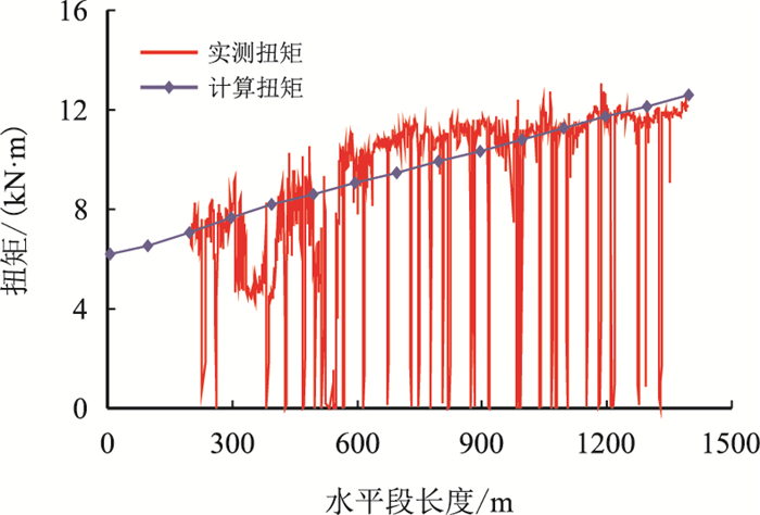 |
| 图13 DPH7井实测扭矩与计算扭矩 Fig. 13 Actual torque and calculated torque of the Well DPH7 |
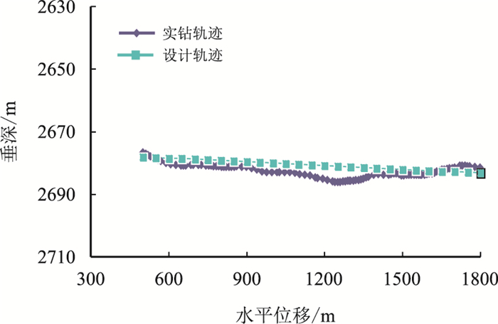 |
| 图14 DHP17井实钻与设计轨迹 Fig. 14 Actual trajectory and designed trajectory of the Well DPH7 |
(1) 针对大牛地气田小井眼水平井实际情况建立了摩阻扭矩计算的分段模型,模型计算结果与实测结果吻合较好,具有较高的精度。
(2) 通过模型反算得到了大牛地气田小井眼水平井套管内的平均摩擦系数为0.220,裸眼段的平均摩擦系数为0.325。
(3) 通过摩阻扭矩的影响因素敏感性分析可知:随着水平段长度的增加,扭矩在增加,大钩载荷降低;随着靶前位移的增加,扭矩增加,大钩载荷减小,但变化幅度均较小;使用复合钻杆既能满足钻井相关需求,又能有效控制摩阻扭矩;钻井液的流变性能越好,对摩阻扭矩的影响越小。
| [1] |
常兴浩, 田景春, 李良, 等. 大牛地气田下石盒子组岩相测井相与砂体储集关系及其平面分布的油气意义[J].
成都理工大学学报:自然科学版, 2013, 40 (4) : 417 –423.
Chang Xinghao, Tian Jingchun, Li Liang, et al. Relationships between lithofacies-logging facies and sandbody reservoir properties and the petroleum geological significance of lithofacies-logging facies horizontal distribution of Xiashihezi Formation in Daniudi Gas Field[J]. Journal of Chengdu University of Technology:Science & Technology Edition, 2013, 40 (4) : 417 –423. |
| [2] |
韩海英, 王志章, 李汉林. 地震多属性分析在大牛地气田储集层预测中的应用[J].
新疆石油地质, 2013, 34 (3) : 331 –334.
Han Haiying, Wang Zhizhang, Li Hanlin. Application of seismic multi attribute analysis to reservoir prediction in Daniudi Gas Field[J]. Xinjiang Petroleum Geology, 2013, 34 (3) : 331 –334. |
| [3] |
朱春俊, 王延斌. 大牛地气田低渗储层成因及评价[J].
西南石油大学学报:自然科学版, 2011, 33 (1) : 49 –56.
Zhu Chunjun, Wang Yanbin. Reservior genesis and evaluation for the low porosity and permeability sandstone in the Daniudi Gasfield[J]. Journal of Southwest Petroleum University:Science & Technology Edition, 2011, 33 (1) : 49 –56. |
| [4] |
陈作, 何青, 王宝峰, 等. 大牛地气田长水平段水平井分段压裂优化设计技术[J].
石油钻探技术, 2013, 41 (6) : 82 –85.
Chen Zuo, He Qing, Wang Baofeng, et al. Design optimization of staged fractureing for long lateral horizontal wells in Daniudi Gas Field[J]. Petroleum Drilling Techniques, 2013, 41 (6) : 82 –85. |
| [5] |
汤明, 何世明, 邢景宝, 等. 大牛地气田DP14水平井氮气泡沫钻井实践与认识[J].
天然气工业, 2010, 30 (3) : 74 –76.
Tang Ming, He Shiming, Xing Jingbao, et al. Practices and knowledge from nitrogen foam drilling at the well DP-14 in the Daniudi Gas Field[J]. Natural Gas Industry, 2010, 30 (3) : 74 –76. |
| [6] |
郝蜀民, 惠宽洋, 李良. 鄂尔多斯盆地大牛地大型低渗气田成藏特征及其勘探开发技术[J].
石油与天然气地质, 2006, 27 (6) : 762 –768.
Hao Shumin, Hui Kuanyang, Li Liang. Reservoiring features of Daniudi low-permeability Gas Field in Ordos Basin and its exploration and development technologies[J]. Oil & Gas Geology, 2006, 27 (6) : 762 –768. |
| [7] | Johansick C A, Friesen D B, Dawson R. Torque and drag in directional wells prediction and measurement[C]. SPE 11380, 1984. |
| [8] | Sheppard M C, Wick C, Burgess T. Designing well paths to reduce drag and torque[C]. SPE 15463, 1987. |
| [9] | Whitten R G. Application of side-force analysis and mwd to reduce drilling costs[C]. SPE 16113, 1987. |
| [10] | Ho H-S. An improved modeling program for calculating the torque and drag in directional and deep wells[C]. SPE 18047, 1988. |
| [11] | Sheppard M C, Wick C, Burgess T, et al. Designing well paths to reduce drag and torque[C]. SPE 15463, 1987. |
| [12] |
马善洲, 韩志勇. 水平井钻柱摩阻力和摩阻力矩的计算[J].
石油大学学报:自然科学版, 1996, 20 (6) : 24 –28.
Ma Shanzhou, Han Zhiyong. Computation of torque and drag of drill string in horizontal well[J]. Journal of the University of Petroleum China, 1996, 20 (6) : 24 –28. |
| [13] |
闫铁, 李庆明, 王岩, 等. 水平井钻柱摩阻扭矩分段计算模型[J].
大庆石油学院学报, 2011, 35 (5) : 69 –72, 83.
Yan Tie, Li Qingming, Wang Yan, et al. Segmental calculation model for torque and drag of drillstring in horizontal wells[J]. Journal of Daqing Petroleum Institute, 2011, 35 (5) : 69 –72, 83. |
| [14] | Rapier D. Drill pipe buckling in inclined holes[C]. SPE 11167, 1984. |
| [15] | Newman K R,Corrigan M,Cheatham J B. Safely exceeding the critical buckling load in highly deviated holes[C]. SPE 19229, 1989. |
| [16] | Paslay P R, Bogy D B. The stability of a circular rod laterally constrained to be in contact with an inclined circular cylinder[J]. Journal of Applied Mechanics, 1964, 31 (4) : 605 –610. DOI:10.1115/1.3629721 |
| [17] |
高国华, 李琪, 李淑芳. 管柱在水平井眼中的屈曲分析[J].
石油学报, 1996, 17 (3) : 123 –130.
Gao Guohua, Li Qi, Li Shufang. A buckling analysis of pipe string in horizontal boreholes[J]. Acta Petrolei Sinica, 1996, 17 (3) : 123 –130. |
| [18] |
高国华, 张福祥, 王宇, 等. 水平井眼中管柱的屈曲和分叉[J].
石油学报, 2001, 22 (1) : 95 –99.
Gao Guohua, Zhang Fuxiang, Wang Yu, et al. Buck-ling and bifurcation of pipes in horizontal wells[J]. Acta Petrolei Sinica, 2001, 22 (1) : 95 –99. |
| [19] | 张捷千, 章光华, 陈允文. 真实流体力学(I)[M]. 北京: 清华大学出版社, 1986 : 118 -125. |
| [20] |
孙玉学, 李启明, 孔翠龙, 等. 基于卡森流体的水平井波动压力预测新方法[J].
钻井液与完井液, 2011, 28 (2) : 29 –31.
Sun Yuxue, Li Qiming, Kong Cuilong, et al. New prediction method on surge pressure in horizontal well basing on casson fluid[J]. Drilling Fluid & Completion Fluid, 2011, 28 (2) : 29 –31. |
| [21] | Polaszek S C, Fraser L J. Drilling fluid formulation for shallow offshore horizontal well applications[C]. SPE 22577, 1991. |
| [22] | 郑永刚. 非牛顿流体流动理论及其在石油工程中的应用[M]. 北京: 石油工业出版社, 1995 : 39 -41. |
 2015, Vol. 37


